-
Thread
Eeprom Philip Pines Auslesen mit CH341
EEPROM auf diese Weise problemlos auslesen? Da der Hersteller des EEPROMs im CH341A‑Programm bzw. in AsProgrammer nicht gelistet ist, würde ich es mit folgenden Chip‑Typen versuchen: 25040 25AA040 25A040 25LC040 usw. Falls ihr bessere oder elegantere Lösungen habt, freue ich mich über
mehr. Kannst du auch ein Programm zum Auslesen empfehlen? Ich benutze das Programm CH341 AS Liebe Grüße Kalle
-
Thread
Frage zur Schaltzeit vom 74HC138N
of the setting of Data Direction bit DDxn, the port pin can be read through the PINxn register bit. As shown in Ports as General Digital I/O, the PINxn register bit and the preceding latch constitute a synchronizer. This is needed to avoid metastability if the physical pin changes value near the edge
-
Thread
Blackout in Spanien: Abschlussbericht
dort Merit-Order Pricing? Das ist kein Naturgesetz, z.B. bei Ausschreibungsverfahren benutzt man Pay-As-Bid. Warum müssen Erneuerbare zum Minimalpreis als Graustrom vermarktet werden? Warum haben wir so komplizierte energierechtliche Regelungen, dass das Aufstellen von Speichern in stark belasteten
Merit-Order Pricing? Das ist > kein Naturgesetz, z.B. bei Ausschreibungsverfahren benutzt man > Pay-As-Bid. Warum müssen Erneuerbare zum Minimalpreis als Graustrom > vermarktet werden? OK. Alle sind dumm. Aber ich hätte gerne die vorgeschlagene Alternative mit ~350 Knoten mit unterschiedlichen Preisen
-
 Bild
Bild
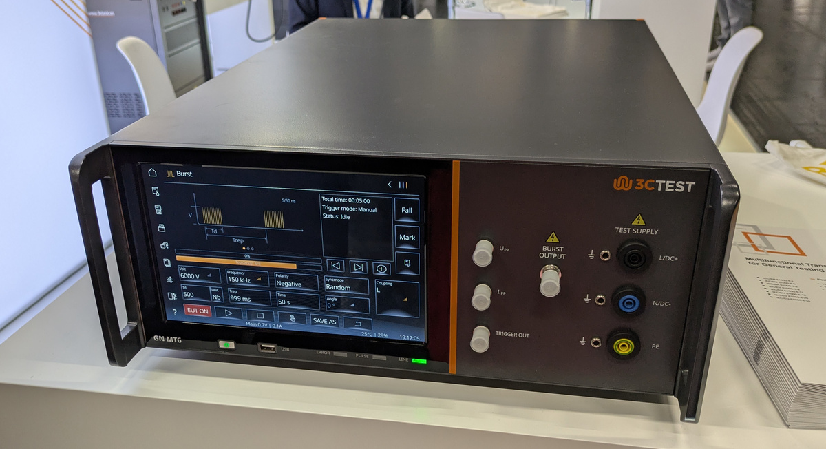
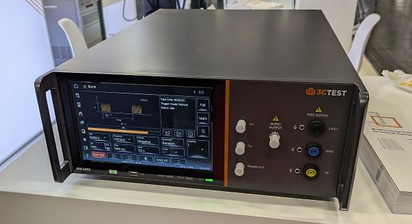
3CTEST GN MT6 Burst Test Supply Messgerät
ms Trigger mode: Manual Status: Idle Fail Mark 6000 V 150 kHz Negative Random Coupling EUT ON SAVE AS 25°C | 29% 19:17:05 3CTEST TEST SUPPLY U_PP BURST OUTPUT L/DC+ I_PP N/DC- TRIGGER OUT PE GN MT6 USB ERROR PULSE LINE
-
Thread
Heute, Mi 25.3., möglicher 2. Start von Isar Aerospace ab 21 Uhr
Da die Ursache in der Kürze der Zeit nicht behoben werden konnte, wurde der Start abgebrochen. "As a result of the delay, the vehicle encountered an increase in engine fuel temperature, which could not be addressed within the shortened countdown and hence forced the abort of the mission." Dritter
-
 Bild
Bild
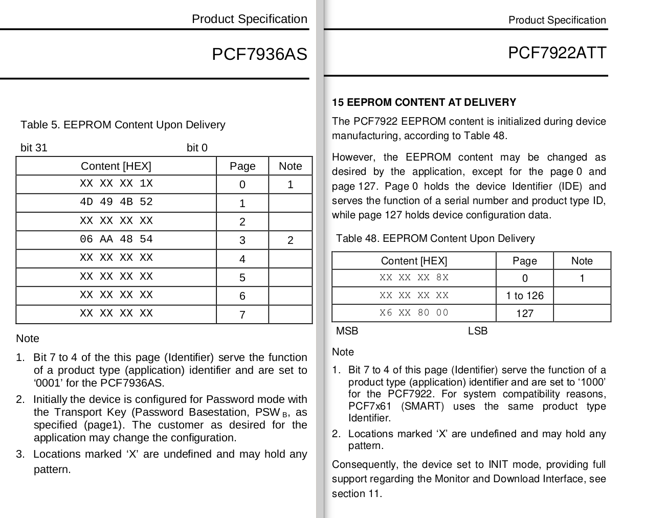
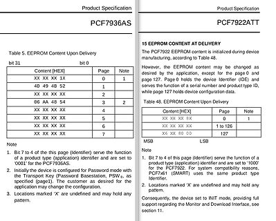
Ausschnitt aus einem Datenblatt für PCF7936AS und PCF7922ATT
Product Specification PCF7936AS PCF7922ATT Table 5. EEPROM Content Upon Delivery bit 31 bit 0 Content [HEX] Page Note XX XX XX 1X 0 1 4D 49 4B 52 1 XX XX XX 2 06 AA 48 54 3 2 XX XX XX 4 XX XX XX 5 XX XX XX 6 XX XX XX 7 Table 48. EEPROM
-
 Bild
Bild
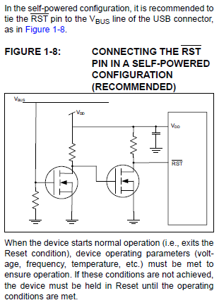
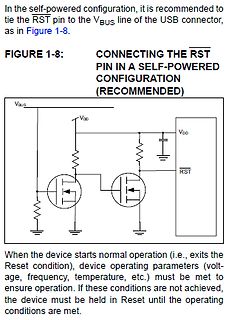
Schaltplan einer RST-Pin-Verbindung in Self-Powered-Konfiguration
self-powered configuration, it is recommended to tie the RST pin to the VBUS line of the USB connector, as in Figure 1-8. FIGURE 1-8: CONNECTING THE RST PIN IN A SELF-POWERED CONFIGURATION (RECOMMENDED) VBUS VDD RST
-
 Bild
Bild
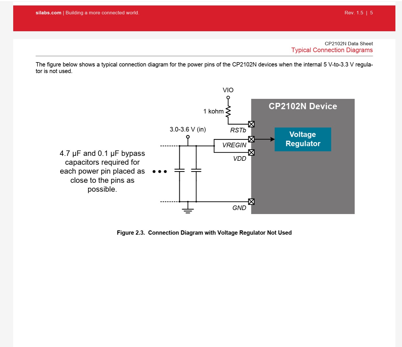
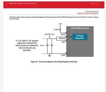
Verbindungsschema für CP2102N ohne internen Spannungsregler
VREGIN Voltage Regulator VDD 4.7 µF and 0.1 µF bypass capacitors required for each power pin placed as close to the pins as possible. GND Figure 2.3. Connection Diagram with Voltage Regulator Not Used
-
Thread
EMV-Probleme mit LC-Display
Entladung einer Kapazität mit 1pF bei 20kV in etwa 10ns." Wobei 1pF schon SEHR wenig ist! Alleinf as HF-Kabel der Zuleitung hat da DEUTLICH mehr. Koax im Bereich 100pF/m, macht 1pF/cm.
-
 Bild
Bild
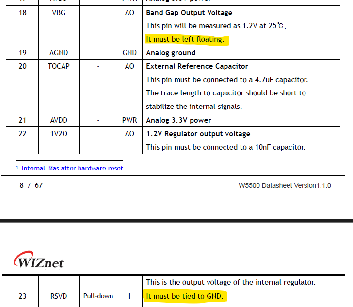
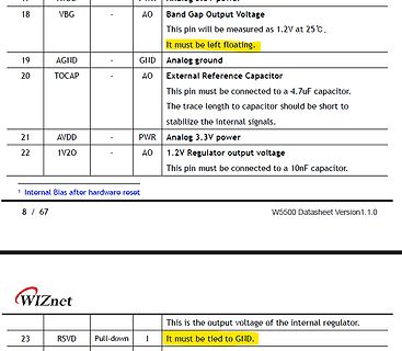
Ausschnitt einer Pinbelegungs-Tabelle aus einem Datenblatt
18 VBG - AO Band Gap Output Voltage This pin will be measured as 1.2V at 25°C. It must be left floating. 19 AGND - GND Analog ground 20 TOCAP - AO External Reference Capacitor This pin must be connected to a 4.7uF capacitor. The trace length to capacitor should be
-
Thread
verhalten von defines in C
Phase 7 ausgegeben: The resulting tokens are syntactically and semantically analyzed and translated as a translation unit.
-
 Bild
Bild
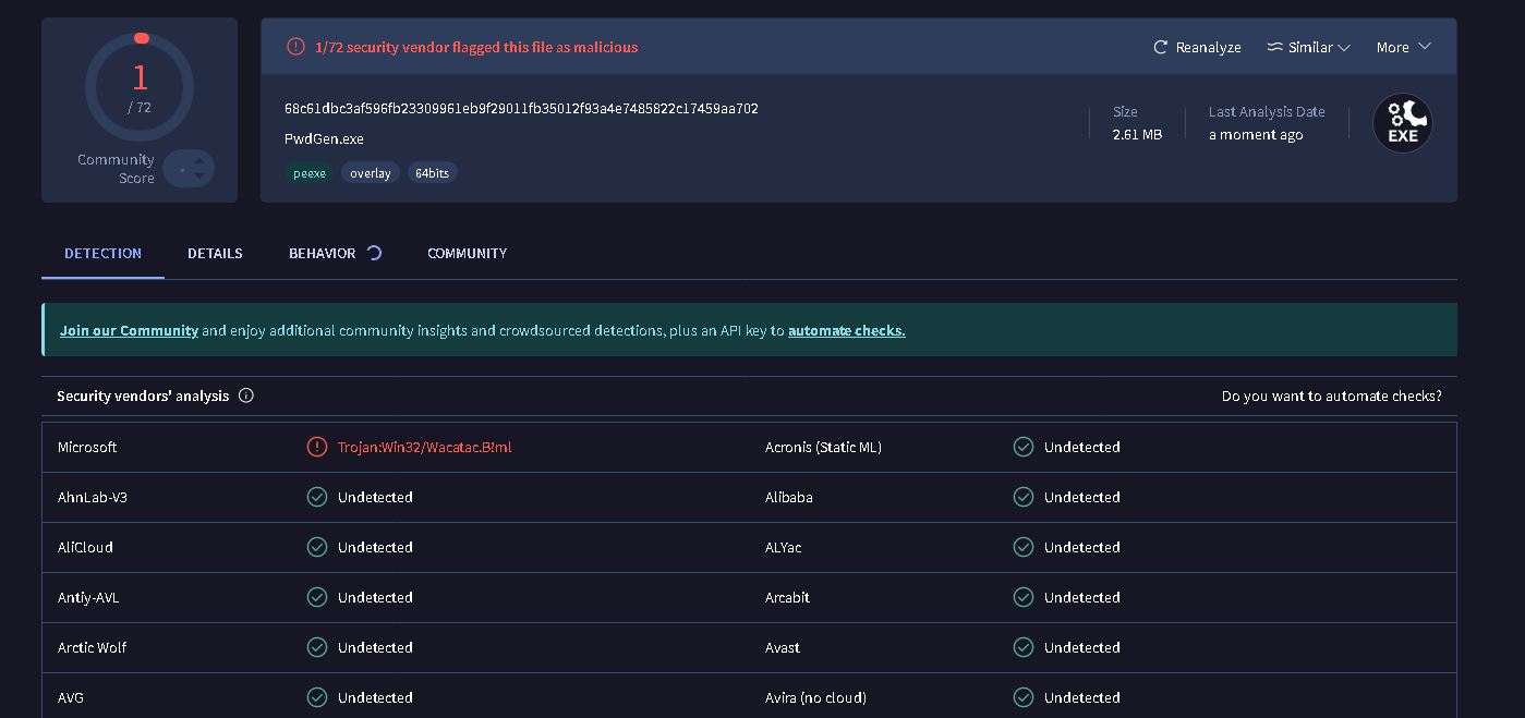
Screenshot einer VirusTotal-Analyse einer Datei
1/72 security vendor flagged this file as malicious 68c61dbc3af596fb23309961eb9f29011fb35012f93a4e7485822c17459aa702 PwdGen.exe Size 2.61 MB Last Analysis Date a moment ago Microsoft Trojan:Win32/Wacatac.B!ml AhnLab-V3 Undetected AliCloud Undetected

-
Thread
Amper 2026 – 27000 haben ihren Skill erhöht
market leaders. The format of the interactive program center AMPER STAGE in the pavilion and news such as the conference DronyX or Smart Industry has proven itself. In three days, more than 27 000 visitors, especially technicians from the presented sectors, but also from the related and customer disciplines
-
 Bild
Bild
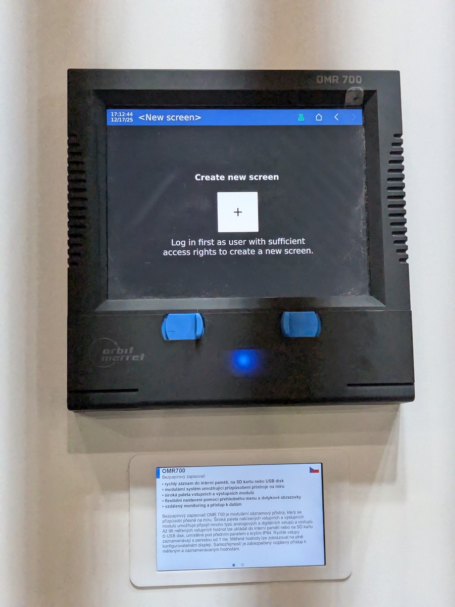
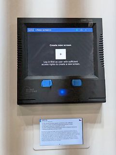
OMR 700 Display mit Fehlermeldung
OMR 700 17:12:44 <New screen> 12/17/25 Create new screen + Log in first as user with sufficient access rights to create a new screen. orbit merrel OMR700 Bezápisový zapisovač • rychlý záznam na SD kartu nebo USB disk • modulární systém umožňující přizpůsobení přístroje na míru
-
Thread
KiCad 10 erschienen, Raspberry Pi Connect mit Softwareupdates uvam
or more scripts to execute, along with data files that these scripts can use. These scripts are run as root so that they can access all of the file systems. I’ve already referred to running apt upgrade, but for custom software updates, you could create an artefact containing a .zip file and a script to
possible merger of their power semiconductor operations, it was learned Thursday. The move comes as automotive parts maker Denso Corp. is seeking to acquire Rohm, whose special committee is believed to be currently examining the acquisition offer. Rohm is expected to consider which offer would increase
-
 Bild
Bild
Werbebanner für das 15th Power Analysis & Design Symposium
Troubleshooting of Electronic Power Systems The 15th Power Analysis & Design Symposium will take place as a live, virtual event on Wednesday, April 29th, 2026. Experience a great day packed with live lectures from international electronics experts focusing on power supply design. Register now!

-
 Bild
Bild
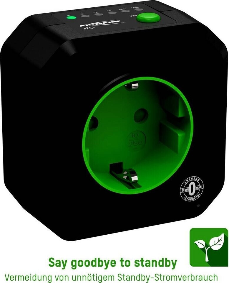
Steckdose mit Standby-Unterbrecher
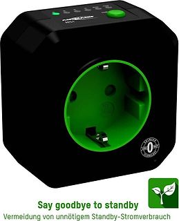
AKSMANN AESTI START 10 250 ZERO WATT TECHNOLOGY Say goodbye to standby Vermeidung von unnötigem Standby-Stromverbrauch
-
Thread
Stratosphärenballon
die notwendigen und eingebrachten Genehmigungen rechtlich unschuldig wäre. AATiS hat ja mit ihrem AS825 Phönix ein Miniballonprojekt in ihrem Portfolio: https://aatis.de/content/bausatz/AS825_Phoenix-Der_Stratosph%C3%A4renfl%C3%BCsterer Vom Gewicht her dürfte dieses eigentlich keinerlei Gefahr für
sie ihre Position verändert hat, also lag sie laut GPS-Daten von der Sonde auf einem Acker an der AS Giengen-Herbrechtingen der BAB7, der ist ca 700 m über MSL. Du kannst ja mal nach RS41Tracker googeln, das ist die Software. Die hat ein Italiener entwickelt, daher nicht wundern, dass die Homepage
-
Thread
KiCad 10.0 ist Erschienen.
Charras added another long-requested feature: the ability to show wire crossings that aren’t connected as "hop-over" arcs rather than straight lines.
-
Thread
Erfahrungen mit AI-Coding
(1 << LED_PIN); /* ── Timer2 asynchron konfigurieren ──────────────── */ ASSR |= (1 << AS2); /* externen 32768-Hz-Quarz nutzen */ TCCR2A = (1 << WGM21); /* CTC-Modus (Top = OCR2A) */ TCCR2B = (1 << CS20); /* Prescaler /1 */ OCR2A = TICK_TOP
TIMSK2 = 0; /* Enable asynchronous Timer2 clock from 32.768 kHz crystal */ ASSR |= (1 << AS2); /* CTC mode, OCR2A as top */ TCCR2A = (1 << WGM21); /* * 32.768 kHz / 128 = 256 Hz * 1 compare tick = 3.90625 ms when OCR2A = 0 * * For an easy 10 ms-ish
-
 Bild
Bild
Textauszug über einen Command Decoder
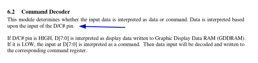
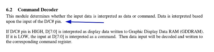
6.2 Command Decoder This module determines whether the input data is interpreted as data or command. Data is interpreted based upon the input of the D/C# pin. If D/C# pin is HIGH, D[7:0] is interpreted as display data written to Graphic Display Data RAM (GDDRAM). If it is LOW, the input at D[7:0] is interpreted as a command. Then data input will be decoded and written to the corresponding command register.
-
 Bild
Bild
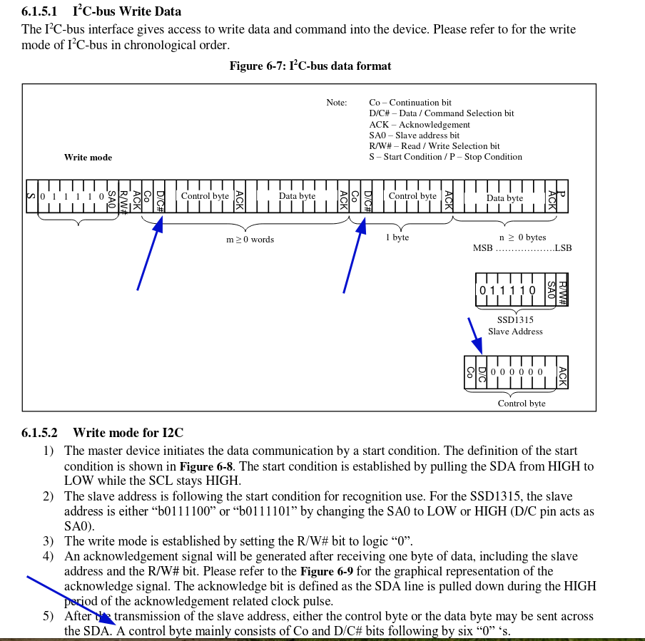
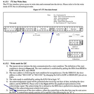
Diagramm des I2C-Bus Schreibmodus Datenformats
the slave address is either "0111100" or "0111101" by changing the SA0 to LOW or HIGH (D/C pin acts as SA0). 3) The write mode is established by setting the R/W# bit to logic "0". 4) An acknowledgement signal will be generated after receiving one byte of data, including the slave address and the R/W#
-
 Bild
Bild
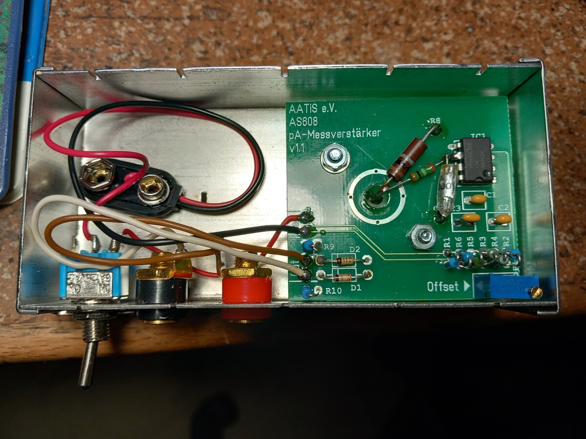
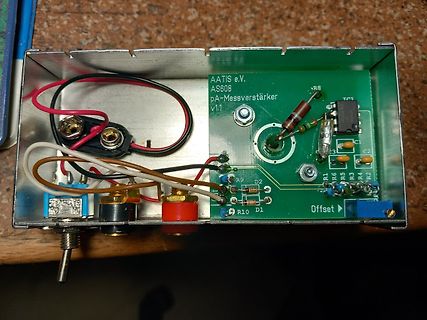
Geöffnetes Gehäuse mit Leiterplatte und Verkabelung
AATIS e.V. AS808 pA-Messverstärker v1.1 R8 IC1 C2 C3 R1 R6 R5 R4 R2 R9 D2 Offset D1 R10
-
Thread
April-Scherz 2026 in der ct
Bradward B. schrieb im Beitrag #8025676: > Die Nerd-Scherze der vergangen Jahre die CT seit AS behauptet hat man mußte die 9-pol. SIM-Module wechseln weil keine Ereiterung möglich ist, dabei war noch ein Pin frei für eine Vervierfachung des RAM-Bereichs.
-
 Bild
Bild
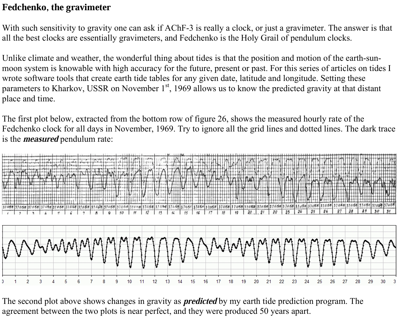
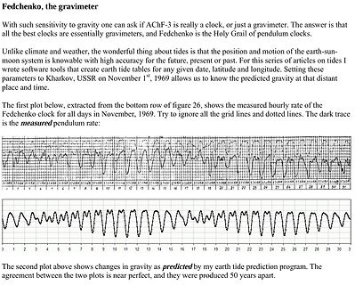
Text und Diagramme zur Gravitationsmessung
15 16 17 18 19 20 21 22 23 24 25 26 27 28 29 30 31 The second plot above shows changes in gravity as predicted by my earth tide prediction program. The agreement between the two plots is near perfect, and they were produced 50 years apart.
-
 Bild
Bild
Solarregler und Elektronikkomponenten in einem Gehäuse
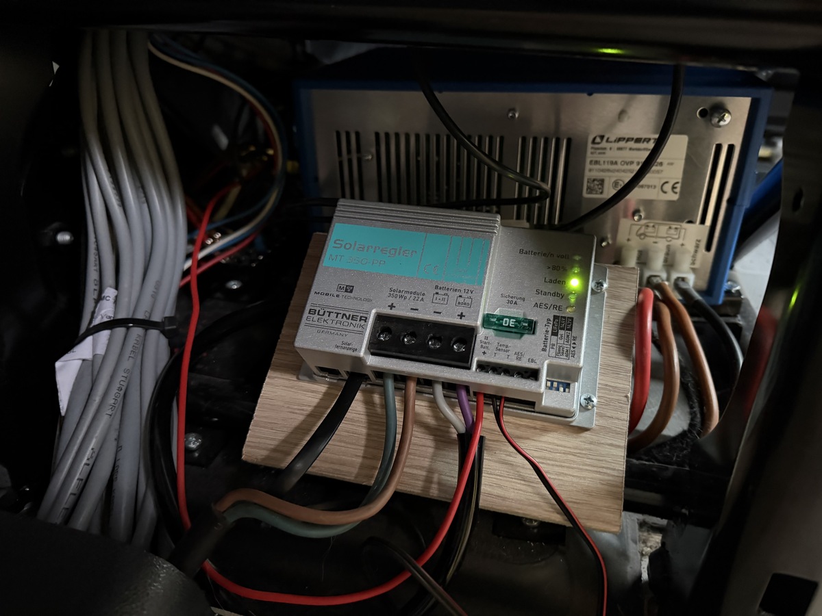
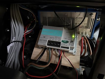
Solarregler MT 350-FP BÜTTNER ELEKTRONIK Solar Module 350W / 27A Batterien 12V Lader Standby Überladung AES/RE OE
-
 Bild
Bild
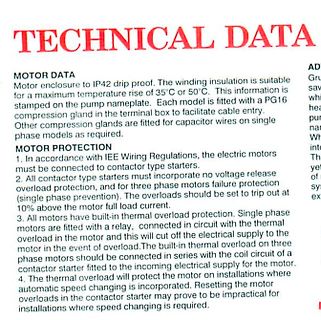
Ausschnitt technischer Daten zu Motoren
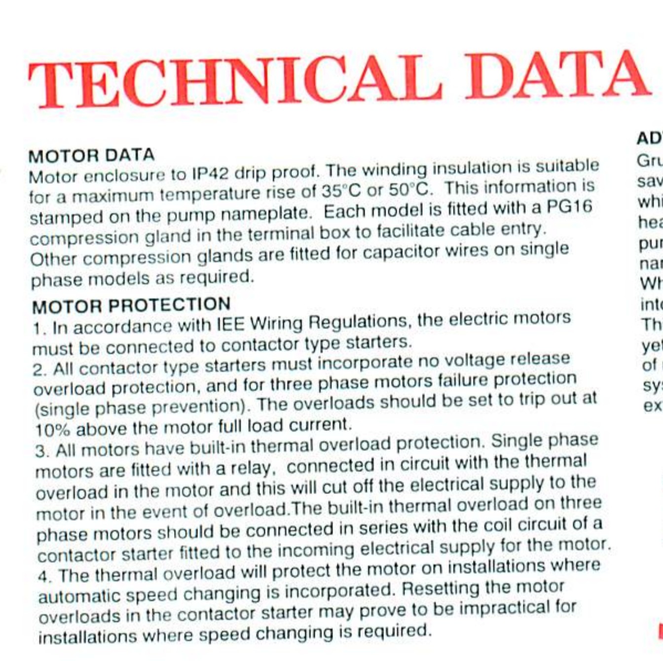
facilitate cable entry. Other compression glands are fitted for capacitor wires on single phase models as required. MOTOR PROTECTION 1. In accordance with IEE Wiring Regulations, the electric motors must be connected to contactor type starters. 2. All contactor type starters must incorporate no voltage release
-
Thread
Picoamperemeter Elektor
vom AATIS sehr zufrieden. Und der Preis passt ins Hobbybudget. https://www.aatis.de/content/bausatz/AS608_pA-Messverst%C3%A4rker
im aati-Dokument viel besser aus. Siehe hier: http://dl3hrt.darc.de/AATiS-Praxisheft_28-Dateien/AS608-Aufbauhinweise.pdf Und Flussmittelreste sieht man auch noch bei Dir. Gründlichst! abwaschen und dann die Platien mindestens über Nacht auf einen Heizkörper trocknen lassen. Du bist zufrieden