Hallo E34 L.-, E34 L. schrieb im Beitrag #7684168: > Was denn jetzt? Geht sie vor oder nach? wie ich schon schrieb: > meine neu gekaufte Armbanduhr geht pro Monat etwa 2 Minuten vor. Sie geht vor. Ich
irmp-20kHz: Version für 20kHz Scans Aufruf von IRMP. Der Aufruf geschieht dann über: ./irmp-nnkHz [-l|-p|-a|-v] < scan-file Die angegebenen Optionen schließen sich aus, das heisst, es kann jeweils nur eine Option zu einer Zeit angegeben werden: Option: -l List gibt eine Liste der Pulse und Pausen aus
libraries e ay o r x ej y o o ftd h e sp r y 2 s k r lr k i d d r k es n n s p oe t i r a d b ti t a e l e i n da t a r m l a hd r f - o a r tr r s o p r thatareoftennotinter-operablewithautomatedtestingtools. Gam- oa a - a a l r yi s i m - w h la a s o g s l wt s a p w l a on t e e l ff ing apps constitute
DESCRIPTION AND CONFIGURATION FIGURE 2-1: 32-PIN 5 MM X 5 MM QFN ASSIGNMENT, (TOP VIEW) I I 1 D N L N D_ E I D G C O S D L S V D S S C V 32 31 30 29 28 27 26 LED0 1 24 DGND PME 2 23 VDD_D1.8 INTRN 3 22 DGND DGND 4 Paddle Ground on 21 X2 VDD_CO1.8 5 Bottom of Chip 20 X1 EDD_IO 6 19 RSTN EESK 7 18 AGND
transition between nose piece and rear of transceiver K 56.5 Reference Transceiver overall length L 1.1x45° Minimum Chamfer on bottom of housing M 2.0 ± 0.25 Height of rear shoulder from transceiver printed circuit board N 2.25 ± 0.1 Location of printed circuit board to bottom of transceiver P 1.0
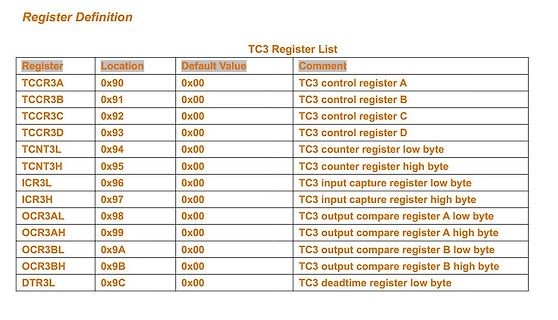
Register List
Register Location Default Value Comment
TCCR3A 0x90 0x00 TC3 control register A
TCCR3B 0x91 0x00 TC3 control register B
TCCR3C 0x92 0x00 TC3 control register C
TCCR3D 0x93 0x00 TC3 control register D
TCNT3L 0x94 0x00 TC3 counter register low byte
TCNT3H 0x95 0x00 TC3 counter register high byte
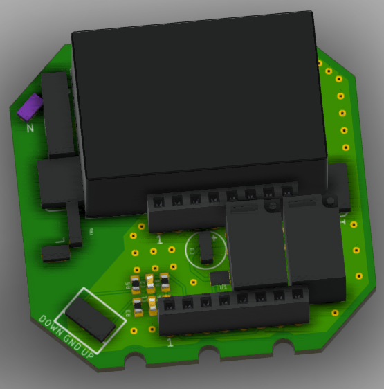
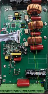
Spannungsversorgung: -Einsatz von Solid-State-Relais bei K1 -LC Filter am Ausgang bei Klemme 1+2 (L =1mH, 10nF aus Grenzfrequenz von 50kHz) -TVS Diode 24V beim LED-Treiber (+/-) Vorschlag zur Reduktion der Spannungsspitzen beim PWM Signal: -TVS Diode 24V beim LED-Treiber (Dim/-) -RC-Glied
R=50R, C=10nF aus Grenzfrequenz von 500kHz) LED-Treiber: https://irp-cdn.multiscreensite.com/91d0906f/files/uploaded/micro.pdf Was meint ihr, lösen diese Massnahmen mein Problem? Oder hat jemand noch ein anderer Ansatz bzw. Idee? Mfg Adrian
PHONES 29 VBIAS 45 SPDIFI 14 CS 30 AVSS1 46 MUTER 15 SK 31 HPOL 47 MUTEP 16 DR 32 HPOR 48 SPDIFO 1 R L R L R L S A FD RL R R S S P P V B R V II F F R R H H A V V A LL 36 35 34 33 32 31 30 29 28 27 26 25 AVDD2 37 24 MICR SSOL 38 23 MICL SSOR 39 22 AVSS3 CENO 40 21 DVDD1 LFEO 41 CM6206 20 REGV VOLUP2 43
file mcurses.h - include file for mcurses lib * * Copyright (c) 2011-2014 Frank Meyer - frank(at)fli4l.de * * This program is free software; you can redistribute it and/or modify * it under the terms of the GNU General Public License as published by * the Free Software Foundation; either version 2 of
----------- * @file mcurses.c - mcurses lib * * Copyright (c) 2011-2014 Frank Meyer - frank(at)fli4l.de * * This program is free software; you can redistribute it and/or modify * it under the terms of the GNU General Public License as published by * the Free Software Foundation; either version 2 of
C CL L DCtoC LtoL C C L L D L L L L L L L L L L L L C C F F C C F F DimensionLtoLures C tC L L C C CLtCL C tC L L C C L L L L L L L L A A E A A E A A E E E E B B B B B B A A C J J C J J E H E H D D D D D D Figure 3 Figure 4 C C F F C C F F C C F F CtoC LtoL C C L L C tC CLtCL C C L L C tC L tL C C L L L L L L L L L L L L L L Figure 1 Figure 2 A A E E A A E E DimenAions andWeights A B B J J C C Dimensions in Millimeters (InchesB Part J J E H B Device Mass
before the end of one switching period in the case of the DCM operation, there is a resonance between L m and C of the MOSFET. OSS V ds Snubber design Vsn nV o The excessive voltage due to resonance between L and lk1 C OSS should be suppressed to an acceptable level by an addi- V in tional circuit to protect
VI VA ir ad iocom andiI (complesso radiocomtto nli) iAlero osi Se i rvse, l lto mucchivchie itechevee utto l oio nolno ninsot, l numer/66 i CD,tete vederl'tnadi oetna a esnazoe ela aa neta l tema «Radioco;gracheucté itrsedi li etn,echeebbe utresnecocusoe conapesnazoedel prirgetovnet
. . . 5 4 - 2 Selection of Satellite (RUN MODE) . . . . . . . . . . . . . . . . . 5 1 G E N E R A L The ROBOT ANTENNA POSITIONER system selectedbroadcastingsatelliteisachieved. a parabolic antenna by a Robot Positioner. The advanced electronics technology, in- system allows the user to automatically
von 8-10V angelegt Es gibt 8V~ Relais, aber sie sind si selten wie deines und teuer Eltako R91-100-8V Daher wurde ich vorschlagen, du baust es dir aus 3 Bauteilen selber: https://www.kessler-electronic.de/de/DIP121A7212L https://www.kessler-electronic.de/de/Bauelemente/Halbleiter-diskret
°C, 170 270 Switching Mode V DD< V TH:LSM2.0 V) V DD= 3.0 V, FCLKOUT= 32.768 ΔIDD:CK32 1 µA kHz, C L 10 pF ΔI V DD= 3.0 V, FCLKOUT= 1024 Hz, 30 DD:CK1024 (6) C L 10 pF Additional VDDsupply current V = 3.0 V, F = 64 Hz, ΔIDD:CK64 DD CLKOUT 2 nA C L 10 pF V DD= 3.0 V, FCLKOUT= 1 Hz, ΔIDD:CK1 C = 10 pF 0.03 L (1)Fully operating. (2) Clocks operati2g, RAM registers retained and V LOW sampling working, but temperature sensing and compensation is stopped, CLKOUT is LOW and the I C interface is disabled (VDD
Different Sleep Modes Active Clock Domains Oscillators Wake-up Sources e t b k c d s u r d U S C Y l e s e a r r / r I w i C L k A A C r r b : d e M D t r f D l l c l l i o e n 2 A i S A I t S D c c c c a S i E N I T T O O M T I T W B Sleep Mode Idle X X X X X(2) X X X X X X X (2) X( ADCNRM X X X X
Un5&itmprp=enc%3AAQAJAAAA4AJ4PyjcdaDBzl4szgEdZPTSsCvqldGnmk2DwyJDmAQYToDcu%2BvwuB%2BtbiM%2F8NT1QLs4I6l%2BwyO9%2BhIxb91xWYhKvgVWdu0QmesQw5QgZOm9lIACyju%2FYZ61ww33d0ydswAh3u1b6mAxJdRHKnooVIlUjg8Hd15Fg6%2BSQWLQdXjrSoRgk3f459%2Fy12p97XEBcbH0uhNb%2FqKigNESQ4qz8NOB%2BMFDAgql%2FTsnR7cQ38HuVBBCh6Q8sPqsWMoT622090qfQ4DGQ97FyCCz1%2FOO1ivjQekb5Zu9PeSEYAd50qHn%7Ctkp%3ABk9SR6bL9onoYw Aber von Direktimporten aus CHN halte ich wenig und anscheinend bräuchte man aber noch eine Crimpzange - aber welche?! Ansonsten ginge das in die richtige Richtung. Man wäre flexibel mit
G. L. schrieb im Beitrag #7659256: > Ich versuche gerade eine i2c-Schnittstelle für einen Atmega328P auf > einem Arduino Uno über Interrups zu programmieren Dieser AVR hat I2C in Hardware, die sollte
G. L. schrieb im Beitrag #7659316: > Das geht schon mal um einiges flotter. Da fehlt aber der reti, oder? LG, Sebastian
..continued ) / , n 4 4 8 8 2 2 8 8 2 ( a n 4 S T N P N P N P I C P e c C C n C D R I (n A A B D Y L F Q F Q F Q D O S a p D P A A C A S W C C C C V L V T V T V T S S S n S A D Z U T T T T T E C i C P 1,AINP2 30 24 14 10 PD4 AIN4 X20/Y20 WO4 (3) 2,AINP1 31 25 15 11 PD5 AIN5 X21/Y21 1,AINN0 WO5 (3) 0
Espressif dabei auf das unter der URL https://forms.office.com/pages/responsepage.aspx?id=_SevX1c1lEKVRY6nSkCfOeLV_SQpKUFEtiN9wqjVAPFUMURZSVJSSzI1QldNV1pMM1EwTldKTEZUWS4u&ct=t(EMAIL_CAMPAIGN_4_29_2024_11_51)&mc_cid=5f81b916a8&mc_eid=3ede91cde2 bereitstehende Formular. ### Lieferkettengesetz verabschiedet
this technique, they could recover 100 percent of the glass fiber, 98 percent of the vitrimer, and 91 percent of the solvent for reuse. Unlike traditional plastics, vitrimer is not degraded by recycling, so it can be reused indefinitely. [/c] Zum Zeitpunkt der Drucklegung verspricht das Forscherteam
Dann gehe doch einfach mal nach der Lösung vor und gib uns die Ausgabe von efibootmgr -v ls -l /boot/efi/EFI/debian cat /boot/efi/EFI/debian/grub.cfg Vielleicht hast Du so installiert, dass die EFI Partition vom USB-Stick verwendet wird? mount | grep boot
ungefähr gleich bleibt. IC5 und Rechts“ verstärkt werden. Die Gleichung, IC6 bilden aus den Signalen L+ R und L- die dies ausdrückt, sieht wie folgt aus: R die Ausgangssignale. (L+R)+(L-R)=2·L und (L+R)-(L-R)= Falls erwünscht oder notwendig, können 2·R die Eingangs- und Ausgangssignale über Koppelkondensatoren
und ebenfalls 5 Stück bei UHF (K22 wegsperren!). 3*auf BT und 2 Fallen auf TT. Damit war sogar in L mit etwas Aufwand die 23 zu empfangen! Bei Krumpe in MW war diese Stückzahl üblich.
Hier eine Leiterplatte Schieberegister_mit_Treiber. Da noch geätzt wurde, könnte es 1990/91 gewesen sein. Für Relaisansteuerung oder Leuchtdioden. Soll jetzt als Demo nochmals aktiviert werden, aber erst wenn ich wieder besser sehen kann. Die Karte wurde mit Bitwackeln von den damaligen
FORTH AT www.vishay.com/doc?91000 Outline Dimensions www.vishay.com Vishay Semiconductors TO-247AD 2L DIMENSIONS in millimeters and inches (3) A A E (6F P (Datum B) B S A2 Ø K M D BM (2) R/2 F P1 A D2 Q 2 x R D1 (4) (2) D 1, 2 3 D 4 Thermal pad (5) L1 C (4) L See view B E1 A 0.01M D BM View A - A 2 x
Z80 Befehlssatz bleiben lieferbar und sind nicht abgekündigt. Z.B. der Z8018010FSG oder der EZ80F91AZA50EK https://www.mouser.de/c/semiconductors/embedded-processors-controllers/microprocessors-mpu/?q=PCN%20Littlefuse&core=Z80 https://www.mouser.de/c/semiconductors/embedded-processors-controllers
CP/M 3.1 using yaze-ag ... Loading CP/M 3.1 ... 62K TPA DRIVES: A B C/ D . F G H I J K L M N O . CP/M 3.1 BIOS for yaze-ag, V 1.11 22.05.2019, Copyright (c) by A.Gerlich A> [/code]
von der Ästhetik abhängig machen. Mit freundlichem Gruß: Bernd Wiebus alias dl1eic http://www.l02.de
Harry L. schrieb im Beitrag #7651029: > Schau mal hier vorbei! > https://audiocreativ.de Jedenfalls stabiler als die Kiste von Amazon :) Preis geht aber noch. (165mm Höhe, 91 Euro ) Danke für den Link

 Bild
 Bild
 Bild

 Bild
 Bild
 Bild
 Bild
 Bild
 Bild
 Bild