-
PDF
e_ek01_passhi.pdf
Reflective type Transmissive type Transmissive type Duty Item Conditions 1/N Unit Remarks Min. Typ. Max. Min. Typ. Max. Min. Typ. Max. 64 –20 30 –20 30 –20 30 deg. Viewing Angle 100 –20 30 –20 30 –20 30 CR>1.4 θ (φ, 0˚–180˚) 200 –20 20 –20 20 –20 20 240 –20 20 –20 20 –20 20 (Note 1) (Note 2) 64 –30 30
in „LCD Displays ohne Bezeichnung“ · Mikrocontroller und Digitale Elektronik ·
-
PDF
BTHQ_128064AVD-FSTF-12-LED02White-COG.pdf
PAGE 4 OF 18 Specification of LCD Module Type Model No.: COG-BTD12864-04 1. General Description x▯ 128 x 64 Dots FSTN Positive Black & White Transflective Dot Matrix LCD Module. x▯ Viewing Angle: 12 o’clock direction. x▯ Driving duty: 1/65 Duty, 1/7 bias. x▯ ‘Epson’ S1D10605D04B (COG) Dot Matrix LCD
in „Einschaltproblem“ · Mikrocontroller und Digitale Elektronik ·
-
PDF
Datenblatt_Display.pdf
01 REV. A (BTHQ 128064AVD-SRE-06-COG) JULY/2003 PAGE 7 OF 16 32 COG-BTD12864 LCD GRAPHIC DISPLAY 32 128X64 DOTS 8 1 RES CS1 D/C R/W(WR) E(RD) D7~D0 8 DOT MATRIX VDD LCD VSS CONTROLLER/ VOUT DRIVER C3- 'EPSON' C1+ S1D10605D04B C1- (COG) C2- C2+ V1 V2 V3 V4 V5 C86 P/S Figure 3: Block Diagram. DATA MODUL
in „Pixelfehler auf Graphikdisplay“ · Mikrocontroller und Digitale Elektronik ·
-
Datei
WebRadio.ino
*********************************************************/ char url[] = "http://st01.dlf.de/dlf/01/128/mp3/stream.mp3"; // Deutschlandfunk //char url[] = "http://rbb-antennebrandenburg-live.cast.addradio.de/rbb/antennebrandenburg/live/mp3/128/stream.mp3\0"; //char url[] = "http://138.201.252.6/brf_128
in „Webradio basteln“ · Mikrocontroller und Digitale Elektronik ·
-
PDF
ml280epson_tcm3-37706.pdf
die Anzahl Spalten. 8-14 Kapitel 8: Punktadressierbare Grafiken Erste Byte 1 2 3 4 5 6 7 8 9 10 11 128 64 t e 32 w n 16 t s P 8 4 2 1 0 1 2 5 1 0 20 40 80 160 64 128 Zweites Byte 3 5 9 1 2 4 6 7 8 10 11 128 64 t e 32 s o 16 i o P 8 4 2 1 128 0 128 0 0 0 0 0 0 0 0 8-15 Kapitel 8: Punktadressierbare Grafiken Nachfolgend ein Beispielprogramm: 10 REM 9-Nadel-Grafikdemo 20 : 30 DATA 0, 128, 1, 0, 2, 128, 5, 0, 10, 0, 20, 0, 40, 0, 80, 0, 160, 0, 64, 0, 128, 0 40 REM Musterdaten 50 : 60 RESTORE 70 WIDTH "lpt1:", 255 80 : 90 FOR I = 1 TO 22:REM Grafikzeichenfolge gene- rieren 100 READ A
-
PDF
RG12864K-BIW-VBG.pdf
1.General Specification The Features is described as follow: ◼ Module dimension: 93.0 x 70.0 x 13.(max.) mm ◼ View area: 72.0 x 40.0 mm ◼ Active area: 66.52 x 33.24 mm ◼ Number of dots: 128 x 64 ◼ Dot size: 0.48 x 0.48 mm ◼ Dot pitch: 0.52 x 0.52 mm ◼ LCD type: STN Negative, Blue Transmissive, ◼ Duty
in „LCD U8g2 asm“ · Mikrocontroller und Digitale Elektronik ·
-
Datei
rf12.c
portbits.h> #include "global.h" #include "rf12.h" #define F_CPU 16000000UL #include "delay.h" #define MAX_BUF 128 // Paket Größe in Bytes (maximal 250) #define ANSWER_TIMEOUT 15 // Maximale Wartezeit auf die Bestätigung der Daten in ms (max 500) #define RETRY 50 // Maximale Anzahl an Sendeversuchen #define
in „Bausatz Add-on für AVR-NET-IO“ · Mikrocontroller und Digitale Elektronik ·
-
Datei
fehler.txt
dependencies for file: C:\Users\Judith\Documents\Arduino\libraries\U8glib\src\clib\u8g_dev_ssd1351_128x128.c Using cached library dependencies for file: C:\Users\Judith\Documents\Arduino\libraries\U8glib\src\clib\u8g_dev_ssd1353_160x128.c Using cached library dependencies for file: C:\Users\Judith\Documents
in „Marlin auf anet e12“ · Mikrocontroller und Digitale Elektronik ·
-
PDF
PWM_Controller_Manual.pdf
Speicherreservierungen SRAM Adresse [*16] Größe[Byte] Bottom SRAM Start Reserviert für RX Befehle TOP 128 TWI Receive Buffer Bottom E0 128 TOP TWI Transmitt Buffer Bottom 160 128 TOP Bottom Temporary 32 TOP Bottom Daten Speicher 480 TOP Stack Bottom RAMEND- 128 128 TOP RAMEND EEPROM Adresse [*16] Größe[
in „PWM- Controller 18- Kanal TWI- Bus Proj.“ · Projekte & Code ·
-
Datei
Projet_07_Akkulader.asm
spannungsteiler der Ladeschaltung ;PORT D ; ;pin2 (PD0) : ist der pin um daten zur empfangen auf --->MAX232 ;pin3 (PD1) : ist der pin um daten zur senden auf ---->MAX232 ;pin6 (PD4) : ist der pin um ein impuls auf die ladeschaltung zu geben um die Akkus zu entladen ; (wird bei reflexverfahren benutzt)
in „Wichtig: was ist hier im AVR programm falsch??“ · Mikrocontroller und Digitale Elektronik ·
-
Datei
main.c
kurzen Tastendrucks */ #define ADCSUM 8*ADCTRIGGER /* Ereignissumme */ #define ABGVEKTORDIM 20 /* Max Zahl der Stuetzstellen der Tankfuellung */ #define DRMITTELDIM 16 /* Stuetzstellenzahl Mittelwertbildung */ #define TIMEIRQ 8 /* Multiplikator Timerticks bis 1/10s */ /* key task Byte */ #define keypressed
in „Benzintank Füllstand mittels Drucksensor“ · Analoge Elektronik und Schaltungstechnik ·
-
Datei
avr_f64.c
digits in the mantisse in order to // get a maximum string width of 'max_nr_chars' chars. If however max_nr_chars is so small that // even a mantisse of one digit and the corresponding exponent doesn't fit into 'max_nr_chars' chars, // the string returned will be longer
in „64 Bit float Emulator in C, IEEE754 compatibel“ · Projekte & Code ·
-
PDF
MX25L12805D__3V__128Mb__v1.2.pdf
Acceleration mode: - Chip erase time: 50s (typical) • Low Power Consumption - Low active read current: 25mA (max.) at 50MHz - Low active programming current: 20mA (max.) - Low active erase current: 20mA (max.) - Low standby current: 20uA (max.) - Deep power-down mode 20uA (max.) • Typical 100,000 erase/program
in „FLASH Memory Chip im Lenovo X200 von 8 MB auf 16 MB vergroessern“ · PC Hard- und Software ·
-
Datei
FIR.py
- 1024 schrittweite += 1 max_ungefiltert = max(ungefiltert) gefiltert = [] schieberegister = [0]*len(koeffizienten) for i in range(0,len(ungefiltert)): schieberegister.pop(0) schieberegister.append(ungefiltert[i]) summe = 0 for
in „Pyfda und die Amplitude“ · Digitale Signalverarbeitung / DSP / Machine Learning ·
-
Datei
ADC_Trigger.c
F_INT 400.0 // Interruptfrequenz für Abtastung #define VORTEILER 256.0 // Vorteiler Timer 0 #define MAX_T0 (uint8_t)(((F_CPU/(VORTEILER*F_INT)))-0.5) #define LEDRT 3 // Port D rote LED #define LEDGN 4 // Port D grüne LED uint16_t messwert; //------------------------------------------------------------
in „ATMega328P ADC Fehler im Datenblatt?“ · Mikrocontroller und Digitale Elektronik ·
-
PDF
man_gcc.pdf
", "atxmega128a3u", "atxmega128b1", "atxmega128b3", "atxmega128c3", "atxmega128d3", "atxmega128d4", "atxmega192a3", "atxmega192a3u", "atxmega192c3", "atxmega192d3", "atxmega256a3", "atxmega256a3b", "atxmega256a3bu
in „avr-g++: external linkage von const/PROGMEM Symbol.“ · Mikrocontroller und Digitale Elektronik ·
-
Datei
twi_lib.h
4 // Max number of TWI Software channels requiring different transmission rates #define conTwiMaxErrorBuffer 25 // Max numbe of Errors that can be stored in TWI Error Buffer #define conTwiTimeOut 15 // TimeOut
in „TWI MUX per SW an einem Port“ · Mikrocontroller und Digitale Elektronik ·
-
PDF
138720_DS.pdf
MONITOR CHARACTERISTICS Power Supply Trip Point Accuracy ±2.5 %of Selected Nominal Trip Point Voltage max ±1.0 ±1.0 %of Selected Nominal Trip Point Voltage typ DIGITAL INPUTS Input High Voltage INH) 2.4 V min Input Low Voltage (INL 0.8 V max Input Leakage Current (Port0, EA) ±10 µA max VIN= 0 V or DD ±1 ±1 µA typ VIN 0 V or VDD Logic 1 Input Current (All Digital Inputs) ±10 µA max VIN= VDD ±1 ±1 µA typ VIN V DD Logic 0 Input Current (Port 1, 2, 3) –80 µA max –40 –40 µA typ VIL= 450 mV Logic 1-0 Transition Current (Port 1, 2, 3) –700 µA max VIL 2 V –400 –400 µA typ V = 2 V IL
in „aduc812bs Wie programmieren?“ · Mikrocontroller und Digitale Elektronik ·
-
Datei
Hilfe_wo_ist_der_Fehler_.txt
send_buf[5]=0b00001000; //Checksumme Low-Byte // send_buf[6]=0x0d; //END ROUTINE (ETX) /*_________MAX3082 TRANSMITTING__________*/ //RS485_SENDEN_RE = 0; //RS485_SENDEN_DE = 1; /*___________Warte auf MAX3082___________*/ //for(i=0;i < 1000; i++); /*___________Senden___________*/ i=0; for(i=0;i<=0;i+
in „Fehler im Programm Slave versteht Master nicht“ · Mikrocontroller und Digitale Elektronik ·
-
PDF
OLED_Display_1_12.pdf
2017-05-14 3 PHYSICAL DATA No. Items: Specification: Unit 1 Diagonal Size 1.12 Inch 2 Resolution 128(H) x 128(V) Dots 3 Active Area 20.14(W) x 20.14(H) mm² 4 Outline Dimension (Panel) 27.00 (W) x 30.10(H) mm² 5 Pixel Pitch 0.1575(W) x 0.1575(H) mm² 6 Pixel Size 0.1375(W) x 0.1375(H) mm² 7 Driver IC
in „SH1107G Beschaltung“ · Mikrocontroller und Digitale Elektronik ·
-
Datei
Configuration.h
#define Z_MIN_ENDSTOP_INVERTING true // set to true to invert the logic of the endstop. #define X_MAX_ENDSTOP_INVERTING false // set to true to invert the logic of the endstop. #define Y_MAX_ENDSTOP_INVERTING false // set to true to invert the logic of the endstop. #define Z_MAX_ENDSTOP_INVERTING false
in „Marlin Firmware mit dem ATMEL STUDIO 7 auf das Arduino Mega 2560 Board flashen“ · Mikrocontroller und Digitale Elektronik ·
-
Datei
Configuration.h
#define Z_MIN_ENDSTOP_INVERTING false // set to true to invert the logic of the endstop. #define X_MAX_ENDSTOP_INVERTING false // set to true to invert the logic of the endstop. #define Y_MAX_ENDSTOP_INVERTING false // set to true to invert the logic of the endstop. #define Z_MAX_ENDSTOP_INVERTING false
in „Marlin Firmware mit dem ATMEL STUDIO 7 auf das Arduino Mega 2560 Board flashen“ · Mikrocontroller und Digitale Elektronik ·
-
 Bild
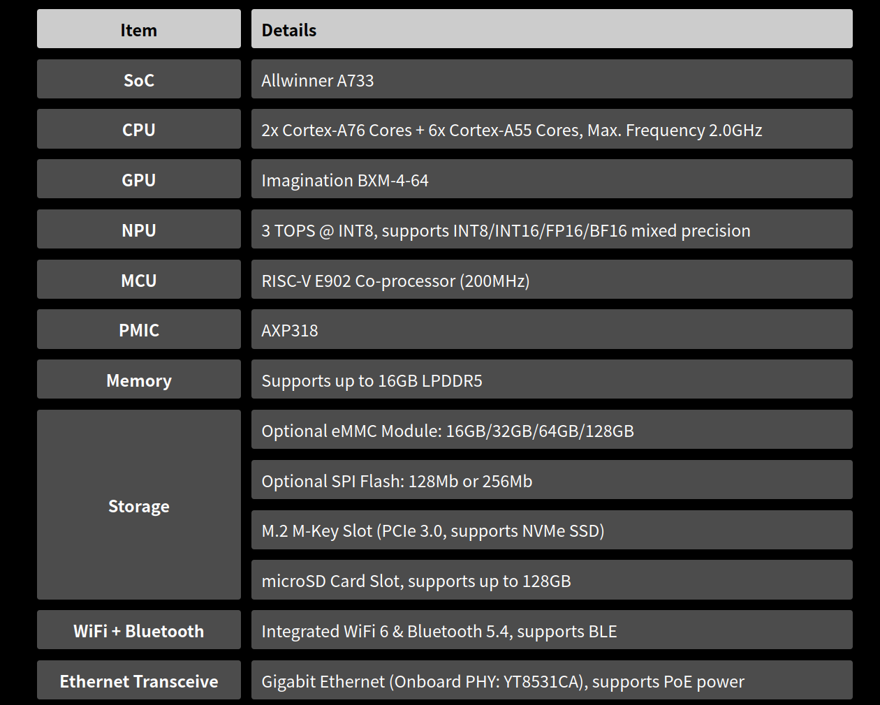
Spezifikationsliste eines Allwinner A733 SoC
Item Details SoC Allwinner A733 CPU 2x Cortex-A76 Cores + 6x Cortex-A55 Cores, Max. Frequency 2.0GHz GPU Imagination BXM-4-64 NPU 3 TOPS @ INT8, supports INT8/INT16/FP16/BF16 mixed precision MCU RISC-V E902 Co-processor (200MHz) PMIC AXP318 Memory Supports up to 16GB LPDDR5 Storage Optional eMMC Module: 16GB/32GB/64GB/128GB Optional SPI Flash: 128Mb or 256Mb M.2 M-Key Slot: PCIe 3.0, supports NVMe SSD microSD Card Slot, supports up to 128GB WiFi + Bluetooth Integrated WiFi 6 & Bluetooth 5.4, supports BLE Ethernet Transceive
in „Neuer OrangePi, neue Mikrocontroller und dazugehörende Software“ · Mikrocontroller und Digitale Elektronik · · Screenshots
-
PDF
KM416C1204C.pdf
128 128 128 ms Write command set-up time WCS 0 0 0 ns 7 CAS to W delay time CWD 28 32 36 ns 7,13 RAS to W delay time RWD 59 67 79 ns 7 Column address W delay time AWD 37 42 49 ns 7 CAS precharge to W delay
in „Suche DRAM Chips“ · Mikrocontroller und Digitale Elektronik ·
-
Datei
Dotmatrix.c
) MaxAdress=0x04; if (Zeile==1) MaxAdress=0x05; for(I=0;I<8;I++) //Übtragung seriell an MAX { Tmp=MaxAdress; MaxAdress&=0x80; MaxAdress>>=7; PORTD=MaxAdress; //DIN PORTD|=0x02; //CLK PORTD=0x00; MaxAdress=Tmp; MaxAdress<<=1; } for(I=0;I<8;I++) { Tmp=MaxData; MaxData&=0x80; MaxData>>=7; PORTD=MaxData; //DIN PORTD|=0x02; //CLK PORTD=0x00; MaxData=Tmp; MaxData<<=1; } for(I=0;I<Shift;I++) //daten in hinteren MAX
in „Von Arrays zu einem String“ · Mikrocontroller und Digitale Elektronik ·
-
Datei
mmc.c
data spi_io_mem(buffer,6); }; // gets a 1 byte long R1 static u08 MMC_get_R1(void){ u08 retval; u08 max_errors = 128; // wait for first valid response byte do{ retval = spi_io(0xff); max_errors--; }while( (retval & 0x80) && (max_errors>0)); return retval; }; // gets a 2 byte long R2 static u16 MMC_get_R2(void){ u16 retval; u08 max_errors = 64; // wait for first valid response byte do{ retval = spi_io(0xff); max_errors--; }while( (retval & 0x80) && (max_errors>0) ); // move data to upper byte retval = (retval << 8); // get second
in „[atmega8] UART-Daten auf SD-Karte schreiben“ · Mikrocontroller und Digitale Elektronik ·
-
Datei
Configuration_adv.h
one or both of these to override the default 0-255 range. */ //#define FAN_MIN_PWM 50 //#define FAN_MAX_PWM 128 // @section extruder /** * Extruder cooling fans * * Extruder auto fans automatically turn on when their extruders' * temperatures go above EXTRUDER_AUTO_FAN_TEMPERATURE. * * Your board's pins
in „Marlin Firmware mit dem ATMEL STUDIO 7 auf das Arduino Mega 2560 Board flashen“ · Mikrocontroller und Digitale Elektronik ·
-
PDF
MLX81205-Datasheet-Melexis.pdf
MLX81206 MLX81208 MLX81205 MLX81207 Flash Memory [kByte] 32 64 32 64 RAM [kByte] 4 4 4 4 NVRAM [Byte] 1 4x128 4x128 4x128 4x128 Package QFN32 QFN32 TQFP48 TQFP48 Support of active high side No No Yes Yes reverse polarity protection Current shunt measurement High side High side High side High side possibility
in „Melexis Baustein“ · Mikrocontroller und Digitale Elektronik ·
-
PDF
Treiber_IC-SSD0323_OLED_128x64_GELB.pdf
selectable 6800-/8080- series compatible Parallel Interface or Serial Peripheral Interface. SSD0323 has a 128-step contrast control and a 16 gray level control. The embedded on-chip oscillator and DC-DC voltage converter reduce the number of external components. FEATURES Support max. 128 x 80 matrix panel Power
in „[Q]Erfahrungen mit (Reichelt) Pictiva OLED Displays“ · Mikrocontroller und Digitale Elektronik ·
-
PDF
an4545-vl6180x-basic-ranging-application-note-stmicroelectronics.pdf
tuning Changing the settings in this section can affect the performance of the overall system. 6.1.1 Max convergence time The SYSRANGE__MAX_CONVERGENCE_TIME {0x1c} register sets an upper limit for the max convergence time. See Figure 10. Figure 10. System timing diagram for a signal ranging measurement The max convergence time is made up of the convergence time and sampling period. By default the max convergence time is set to 49ms during device power-up. Reducing the max convergence time will reduce the
in „STM32F1 Probleme mit Frings I2C-Bus Routine“ · Mikrocontroller und Digitale Elektronik ·
-
PDF
Hargassner_Datenprotokoll_155_Pakete.pdf
KaskLZLeisMin_4/' unit=/'Min/'//> **** Kaskade Laufzeit Min Leistung 4 120 /'120/' name=/'KaskLZLeisMax_1/' unit=/'Min/'//> \ **** Kaskade Laufzeit Max Leistung 1 121 /'121/' name=/'KaskLZLeisMax_2/' unit=/'Min/'//> **** Kaskade Laufzeit Max Leistung 2 122 /'122/' name=/'KaskLZLeisMax_3/' unit=/'Min/'//> **** Kaskade Laufzeit Max Leistung 3 123 /'123/' name=/'KaskLZLeisMax_4/' unit=/'Min/'//> \ **** Kaskade Laufzeit Max Leistung 4 124 /'124/' name=/'Kask LZLeist_1/' unit=/'h/'//> **** Kaskade Laufzeit Lesitung 1 125 /'125/'
in „Hargassner Pelletheizung Betriebsdatenerfassung“ · Haus & Smart Home ·
-
PDF
Hargassner_Datenprotokoll_155_Pakete.pdf
KaskLZLeisMin_4/' unit=/'Min/'//> **** Kaskade Laufzeit Min Leistung 4 120 /'120/' name=/'KaskLZLeisMax_1/' unit=/'Min/'//> \ **** Kaskade Laufzeit Max Leistung 1 121 /'121/' name=/'KaskLZLeisMax_2/' unit=/'Min/'//> **** Kaskade Laufzeit Max Leistung 2 122 /'122/' name=/'KaskLZLeisMax_3/' unit=/'Min/'//> **** Kaskade Laufzeit Max Leistung 3 123 /'123/' name=/'KaskLZLeisMax_4/' unit=/'Min/'//> \ **** Kaskade Laufzeit Max Leistung 4 124 /'124/' name=/'Kask LZLeist_1/' unit=/'h/'//> **** Kaskade Laufzeit Lesitung 1 125 /'125/'
in „Hargassner / Rennergy Touchtronic Netzwerkanbindung/Visualisierung“ · Haus & Smart Home ·
-
Datei
lcdcon_ft245_4bit.asm
Das MSB jedes Pixels * ;* beginnt an der normalen Adresse, das LSB an der Spalten Adresse * ;* plus 128. (Bsp: XStart=0: MSB Beginn=0, LSB Beginn=128, * ;* XStart=28: MSB Beginn=28, LSB Beginn=156 * ;* * ;* 009 Schwarzweismodus (Standart). Schaltet die Ausgabe auf SW um. * ;* * ;* 011 Clear LCD. Dieser
in „LCD Controller für 640x480 LCD mit mega8515“ · Projekte & Code ·
-
PDF
W78E051C40DL_4170039.pdf
W78E051C 10. PACKAGE DIMENSIONS 10.1 40-pin DIP Symbol Dimension in inch Dimension in mm Min. Nom. Max. Min. Nom. Max. A 0.210 5.334 A 1 0.010 0.254 A 2 0.150 0.155 0.160 3.81 3.937 4.064 0.016 0.018 0.022 0.406 0.457 0.559 B 0.048 0.050 0.054 1.219 1.27 1.372 B 1 c 0.008 0.010 0.014 0.203 0.254 0.356
in „Winbond W78E051 programmieren - kennt ihr compiler? woher ISP?“ · Mikrocontroller und Digitale Elektronik ·
-
PDF
LCD64128A_DIS.pdf
--- LCD duty 1/64 --- LCD bias 1/9 --- Viewing direction 6 o’clock Module size (W×H×T) 93 × 70 × 14MAX (3.66″ × 2.76″ × 0.55″MAX) mm Viewing area (W×H) 70.7× 38.8 (2.78″ × 1.53″) mm Number of dots 128 × 64 dots Dot size (W×H) 0.48 × 0.48 (0.019″ × 0.019″) mm Dot pitch (W×H) 0.52 × 0.52 (0.020″ × 0.020
in „Grafikdisplay 64x128 reagiert nicht? brauche hilfe“ · Mikrocontroller und Digitale Elektronik ·
-
Datei
PI_Regler.h
multipliziert mit SCALING_FACTOR int16_t D_Factor; //! maximum allowed error, avoid overflow int16_t maxError; //! maximum allowed sumerror, avoid overflow int32_t maxSumError; } pidData_t; /*! \brief Maximum values * * Needed to avoid sign/overflow problems */ // Maximum value of variables #define MAX_INT INT16_MAX #define MAX_LONG INT32_MAX #define MAX_I_TERM (MAX_LONG / 2) void pid_Init(int16_t p_factor, int16_t i_factor, int16_t d_factor, struct regler_werte *pid_st); int16_t pid_Controller(int16_t sollwert
in „Funktion mit INOUT Variablen“ · Mikrocontroller und Digitale Elektronik ·
-
Datei
mmc.c
/* MMC Ansteuerung mit Hilfe einer Software SPI (C) 2006 Christian Kartengrösse: 128 MB Blocks 64MB: 0x08.00.00.00 (int32) Aufteilung in 4 x 16 MB = Bank 0 0x00.00.00.00 Bank 1 0x01.00.00.00 usw. max. Blocknummer pro Bank = 0xffff */ #ifndef _mmc_c #define _mmc_c #ifdef USE_MMC #include
in „Arduino oder doch lieber ein Keil NXP ARM Board?“ · Mikrocontroller und Digitale Elektronik ·
-
Datei
mmc.c
/* MMC Ansteuerung mit Hilfe einer Software SPI (C) 2006 Christian Julius Kartengrösse: 128 MB Blocks 64MB: 0x08.00.00.00 (int32) Aufteilung in 4 x 16 MB = Bank 0 0x00.00.00.00 Bank 1 0x01.00.00.00 usw. max. Blocknummer pro Bank = 0xffff */ #ifndef _mmc_c #define _mmc_c #ifdef USE_MMC #include
in „Verständnissprobleme mit der SD Karten- Speicherverwaltung“ · Mikrocontroller und Digitale Elektronik ·
-
Datei
mmc.c
/* MMC Ansteuerung mit Hilfe einer Software SPI (C) 2006 Christian Julius Kartengrösse: 128 MB Blocks 64MB: 0x08.00.00.00 (int32) Aufteilung in 4 x 16 MB = Bank 0 0x00.00.00.00 Bank 1 0x01.00.00.00 usw. max. Blocknummer pro Bank = 0xffff */ #ifndef _mmc_c #define _mmc_c #ifdef USE_MMC #include
in „Retro Fieber: Z80 oder 68000 ?“ · Mikrocontroller und Digitale Elektronik ·
-
Datei
main.c
Flash char noch_ein_Flash_String[] PROGMEM = "Iam Nr. two"; // Sinusfunktion; Eine volle Periode = 128 Punkte uint8_t sinus[128] PROGMEM = { 16, 17, 18, 18, 19, 20, 21, 21, 22, 23, 24, 24, 25, 26, 26, 27, 27, 28, 28, 29, 29, 30, 30, 30, 31, 31, 31, 32, 32, 32, 32, 32, 32, 32, 32, 32, 32, 32, 31, 31,
in „LCD 162D mit ATmega8535“ · Mikrocontroller und Digitale Elektronik ·
-
Datei
main.c
Flash char noch_ein_Flash_String[] PROGMEM = "Iam Nr. two"; // Sinusfunktion; Eine volle Periode = 128 Punkte uint8_t sinus[128] PROGMEM = { 16, 17, 18, 18, 19, 20, 21, 21, 22, 23, 24, 24, 25, 26, 26, 27, 27, 28, 28, 29, 29, 30, 30, 30, 31, 31, 31, 32, 32, 32, 32, 32, 32, 32, 32, 32, 32, 32, 31, 31,
in „Display nach Tutorial Probleme“ · Mikrocontroller und Digitale Elektronik ·
-
PDF
Spec_LCM-198-05_Rev_C_DMO.pdf
Data Modul AG - www.data-modul.com 5 LCM198-05 GRAPHIC LCD 32 32 DISPLAY 128 x 64 DOTS 8 1 VSS VDD E/RD LCD DRIVER & RW/WR CONTROLLER A0 RES 'NOVATEK' CS1 NT7534H IS1 (TAB) IS2 D0~D7 8 LED_A Amber LED04 backlight Figure 2: Block Diagram Data Modul AG - www.data-modul.com 6 3
-
PDF
vs1011.pdf
connecting other devices to it. 4.8 Switching Characteristics - DREQ Signal Parameter Symbol Min Typ Max Unit Data Request Signal DREQ 200 ns 4.9 Switching Characteristics - SPI Interface Output Parameter Symbol Min Typ Max Unit SPI Input Clock Frequency CLKI MHz 6 Rise time for SO 25 ns Note: Maximum
-
PDF
ISL88731.PDF
, F is the Acknowledge. The master then sends the higher data byte to be IN,MAX SW written into the desired register. The ISL88731 will respond with switching frequency and I L,MAX is the max DC current in the an Acknowledge. The master then issues a Stop condition, inductor. indicating to the ISL88731 that the current transaction is For VIN,MAX = 20V, VBAT = 12.6V, IBAT,MAX = 4.5A, and complete. Once this transaction completes the ISL88731 will fs= 400kHz, the calculated inductance is 9.3µH. Choosing the begin operating at the new current
in „Chip gesucht“ · Mikrocontroller und Digitale Elektronik ·
-
Datei
MAX7219.c
#include "Max7219.h" //Max7129 Zeichentabelle const uint8_t chars[] = {126,48,109,121,51,91,95,112,127,123}; uint8_t black_digit = 9; void Load_Low(void) { PORTB &= ~(1 << PB2); } void Load_High(void) { PORTB |=
in „code ummodeln??“ · Mikrocontroller und Digitale Elektronik ·
-
PDF
EN_300744_DVBT.pdf
defined by the following. An (N -r1) bit binary word R' ii defined, with N = rog M 2 max, where M max = 2 048 in the 2K mode and M max = 8 192 in the 8K mode, where R' taies the following values: i = 0,1: R'i [Nr-2, Nr-3, ..., 1, 0] = 0, 0, ..., 0, 0 i = 2: R'i [Nr-2, Nr-3, ..., 1, 0] =
in „Frage nach günstiges Pegelmessgerät - Messprinzip über mehrere Frequenzen“ · HF, Funk und Felder ·