harmonic distortion At any level up to rated power, into 4 or 8 ohms <0.05% (20Hz – 20kHz) Typically <0.005% at 1kHz Frequency response +-0.2dB (20Hz – 20 kHz) -1dB at 1Hz and 100kHz Residual hum and noise Referenced to full
BD35F-HD and BD1.4F-VSD-HD are new versions the need for current batteries if an ice bank is used which can handle extreme vibrations. for energy storage.When storing the sun energy in ice packs the cabinet can be kept at desired BD35F-B (Bus-optimized) temperatures both night and day. The BD35F-B is a special
BEA-630 ATX-Netzteil von Bicker vor mir. https://www.bicker.de/bea-630_industrie_pc-netzteil_300w_90-264v_pfc_atx12v_ac-dc_ps2_24-7_62368-1 Dieses hat einfach plötzlich ausgeschaltet und ließ sich nicht mehr einschalten. Ob es dabei ein Knall oder sonstiges Geräusch gegeben hat, kann ich leider nicht
from Power Integrations and I found it to be defect following the traces from the mains and looking at the secondary of the rectified output from the transformer attached to this IC: the rectified output was not reaching a correct voltage, instead it was oscillating at a low voltage like if it was endlessly
2 G Sattler, DJ4LB 1973/2 66 - 80 Television 2 m Band A 144 MHz Linear Amplifier with 25 W Output at 12 V to 14 V G Otto, DC6HL 1973/2 81 - 90 Measuring A Dual Input Preamplifier with 2:1 Prescaler for Frequency Counters from W R Kritter, DL8TM 1973/2 91 - 94 Technology 1 Hz to Min 100 MHz Measuring
is write cycle. shifted out on the SO pin. Data stored in the memory at 6.1 SRAM/RTCC Registers the next address can be read sequentially by continuing to provide clock pulses to the client. The The RTCC registers are located at addresses 0x00 to internal Address Pointer
as low as 600 μA, and awakening via one- line control command - Support speed forward and backward at specific time - Support replay at specific time - Support specific starting time - Support BUSY signal output - Enable stable application via comprehensive command set - Tailor-made application for command
3 hours. electrochemically Test and visually Fully charge cells per 6.1.1, rest at 40±2℃ with 90%~ No appreciable Humidity alternation 3 95RH% for 48 hours. Then the cells are placed at room Test temperature to “dry out” for 2 hours. electrochemically and visually After standard charged
installation. • CPU CLOCK SETTING The system speed depends on the frequency of CLOCK GENERATOR. The user can change the clock selection jumper to set up the system speed at 25, 33 ,40MHz for different CPU speeds. The mainboard can use AMD5 x86, Cx5 8x, 80486DX, DX2, OverDrive, P24T, P24D and DX4 CPU, and the
analog signals without distortion. TYPICAL APPLICATIONS 4. High sensitivity, low ON resistance • Modem Can control a maximum 0.13 A load • Telephone equipment current with a 5 mA input current. Low • Security equipment ON resistance of 25Ω (AQY210EH). • Sensors TYPES Part No. Output rating* Through hole
Apps Can Quickly Destroy Your Mobile’s Flash: Why They Don’t, and How to Keep It That Way Tao Zhang Aviad Zuck The University of North Carolina at Chapel Hill Technion – Israel Institute of Technology zhtao@
register P1SCLMD, the PHY special control/status and LinkMD register (0xF4). 3.2.9.2 Usage LinkMD can be run at any time by ensuring that Auto-MDIX has been disabled. To disable Auto-MDIX, write a ‘1’ to P1CR[10] to enable manual control over the pair used to transmit the LinkMD pulse. The self-clearing
If you are interested in participating in the activities of the SFF TWG, the membership application can be found at: http://www.snia.org/sff/join The complete list of SFF Specifications which have been completed or are currently being worked on can be found at: http://www.snia.org/sff/specifications/SFF
Range 0.6 x 0.3 mm (0201) to 55 x 55 mm the PCB stationary while populat- Max. placement accuracy 90 µm (12-Nozzle Collect & Place Head) a ing boards. (at 4 sigma) 60 µm (6-Nozzle Collect & Place Head) While the PCB is transferring from 40 µm (Pick & Place Head) the buffer zone to the stationary PCB
MCU interface. In addition, 8 channel DAC output with 16 bit resolution MCU/EEPROM/GPIO control can easily via HID 3.1 Vpp (1.1 Vrms) biased at 2.25V output swing software interface. Better yet, CM6206 support Volume control and mute function stereo MIC, phone jack sense, S/PDIF I/O 48 KHz Earphone
The W25Q64FV array is organized into 32,768 programmable pages of 256-bytes each. Up to 256 bytes can be programmed at a time. Pages can be erased in groups of 16 (4KB sector erase), groups of 128 (32KB block erase), groups of 256 (64KB block erase) or the entire chip (chip erase). The W25Q64FV has
trademarks of Monolithic Power Systems, Inc. POUT (W) 30 45 20 30 NOTES: 1) The junction temperature can limit the maximum output power. 2) Maximum continuous power in a non-ventilated enclosed adapter measured at 50°C ambient temperature. 3) Maximum continuous power in an open frame design at 50°C ambient
- * @file mcurses.h - include file for mcurses lib * * Copyright (c) 2011-2014 Frank Meyer - frank(at)fli4l.de * * This program is free software; you can redistribute it and/or modify * it under the terms of the GNU General Public License as published by * the Free Software Foundation; either version
------------------ * @file mcurses.c - mcurses lib * * Copyright (c) 2011-2014 Frank Meyer - frank(at)fli4l.de * * This program is free software; you can redistribute it and/or modify * it under the terms of the GNU General Public License as published by * the Free Software Foundation; either version 2 of the License, or * (at your option) any later version. *----------------------------------------------------------------------------------------------------------------------- */ #include <stdio.h> #include <stdlib.h> #include
TVS DIODE ARRAYS Application Specific Device Selection USB1.1 Considerations: ● Each port operates at either 1.5Mbps or 12Mbps (low and full speed respectively) • Parasitic capacitance should be taken into account although these relatively slow speeds can tolerate tens of picofarads ● Requires 2 channels
: > (sofern nicht auch der Signalpegel ein Problem ist). Ist denn bei dem Opel-ODB ein Bus mit CAN-Bus-Pegeln oder mit irgendwas anderem verbaut? Meistens ist es doch CAN.
Stephan S. schrieb im Beitrag #7675714: > Ist denn bei dem Opel-ODB ein Bus mit CAN-Bus-Pegeln oder mit irgendwas > anderem verbaut? Meistens ist es doch CAN. Nö. Das kann genauso gut K-Line (ISO 9141) oder PWM sein. PWM allerdings sollte eigentlich nur bei Ford vorkommen. CAN
Voltage V Bidirectional; I = 0 A, T = 25°C – VCC × – V IOUT(Q) P A 0.5 Power-On Time PO Output reaches 90% of steady-state levelJ T = 25°C, 20 A present – 35 – µs on leadframe Magnetic Coupling2 – 12 – G/A Internal Filter Resistance R F(INT) 1.7 kΩ 1 Device may be operated at higher primary current levePs
port Damals habe ich das so gemacht // PIO 8255 Special I/O __sfr __at 0x20 PIO8255_PORT_A; __sfr __at 0x21 PIO8255_PORT_B; __sfr __at 0x22 PIO8255_PORT_C; __sfr __at 0x23 PIO8255_CNTRL; Dahinter steckten 4 Register des 8255 am I/O Bus des Z80, die mit speziellen
point at location BOOT+0005H Danke, das reicht schon. Ich habe in den 90iger Asm Programme für den X86 geschrieben da musste man den INT21h beedienen für DOS und einen anderen fürs BIOS. Stand alles im PC
resistance of device when measured one hour post reflow VMAX: Maximum continuous voltage device can withstand without damage at ra (surface-mount device) or one hour post trip ( radial-leaded device) at 20°C unless IMAX : Maximum fault current device can withstand without damage at rated voltage.se
current of the primary current. V in n:1 + The snubber capacitor voltage (V )snhould be determined at the minimum input voltage and full-load condition. Once V sn Vsn Vo is determined, the power dissipated in the snubber circuit at + C sn R sn the minimum input voltage and full-load condition is obtained
Offices For a current list of our domestic and international sales offices, go to the Lantronix web site at www.lantronix.com/about/contact . Disclaimer and Revisions Operation of this equipment in a residential area is likely to cause interference, in which case the user, at his or her own expense, will be
likely to be walked on or pinched by items followed. placed upon or against them, paying particular at- tention to cords at plugs, convenience recep- 5. Cleaning tacles, and the point where they exit from the ap- Unplug this product from the wall outlet before pliance. cleaning. Do not use liquid or aerosol
befüllt. Wir haben aber noch zusätzlich einen Message-FIFO im SRAM angelegt. Später haben wir den AT89C51CC03 und den AT90CAN128 verwendet. Der CAN-Controller ist bei allen 3 gleich aufgebaut, d.h. auch 15 MOBs. Zur Programmierung gibt es nicht viel zu sagen. Man setzt die Timingregister für die
Die stellt "unser" Batteriekraftwerk in Hannover-Leinhausen in einem Sekundenbruchteil bereit. 49,90 Hz entsprechen etwa 1500 MW fehlender Einspeisung. Die Anzeige auf Netzfrequenzmessung.de zeigt das auch richtig an. Bitte die Lesebrille benutzen! :)
Leistungsänderung gefahren werden. Ein AKW mit vier Blöcken kann in Bereitschaft geplant zwischen 15 bis 90% seiner Leistung liefern mit einer Vorlaufzeit von 2h indem Blöcke hochgefahren werden oder heruntergefahren (abgeschaltet) werden.
the oscillator is already running. ALARMS The DS1339 contains two time of day/date alarms. Alarm 1 can be set by writing to registers 07h to 0Ah. Alarm 2 can be set by writing to registers 0Bh to 0Dh. The alarms can be programmed (by the Alarm Enable and INTCN bits of the Control Register) to activate
Off Isolation RL= 50 Ω at 2.7 GHz (See Figure 18) –28 dB RL= 50 Ω at 4.05 GHz (See Figure 18) –25 Port A at DC –0.75 IL Insertion Loss dB Port B at DC –1 Differential Bandwidth Port A RL= 50 Ω, All channels (See Figure 19) 6.9
n from 1 to 4095 are valid. When the Timer Value is set to 0, the countdown timer does not start. At the end of every countdown, the timer sets the Periodic Countdown Timer Flag (bit TF in Status Register). The TF flag can only be cleared by command. When enabled, a pulse is generated at the interrupt
Guten Abend, dies ist ein Nachfolgethread von CAN-Bibliothek für den at90CAN128 und das AVRStudio vom 29.04.2008. Verwendet hab ich den Programmcode von Daniel S. vom 15.02.2013. Der Compiler läuft ohne Fehler durch. Nur leider bekomme ich keine CAN Botschaft in CANoe angezeigt. Ich verwende: µC: AT90CAN128 Transceiver: TJA1050 Entwickerumgebung: Atmel Studio 7 Kann mir bitte jemand helfen, warum ich keine Botschaft in CANoe empfange.
illustrates, changing the TOP actively while the Timer/Counter is running in the phase correct mode can result in an unsymmetrical output. The reason for this can be found in the time of update of the OCRnx Register. Since the OCRnx update occurs at TOP, the PWM period starts and ends at TOP. This implies
Voo= 10V 18dBat Voo= 15V Low: 230 kHz at Voo= 5V High: 710kHz at Voo= 5V AC Band Width 280kHz at Voo= 10V 885kHz at Voo= 10V 295kHz at Voo= 15V 2800kHz at Voo= 15V Input Capacitance Low: Average 1to2pF High: Average 2to3pF Peak 2to4pF Peak
more than adequate. The sequence is 0x6A,0x7C,0x81. Changing the baud rate While the CMPS10 operates at a default serial bus baud rate of 9600 you may wish to change this. There are two other baud rates that can be used, for 19200 just send 0xA0 or alternatively for 38400 send 0xA1. Please note that the
electrical/mechanical failure modes in the wiring. line is required for each slave device. The same device At least a ceramic resonator and possibly a quartz can possess the functionality of a master and a slave but crystal are needed to generate the accurate timing at any point of time, only one master can
of PPTC devices may cause damage to circuits, abnormal operation of circuits A PPTC resettable fuse can “trip” from its normal opera- (e.g., inability to work at normal current), or unnecessary tional state of low resistance to high resistance in a short time operations that force operators to switch
register pair represents the 16-bit value, NVMCTRL.DATA. The low byte [7:0] (suffix L) is accessible at the original offset. The high byte [15:8] (suffix H) can be accessed at offset + 0x01. For more details on reading and writing 16-bit registers, refer to Accessing 16-bit Registers. Name: DATA Offset
The fuses contain device configuration values and are copied to their respective target registers at the end of the start-up sequence. The fuses can be read by the CPU or the UPDI, but can only be programmed or cleared by the UPDI. 10.3.2 Memory Access For read/write operations, the Flash memory can
Controller-Anwendungen nutzen. Hier T2 nebst Beschaltung einsparen lassen. zeigen wir: Es kann auch CAN! Zur CAN-Kommunikation wird die CAN- Interface-Platine aus Elektor 11/1999 ge- In Elektor Dezember 2005 [1] wurde ein nutzt [3]. Zum Einsatz kommt dabei der „Minimalsystem“ gezeigt, mit dem man CAN-Controller
great! – The car was more expensive up front, but it only costs about $14 to “fill the tank” and we can conveniently charge it with our Level 2 charger at home whenever we want. That should more than make up for the initial cost over time, considering the price of gas! – No pesky oil changes and Tesla
because the wall plug at Grandma’s takes days to charge the car and we can’t believe how poorly the car is performing. Coming home after Christmas: – Leave Middleton. Stop at the Supercharger in New Minas for 10 minutes to
D Converts Light Intensity to a Voltage D High Irradiance Responsivity, Typically 111 mV/( W/cm ) at = 940 nm (TSL260R) p D Compact 3-Lead Plastic Package D Single Voltage Supply Operation D Low Dark (Offset) Voltage....10mV Max D Low Supply Current......1.1 mA Typical D Wide Supply-Voltage Range...
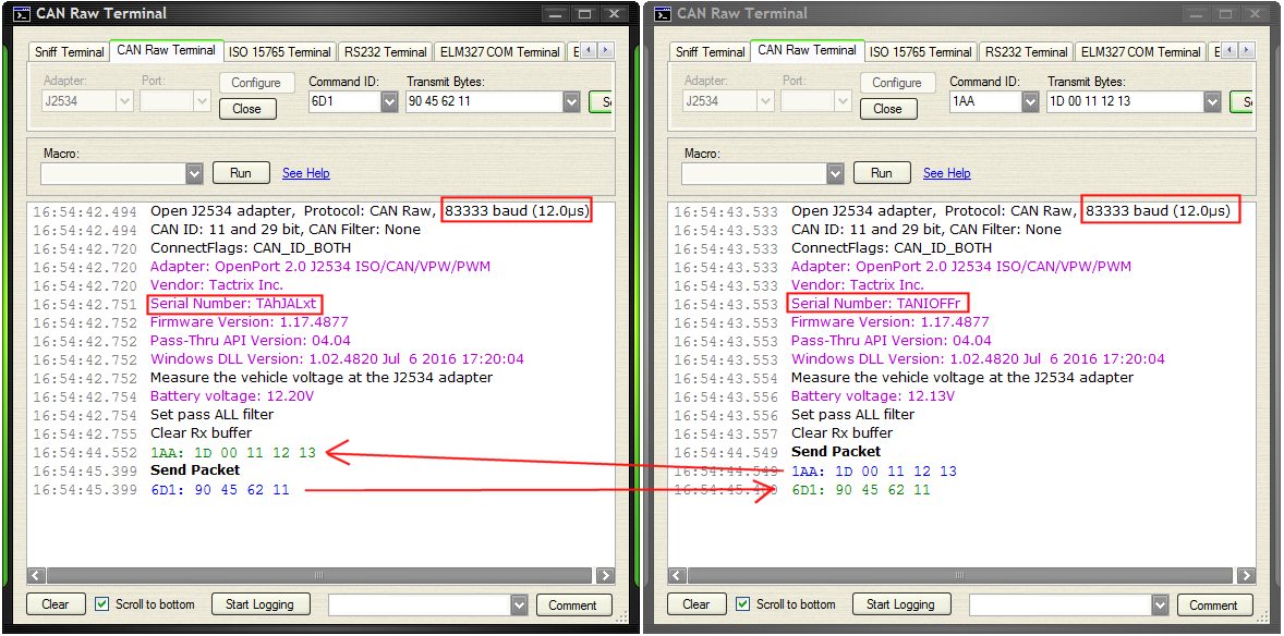
CAN Raw Terminal
Adapter: J2534
Port:
Configure
Close
Command ID: 6D1
Transmit Bytes: 90 45 62 11
Macro:
Run
See Help
Open J2534 adapter, Protocol: CAN Raw, 83333 baud (12.0µs)
CAN ID: 11 and 29 bit, CAN
. MAX. UNIT Protection paths Number of lines which can be protected N - - 2 lines channel Reverse stand-off voltage Max. reverse working voltage VRWM - - 5 V Reverse voltage at R = 10 μA VR 5 - - V Reverse current at VR= 5 V IR - - 10 μA Reverse breakdown
16949 certifi ed facilities), please refer to the related automotive grade (Q-suffix) part. A listing can be found at https://www.diodes.com/products/automotive/automotive- products/. • This part is qualified to JEDEC standards (as references in AEC-Q) for High Reliability. https://www.diodes.com/quality

 Bild