-
Datei
eeprom_24c04.asm
auslesen TEST, nach sprut.de loops equ 0x20 loops2 equ 0x21 Datenpuffer equ 0x22 ; einstellen von RC3 & RC4 auf input bsf STATUS, RP0 ; Bank 1 movlw B'00011000' ; RC3,4 inputs iorwf TRISC, f ; + RC2=CCP1 output movlw B'00000000' movwf TRISB ; PORTB als Ausgang bcf STATUS, RP0 ; Bank 0 ; einstellen des
in „EEPROM 24C04“ · Mikrocontroller und Digitale Elektronik ·
-
PDF
PIC16F8X_JP.pdf
ööľľľõĴİĪĹĶĪįİķõĪĶĴ ͔ΒೖखͰ͖·͢ ð PIC16F8X දçøúôùɿ ඪ४తͳçęĊçΦγϨʔλपçĝĚçĝ ɺĊČğěçĄçù÷çķčç ċċ ċĐėçύοέʔδͰଌఆɺěçĄçùü ˆ 5.5 5.0 R = 5k 4.5 4.0 3.5 z H R = 10k (3.0 s F 2.5 2.0 1.5 1.0 0.5 R = 100k 0.0 2.0 2.5 3.0 3.5 4.0 4.5 5.0 5.5 6.0 V DD (Volts) ن֨ʹ͍ͭͯ࠷৽൛σʔλγʔτ ï ӳޠ ð Λࢀর͍ͯͩ͘͠͞ɻ DS30430C-J2-page 98 1998 Microchip
in „Denglisch sprechender Kollege“ · Ausbildung, Studium & Beruf ·
-
Datei
2k_v4_8_switch.txt
Schaltimpuls gewertet und dabei entweder als "lang" oder "kurz" gewertet. Voreingestellt ist hier 500 ms = 0,5 Sekunden, was eine vernünftige Schaltfrequenz sein dürfte. Beispiel: - Schalter vom RC Sender auf 100 % für eine kurze Zeit von 0,35 s schaltet Ausgang 1 - Schalter vom RC Sender auf -100 % für eine
in „2 Kanal RC-Schalter fuer Schiffsmodelle mit Mega8“ · Projekte & Code ·
-
Datei
2k_v4_8_switch.cc
Schaltimpuls gewertet und dabei entweder als "lang" oder "kurz" gewertet. Voreingestellt ist hier 500 ms = 0,5 Sekunden, was eine vernünftige Schaltfrequenz sein dürfte. Beispiel: - Schalter vom RC Sender auf 100 % für eine kurze Zeit von 0,35 s schaltet Ausgang 1 - Schalter vom RC Sender auf -100 % für eine
in „2 Kanal RC-Schalter fuer Schiffsmodelle mit Mega8“ · Projekte & Code ·
-
Datei
2k_v4_8_switch.cpp
Schaltimpuls gewertet und dabei entweder als "lang" oder "kurz" gewertet. Voreingestellt ist hier 500 ms = 0,5 Sekunden, was eine vernünftige Schaltfrequenz sein dürfte. Beispiel: - Schalter vom RC Sender auf 100 % für eine kurze Zeit von 0,35 s schaltet Ausgang 1 - Schalter vom RC Sender auf -100 % für eine
in „2 Kanal RC-Schalter fuer Schiffsmodelle mit Mega8“ · Projekte & Code ·
-
Datei
2k_v4_8_switch.c
Schaltimpuls gewertet und dabei entweder als "lang" oder "kurz" gewertet. Voreingestellt ist hier 500 ms = 0,5 Sekunden, was eine vernünftige Schaltfrequenz sein dürfte. Beispiel: - Schalter vom RC Sender auf 100 % für eine kurze Zeit von 0,35 s schaltet Ausgang 1 - Schalter vom RC Sender auf -100 % für eine
in „2 Kanal RC-Schalter fuer Schiffsmodelle mit Mega8“ · Projekte & Code ·
-
Datei
2k_v4_8_switch.c
Schaltimpuls gewertet und dabei entweder als "lang" oder "kurz" gewertet. Voreingestellt ist hier 500 ms = 0,5 Sekunden, was eine vernünftige Schaltfrequenz sein dürfte. Beispiel: - Schalter vom RC Sender auf 100 % für eine kurze Zeit von 0,35 s schaltet Ausgang 1 - Schalter vom RC Sender auf -100 % für eine
in „2 Kanal 8 fach Switch RC für Modell Schiff und Auto“ · Projekte & Code ·
-
Datei
2k_v4_8_switch.c
Schaltimpuls gewertet und dabei entweder als "lang" oder "kurz" gewertet. Voreingestellt ist hier 500 ms = 0,5 Sekunden, was eine vernünftige Schaltfrequenz sein dürfte. Beispiel: - Schalter vom RC Sender auf 100 % für eine kurze Zeit von 0,35 s schaltet Ausgang 1 - Schalter vom RC Sender auf -100 % für eine
in „2 Kanal 8 fach Switch RC für Modell Schiff und Auto“ · Mikrocontroller und Digitale Elektronik ·
-
PDF
HF_Attenuator_Package_v1.pdf
R123 C106 C103 95.3 95.3 60.4 60.4 R108 100p 100p 1n 10 dB 20 dB R122a R122b 10k 7 60.4 40 dB 60.4 +5V(JP2) +5V(JP1) C117 0.1u FB110 +5V +5V(JP1) +5V(JP2) C114 P130 1 +12v X I U150 O 0.1u 14 G + C131 C130 C118 U110 C112 0.1u 10u 1u 100p C110 GND X 2,5 R115 1,3,5 R113 1n 1k 2,4,6 24.9 1 C115 R117 100p
in „Bistabiles Relais ansteuern“ · Mikrocontroller und Digitale Elektronik ·
-
PDF
HF_Attenuator_Package_v1.pdf
R123 C106 C103 95.3 95.3 60.4 60.4 R108 100p 100p 1n 10 dB 20 dB R122a R122b 10k 7 60.4 40 dB 60.4 +5V(JP2) +5V(JP1) C117 0.1u FB110 +5V +5V(JP1) +5V(JP2) C114 P130 1 +12v X I U150 O 0.1u 14 G + C131 C130 C118 U110 C112 0.1u 10u 1u 100p C110 GND X 2,5 R115 1,3,5 R113 1n 1k 2,4,6 24.9 1 C115 R117 100p
in „bistabiles Relais für AVR/Arduino“ · Mikrocontroller und Digitale Elektronik ·
-
Datei
gaakgaak.bas
statischer Ausgang langer Impuls 'Pin 3: PB4, statischer Ausgang kurzer Impuls 'Pin 4: GND, Masse 'Pin 5: PB0, Steuerausgang 1 für Sound (kurz->lang-Wechsel) 'Pin 6: PB1, Impulseingang vom RC-Empfänger (über Schutzwiderstand 1k) 'Pin 7: PB2, Steuerausgang 2 für Sound (lang->kurz-Wechsel) 'Pin 8: VCC, Versorgungsspannung
in „Status abfragen, bevor es ins Hauptprogramm geht / BASCOM“ · Mikrocontroller und Digitale Elektronik ·
-
Datei
gaakgaak.bas
statischer Ausgang langer Impuls 'Pin 3: PB4, statischer Ausgang kurzer Impuls 'Pin 4: GND, Masse 'Pin 5: PB0, Steuerausgang 1 für Sound (kurz->lang-Wechsel) 'Pin 6: PB1, Impulseingang vom RC-Empfänger (über Schutzwiderstand 1k) 'Pin 7: PB2, Steuerausgang 2 für Sound (lang->kurz-Wechsel) 'Pin 8: VCC, Versorgungsspannung
in „Ich verstehe den Timer0 beim ATtiny 13 nicht.“ · Mikrocontroller und Digitale Elektronik ·
-
Datei
gaakgaak.bas
statischer Ausgang langer Impuls 'Pin 3: PB4, statischer Ausgang kurzer Impuls 'Pin 4: GND, Masse 'Pin 5: PB0, Steuerausgang 1 für Sound (kurz->lang-Wechsel) 'Pin 6: PB1, Impulseingang vom RC-Empfänger (über Schutzwiderstand 1k) 'Pin 7: PB2, Steuerausgang 2 für Sound (lang->kurz-Wechsel) 'Pin 8: VCC, Versorgungsspannung
in „RC Kanal auslesen“ · Mikrocontroller und Digitale Elektronik ·
-
Datei
gaakgaak.bas
statischer Ausgang langer Impuls 'Pin 3: PB4, statischer Ausgang kurzer Impuls 'Pin 4: GND, Masse 'Pin 5: PB0, Steuerausgang 1 für Sound (kurz->lang-Wechsel) 'Pin 6: PB1, Impulseingang vom RC-Empfänger (über Schutzwiderstand 1k) 'Pin 7: PB2, Steuerausgang 2 für Sound (lang->kurz-Wechsel) 'Pin 8: VCC, Versorgungsspannung
in „RC-Empfänger auslesen“ · Mikrocontroller und Digitale Elektronik ·
-
Datei
BUS-Netzteil.c
1.2 * Created: 20.11.2017 * * ************************************* * OSC: 10MHz Crystal * * UART: RC6= TX * RC7= RX * * Output: RA1= Rail0 * RB1= Rail1 * RC4= LED Rail 0 * RC3= LED Rail 1 * * Analog: RA2= Betriebsspannung 0 * RA3= Ausgangsspannung 0 * RA0= Ausgangsstrom 0 * RB2= Betriebsspannung 1 *
in „Endlosschleife bei Division - Interrupt Trap!“ · Mikrocontroller und Digitale Elektronik ·
-
Datei
main.c
// FUSEBYTE1 = 0x00 (valid) // FUSEBYTE2 = 0xFF (valid) // FUSEBYTE4 = 0xF2 (modified) // FUSEBYTE5 = 0xF1 (modifie FUSES = { .FUSEBYTE0 = FUSE0_DEFAULT, .FUSEBYTE1 = FUSE1_DEFAULT, .FUSEBYTE2 = FUSE2_DEFAULT, //.byte[3] = FUSE3_DEFAULT, // Byte 3 reserviert .FUSEBYTE4 = 0xF2, .FUSEBYTE5 = 0xF1 };
in „OLED Module Waveshare 1.3 inch“ · Mikrocontroller und Digitale Elektronik ·
-
 Bild
Bild
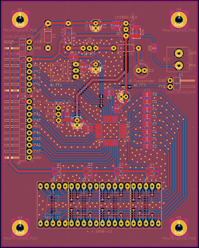
PCB-Layout einer Leiterplatte
H1 GND MountingHole_Pad D1 LP2950-3.0 H4 GND MountingHole_Pad Conn_01x02_Pin 0.5V Q1 10uF D2 GND Conn_01x02_Pin IR Receiver IR Transmitter GND PF0 PF1 470 RC RC RC
in „Entwurf USB-UART-Converter, KiCad, bitte um Review“ · Platinen · · Layouts
-
PDF
Alliance_-_as7c34098a_v2.1-1.pdf
data access, low power, and simple interfacing are desired. Equal address access and cycle times (tAA RC WC t ) of 10/12/15/20 ns with output enable access times (OE ) of 4/5/6/7 ns are ideal for high-performance applications. The chip enable input CE permits easy memory expansion with multiple-bank memory
in „Suche 3,3V SRAM mind 64kb“ · Markt ·
-
PDF
EZ_K5.pdf
= i(t) · R + y(t) i(t) R i(t) x(t)=u (t) C e y(t)=u at) Bild 5.1.3: RC-Glied Für die Kapazität C gilt: 7 i( )= C* y ( ( ) Wir setzen in die Widerstandsgleichung ein und erhalten: x ( ) R*C* y ( ( ) y ( ) Wir teilen durch R*C: ( ) 1 1 y ( )+ * y( )= *x ( ) R C R
in „Regler in Assembler?“ · Mikrocontroller und Digitale Elektronik ·
-
PDF
STM32F107.pdf
Sleep mode 36 MHz 14.5 3 24 MHz 9.8 2 16 MHz 6.6 1.4 Running on high speed internal RC 8 MHz 3.3 0.7 (HSI),AHBprescaler 4 MHz 2 0.6 used to reduce the frequency 2 MHz 1.25 0.55 1 MHz 0.9 0.5 500 kHz 0.7 0.45 125 kHz 0.6 0.45
in „STM32-comStick USB-Bootloader“ · Mikrocontroller und Digitale Elektronik ·
-
Datei
irmp.h
undef IRMP_SUPPORT_RUWIDO_PROTOCOL # define IRMP_SUPPORT_RUWIDO_PROTOCOL 0 #endif #if IRMP_SUPPORT_RC6_PROTOCOL == 1 && IRMP_SUPPORT_ROOMBA_PROTOCOL == 1 # warning RC6 protocol conflicts wih ROOMBA, please enable only one of both protocols # warning ROOMBA protocol disabled # undef IRMP_SUPPORT_ROOMBA_PROTOCOL # define IRMP_SUPPORT_ROOMBA_PROTOCOL 0 #endif #if IRMP_SUPPORT_RC5_PROTOCOL == 1 && IRMP_SUPPORT_ORTEK_PROTOCOL == 1 # warning RC5 protocol conflicts wih ORTEK, please enable only one of both protocols # warning ORTEK protocol disabled # undef IRMP_SUPPORT_ORTEK_PROTOCOL
in „IRMP - Infrared Multi Protocol Decoder“ · Projekte & Code ·
-
PDF
DOC0942.pdf
only three port pins are used. A schematic diagram is found in Figure 1. Figure 1. Circuit Diagram 5V RESET VCC PD0 PB7(SCK) PD1 PB6(MISOI) XTAL2 PB5(MOSI) XTAL1 PB4 PD2(INT0) PB3 R PD3 PB2 PD4(T0) PB1(AIN1) UIN PD5 PB0(AIN0) GND PD6 AT90S1200 Rev. 0942B–AVR–05/02 C 1 The time constant of the R/C network must be tuned so that the following equation is satisfied: 512 ▯ 2▯ 1002 -------RC l▯1 – -▯ ▯ RC = ------------ f 5 f Component values for some typical Oscillator frequencies are shown in Table 1. If the time constant varies from this, it will cause errors in the result. This makes
in „ADC: Messung einer analogen Spannung“ · Analoge Elektronik und Schaltungstechnik ·
-
Datei
model_MJE2955_MJE3055.txt
MJE2955 PNP(Is=66.19f Xti=3 Eg=1.11 Vaf=100 Bf=137.6 Ise=862.2f + Ne=1.481 Ikf=1.642 Nk=.5695 Xtb=2 Br=5.88 Isc=273.5f Nc=1.24 + Ikr=3.555 Rc=79.39m Cjc=870.4p Mjc=.6481 Vjc=.75 Fc=.5 + Cje=390.1p Mje=.4343 Vje=.75 Tr=235.4n Tf=23.21n Itf=71.33 + Xtf=5.982 Vtf=10 Rb=.1) .MODEL MJE3055 NPN(Is=457.5f Xti=
in „LTSpice Simulation.Parameter?“ · Analoge Elektronik und Schaltungstechnik ·
-
PDF
_AM_Mittelwellen-Pruefsender.pdf
7.049f Xti=3 Eg=1.11 Vaf=59.93 Bf=375.6 Ise=56.03f 33k 4.7k 1k + Ne=1.553 Ikf=87.07mNk=.4901 Xtb=1.5 Br=2.886 Isc=7.371p + Nc=1.508 Ikr=5.426 Rc=1.175 Cjc=5.5pMjc=.3132 Vjc=.4924 Fc=.5 + Cje=11.5pMje=.6558 Vje=.5 Tr=10n Tf=417.3pItf=1.512 Xtf=39.51 + Vtf=10) C4 Q1 V1 * PHILIPS pid=bc549b case=TO92 1n BC550C * 91-07-31 dsq C2 12 *$ R5 .model BC550C NPN(Is=7.049f Xti=3 Eg=1.11 Vaf=23.89 Bf=493.2 Ise=99.2f 5 1n + Ne=1.829 Ikf=.1542 Nk=.6339 Xtb=1.5 Br=2.886 Isc=7.371p Q2 + Nc=1.508 Ikr=5.426 Rc=1.175 Cjc=5.5pMjc=.3132 Vjc=.4924 Fc=.5
in „AM Mittelwellensender Prüfsender“ · HF, Funk und Felder ·
-
PDF
doc4779atr2406.pdf
bits D24 D23 D22 D21 D20 D19 D18 D17 D16 1 0 1 0 0 0 0 0 0 LSB D15 D14 D13 D12 D11 D10 D9 D8 D7 D6 D5 D4 D3 D2 D1 D0 0 0 X X X X X 0 RC MC SC Note: X values are not relevant and can be set to 0 or 1. 7.5 PLL Settings RC, MC and SC bits are controlling the synthesizer frequency according to Table 7-3,
in „Gauss Anpassung Register“ · Mikrocontroller und Digitale Elektronik ·
-
Datei
frq_intrc.asm
//www.sprut.de/electronic/pic/projekte/frequenz/freq.htm ; ; angepasst für PIC16F628a mit internen RC-Takt und ; Messung ohne Vorteiler ; ; Prozessor-Takt ca. 4 MHz (interner RC) ; ; Messbereich bei Messdauer 1/4 sek ca. ; 20 Hz ... 500kHz ; ;**********************************************************
in „Frequenzzähler 1Hz-100khZ“ · Mikrocontroller und Digitale Elektronik ·
-
Datei
fremd.bas
*************************************** 'Kabel-Zuordnung 'RS = grün(1)/EN= gelb(2)/DB4=orange(3)/DB5=rot(4)/DB6=braun(5)/DB7=schwarz(6) ' Config Lcd = 16 * 2 Config Lcdbus = 4 Config Lcdpin = Pin , Db4 = Porta.5 , Db5 = Porta.7 , Db6 = Portc.1 , Db7 = Portc.3 , E = Porta.3 , Rs = Porta.1 'Config Lcdpin = Pin , E = Portd.1 , Rs = Portd.3 , Db7 = Portd.7 , Db6 = Portd.6 , 'Config Lcdpin = Pin , Db5 = Portd.5 , Db4 = Portd.4 'Config Lcd = 16 * 2 'Config Rc5 = Pinc.4 Config Rc5 = Pind.4 'Config Portc.0 = output Config Portb.0 = Output 'Portc.4 = 1 '???????????????????????????? Portd.4 = 1 Initlcd
in „Mal wieder RC5 und Bascom“ · Mikrocontroller und Digitale Elektronik ·
-
PDF
AVR400.pdf
only three port pins are used. A schematic diagram is found in Figure 1. Figure 1. Circuit Diagram 5V RESET VCC PD0 PB7(SCK) PD1 PB6(MISOI) XTAL2 PB5(MOSI) XTAL1 PB4 PD2(INT0) PB3 PD3 PB2 R PD4(T0) PB1(AIN1) UIN PD5 PB0(AIN0) GND PD6 AT90S1200 C Rev. 0942B–AVR–05/02 1 The time constant of the R/C network must be tuned so that the following equation is satisfied: --------RC ln1 – --⇒ RC = ----------- f 5 f Component values for some typical Oscillator frequencies are shown in Table 1. If the time constant varies from this, it will cause errors in the result. This makes
in „AT90S2313 und die Beleuchtung messen“ · Mikrocontroller und Digitale Elektronik ·
-
Datei
LCD_library_selber_geschrieben.c
stdlib.h> //Umwandlung von Zahlen in einen String char wert[7]; void Clock_init(void) { OSC.CTRL |= OSC_RC32MEN_bm; //aktiviert den internen 32MHz Oszillator. while(!(OSC.STATUS & OSC_RC32MRDY_bm)); //wartet bis Oszlliator stabil CCP = CCP_IOREG_gc; //dient dazu um die I/O Register zu schützen CLK.CTRL = CLK_SCLKSEL_RC32M_gc; //Taktquelle 32MHz Oszillator } int main(void) { Clock_init(); init_lcd(); lcd_string("Zeile 1 "); lcd_string(dtostrf(55.3,5,2,wert)); //Gibt eine Zahl aus lcd_cursor_position(20); lcd_string(
in „Suche Bibliothek / Library: LCD für ATXMEGA“ · Platinen ·
-
PDF
Texas-Instruments-LMV324IPWR.pdf
to 125 (RC1F, RC1K) & no Sb/Br) LMV321IDBVRG4 ACTIVE SOT-23 DBV 5 3000 Green (RoHS CU NIPDAU Level-1-260C-UNLIM -40 to 125 (RC1F, RC1K) & no Sb/Br) LMV321IDBVT ACTIVE SOT-23 DBV 5 250 Green (RoHS CU NIPDAU Level-1-260C-UNLIM -40 to 125 (RC1F, RC1K) & no Sb/Br) LMV321IDBVTE4 ACTIVE SOT-23 DBV 5 250 Green (RoHS CU NIPDAU Level-1-260C-UNLIM -40 to 125 (RC1F, RC1K) & no Sb/Br) LMV321IDCKR ACTIVE SC70 DCK 5 3000 Green (RoHS CU NIPDAU | Level
in „Poti / Buffer / ADC / STM32“ · Mikrocontroller und Digitale Elektronik ·
-
PDF
Texas-Instruments-LMV324I.pdf
to 125 (RC1F, RC1K) & no Sb/Br) LMV321IDBVRG4 ACTIVE SOT-23 DBV 5 3000 Green (RoHS CU NIPDAU Level-1-260C-UNLIM -40 to 125 (RC1F, RC1K) & no Sb/Br) LMV321IDBVT ACTIVE SOT-23 DBV 5 250 Green (RoHS CU NIPDAU Level-1-260C-UNLIM -40 to 125 (RC1F, RC1K) & no Sb/Br) LMV321IDBVTE4 ACTIVE SOT-23 DBV 5 250 Green (RoHS CU NIPDAU Level-1-260C-UNLIM -40 to 125 (RC1F, RC1K) & no Sb/Br) LMV321IDCKR ACTIVE SC70 DCK 5 3000 Green (RoHS CU NIPDAU | Level
in „LMV324 frage zu 0-5v->0-3.3V“ · Analoge Elektronik und Schaltungstechnik ·
-
Datei
RGBLEDFlex.bas
Config Portc.7 = Output 'Ir-RC5 Config Rc5 = Ir , Timer = 0 , Wait = 6000 Irport = 1 'Pwm Config Timer1 = Pwm , Pwm = 8 , Compare A Pwm = Clear Up , Compare B Pwm = Clear Up , Prescale = 1 Config Timer2 = Pwm , Compare Pwm = Clear
in „RGB Flexband mit gemeinsamer Kathode und PWM“ · Mikrocontroller und Digitale Elektronik ·
-
Datei
test.c
< WF_SAMPLE_CNT; i++) { data12[i] = ( ( sin( (2.0 / (float) WF_SAMPLE_CNT) * (float) i * M_PI) * 0.5 + 0.5 ) * 0xFFF ); } } int main() { // // Clock // // Internen 32Mhz Oszillator einschalten OSC.CTRL = OSC_RC32MEN_bm; // Warten bis Oszillator stabil ist while ((OSC.STATUS & OSC_RC32MRDY_bm) == 0);
in „Xmega Soundcheck“ · Mikrocontroller und Digitale Elektronik ·
-
PDF
ImprovingNoiseImmunityforSerialInterface.pdf
have built-in noise filter for the serial interface. Techniques to improve noise immunity External RC Filter Adding an external RC low-pass filter on the serial interface pins is one way of implementing a noise filter. However, a simple RC filter with time constant of 50 ns also slows the rising edges
in „Signalqualität I²C“ · Digitale Signalverarbeitung / DSP / Machine Learning ·
-
Datei
2k_v4_8_switch.txt
Schaltimpuls gewertet und dabei entweder als "lang" oder "kurz" gewertet. Voreingestellt ist hier 500 ms = 0,5 Sekunden, was eine vernünftige Schaltfrequenz sein dürfte. Beispiel: - Schalter vom RC Sender auf 100 % für eine kurze Zeit von 0,35 s schaltet Ausgang 1 - Schalter vom RC Sender auf -100 % für eine
in „2 Kanal 8 fach Switch RC für Modell Schiff und Auto“ · Projekte & Code ·
-
Datei
2k_v4_8_switch.txt
Schaltimpuls gewertet und dabei entweder als "lang" oder "kurz" gewertet. Voreingestellt ist hier 500 ms = 0,5 Sekunden, was eine vernünftige Schaltfrequenz sein dürfte. Beispiel: - Schalter vom RC Sender auf 100 % für eine kurze Zeit von 0,35 s schaltet Ausgang 1 - Schalter vom RC Sender auf -100 % für eine
in „2 Kanal 8 fach Switch RC für Modell Schiff und Auto“ · Mikrocontroller und Digitale Elektronik ·
-
 Bild
Bild
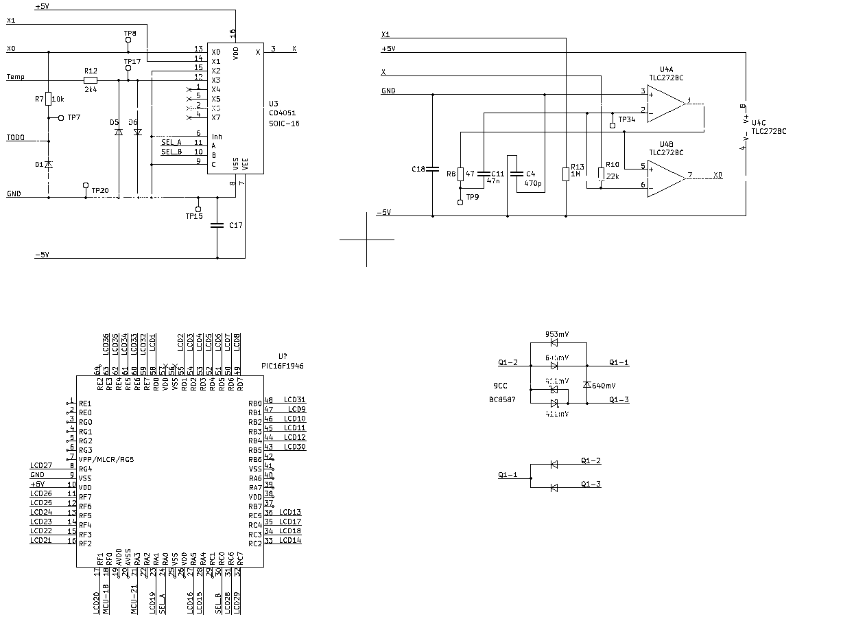
Schaltplan mit Operationsverstärkern und Mikrocontroller-Anschlüssen
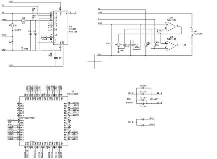
X1, +5V, TP8, X0, R12, Temp, 2k4, X2, X3, X, U3 CD4051 SOIC-16, VDD, VEE, -5V, X5, X6, X7, SEL A, SEL B, Inh, A, B, C, D1, TODO, TP7, TP20, GND, TP15, C17, U4A TLC272BC, TP34, U4C TLC272BC, X0, R16, 22k, U4B TLC272BC, C18, R6, C11, 47n, C14, 470p, TP9, U7 PIC16F1946, LCD27 bis LCD14, VPP/MCLR/RG5, VSS, +5V, LCD26, LCD25, LCD24, LCD23, LCD22, LCD21, RF1 bis RF7, MCLR/RA5, RB0 bis RB7, VDD, VSS, RA0 bis RA7, RC0 bis RC7, LCD31 bis LCD14, SEL A, SEL B, 953mV, 9CC, 451mV, 640mV, BC5487, 412mV, Q1
in „Ersa RDS 80 - Defekte Bauteile (Schaltplan benötigt)“ · Mikrocontroller und Digitale Elektronik · · Schaltpläne
-
Datei
main.c
cyan 0x7FFF #define brown 0xBC40 int main(void) { // initOSC(); //Takteinstellung OSC.CTRL |= OSC_RC32MEN_bm; while(!(OSC.STATUS & OSC_RC32MRDY_bm)); CCP = CCP_IOREG_gc; CLK.CTRL = CLK_SCLKSEL_RC32M_gc; //Port Deklarieriung PORTF.DIR = 0b11111111; //Deklarierung der Ausgänge PF0-PF7 (Datenbyte) PORTC.DIR = 0b00011111; //Deklarierung der Ausgänge PC0-PC4 für RST(Bit 0),CS,RS,WR,RD (Bit 5) initLCD(); while (1) { writecolor(yellow); } }
in „Atxmega Takteinstellung nicht mehr möglich“ · Mikrocontroller und Digitale Elektronik ·
-
PDF
NVT2001_NVT2002.pdf
) Note that the enable time and the disable time are essentially controlled by the RC time constant of the capacitor and the 200 k resistor on the EN pin. Fig 6. Typical application circuit (switch enable control) 1.8 V 5 V 1.5 V 1.2 V 200 kΩ 1.0 V totem pole or NVT20XX open-drain I/
in „Brauche Hilfe beim Verstehen eines Datenblatts“ · Mikrocontroller und Digitale Elektronik ·
-
 Bild
Bild
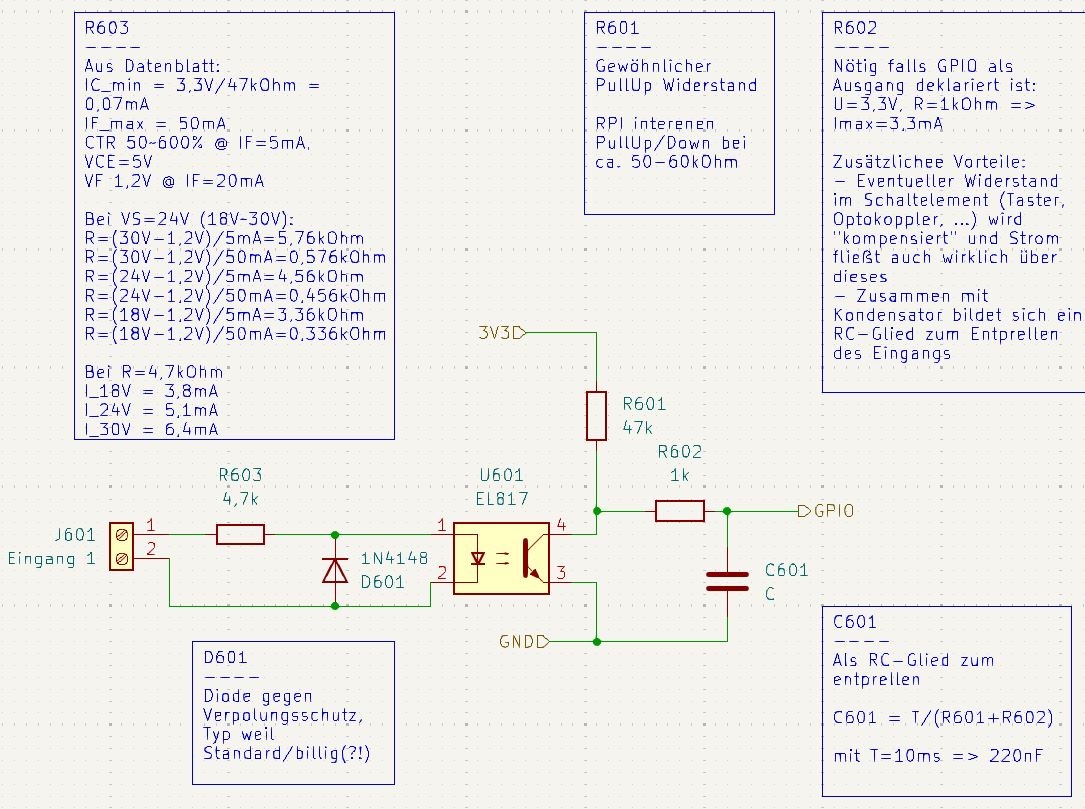
Schaltplan mit Berechnungen für Pull-up-Widerstand und RC-Glied
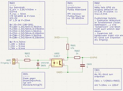
R603 Aus Datenblatt: IC_min = 3,3V/47kOhm = 0,07mA IF_max = 50mA. CTR 50-600% @ IF=5mA. VCE = 5V VF 1,2V @ IF=20mA Bei V5=24V (18V-30V): R=(30V-1,2V)/5mA=5,76kOhm R=(30V-1,2V)/50mA=0,576kOhm R=(24V-1,2V)/5mA=4,56kOhm R=(24V-1,2V)/50mA=0,456kOhm R=(18V-1,2V)/5mA=3,36kOhm R=(18V-1,2V)
in „24V Eingang an GPIO“ · Mikrocontroller und Digitale Elektronik · · Schaltpläne
-
PDF
atmel-42559-differences-between-atmega328p-and-atmega328pb_applicationnote_at15007.pdf
function ATmega328PB ATmega328 variants Full swing crystal oscillator No Yes 3.2. Calibrated Internal RC Oscillator Accuracy The accuracy for the Calibrated Internal RC Oscillator has been improved in ATmega328PB. Table 3-2. Calibration Accuracy of Internal RC Oscillator under 8MHz Frequency Test condition
in „ATmega328p: timestamp beim Flashen ohne Zusatzhardware?“ · Mikrocontroller und Digitale Elektronik ·
-
PDF
AT15007.pdf
function ATmega328PB ATmega328 variants Full swing crystal oscillator No Yes 3.2. Calibrated Internal RC Oscillator Accuracy The accuracy for the Calibrated Internal RC Oscillator has been improved in ATmega328PB. Table 3-2. Calibration Accuracy of Internal RC Oscillator under 8MHz Frequency Test condition
in „ATMega328PB lässt sich nur noch programmieren. Sonst keine Funktion mehr“ · Mikrocontroller und Digitale Elektronik ·
-
Datei
RFM_22.h
:1; unsigned char VCO_Calibr_Double_Precision:1; unsigned char RC_Calibr_Force:1; unsigned char RC_Osci_Fine_Calibr_Enable:1; unsigned char DeltaSigma_ADC_Calibr_Done:1; unsigned char Xtal_Wake_Time_Period_Halved:1; unsigned char Reserved:1; }; } _Calibration_Ctrl;
-
Datei
Test.bas
crystal = 3690000 'Taktfrequenz des STK500 'LCD Konfigurieren Config Lcdpin = Pin , Db4 = Portb.0 , Db5 = Portb.2 , Db6 = Portb.4 , Db7 = Portb.6 , E = Portb.1 , Rs = Portb.3 'LCD einstellen (ist eigendlich 8*2) Config Lcd = 16 * 2 'Cursor ausschalten Cursor Off $lib "mcsbyte.lbx" 'Eingangspinn für RC5 konfiguriren Config Rc5 = Pinb.5 'Interrupts einschalten Enable Interrupts 'Variablen definieren Dim Address As Byte , Command As Byte Dim Oldaddress As Byte , Oldcommand As Byte 'Schleife Do 'IR-Signal einlesen Getrc5(address
in „RC5 oder auch Fernbedienung“ · Mikrocontroller und Digitale Elektronik ·
-
PDF
Drehscheibe-TTL.pdf
100nF 100nF 8 4D 4Q 9 RC05 13 5D 5Q 12 17 6D 6Q 16 TO-92 TAJ-A TAJ-A TAJ-A TAJ-A 18 7D 7Q 19 8D 8Q 1 OC 11 G C S5 U1C U3A U? 9 8 1 3 74F373 20DIP300 Pos 5 10 74F86 U2B 2 74F86 S6 4 6 3 1D 1Q 2 14DIP305 74F86 14DIP300 4 2D 2Q 5 PosS7 U1D 7 3D 3Q 6 12 11 14DIP300 13 4D 4Q 12 13 74F86 14 5D 5Q 15 Pos 7 R? 17 6D 6Q 16 S8 47K 18 8D 8Q 19 D 8 7 6 5 4 3 2 1 14DIP300 1 OC Pos 8 C? C? C? C? R R R R R R R R? RC05 11 G U? 100nF 100nF
in „Mehrere Relais gleichzeitig schalten“ · Analoge Elektronik und Schaltungstechnik ·
-
Datei
LM386.lib.txt
* default parameters except Bf: .MODEL ddnpn NPN(Is=10f Xti=3 Eg=1.11 Vaf=100 + Bf=400 Ise=0 Ne=1.5 Ikf=0 Nk=.5 Xtb=1.5 Var=100 + Br=1 Isc=0 Nc=2 Ikr=0 Rc=0 Cjc=2p Mjc=.3333 + Vjc=.75 Fc=.5 Cje=5p Mje=.3333 Vje=.75 Tr=10n + Tf=1n Itf=1 Xtf=0 Vtf=10) .MODEL ddpnp PNP(Is=10f Xti=3 Eg=1.11 Vaf=100 + Bf=200 Ise=0 Ne=1.5 Ikf=0 Nk=.5 Xtb=1.5 Var=100 + Br=1 Isc=0 Nc=2 Ikr=0 Rc=0 Cjc=2p Mjc=.3333 + Vjc=.75 Fc=.5 Cje=5p Mje=.3333 Vje=.75 Tr=10n + Tf=1n Itf=1 Xtf=0 Vtf=10) .ENDS
in „PSPICE LM386“ · Analoge Elektronik und Schaltungstechnik ·
-
PDF
MOC3083M-D.pdf
Tube MOC3081SR2M SMT 6−Pin (Lead Bend) 1000 Units / Tape & Reel MOC3081VM DIP 6−Pin, DIN EN/IEC60747−5−5 Option 50 Units / Tube MOC3081SVM SMT 6−Pin (Lead Bend), DIN EN/IEC60747−5−5 Option 50 Units / Tube MOC3081SR2VM SMT 6−Pin (Lead Bend), DIN EN/IEC60747−5−5 Option 1000 Units / Tape & Reel MOC3081TVM
in „Alte Triacschaltung umbauen“ · Mikrocontroller und Digitale Elektronik ·
-
PDF
RC.pdf
Within ±10% of initial value tanδ Less than specified value ● DRAWING See page 56 ) -Series code of RC is “F” ● DIMENSIONS & MAXIMUM PERMISSIBLE RIPPLE CURRENT μF WV 6.3 10 16 25 35 50 1.0 4×5.3 7 2.2 4×5.3 11 3.3 4×5.3 13 4.7 4×5.3 13 4×5.3 14 5×5.3 18 10 4×5.3 17 5×5.3 23 5×5.3 24 6.3×5.3 31 22 4×5.3 22 5×5.3 27 5×5.3 30 6.3×5.3 39 6.3×5.3 42 6.3×5.8 45 33 5×5.3 31 5×5.3 33 6.3×5.3 43 6.3×5.3 48 6.3×5.8 52 6.3×7.7 60 47 5×5.3 36 6.3×5.3 46 6.3×5.3 51 6.3×5.8 59 6.3×5.8 63 6.3×7.7 63 100 6.3×5.3 50 6.3
in „Bauteil-Identifizierung (SMD-Elko)“ · Analoge Elektronik und Schaltungstechnik ·
-
PDF
pyroelectronics.pdf
the amplified signal, we below - in combination with a off noise signals outside the operating use RC coupling into the second stage, multisegment optical system. frequencies. What is the total whichalsoprovidesthefrequency char- amplification we would suggest to acteristic. Type Kind Application include
in „Bewegungsmelder, kostengünstig, mobil“ · Mikrocontroller und Digitale Elektronik ·
-
PDF
pyroelectronics.pdf
the amplified signal, we below - in combination with a off noise signals outside the operating use RC coupling into the second stage, multisegment optical system. frequencies. What is the total whichalsoprovidesthefrequency char- amplification we would suggest to acteristic. Type Kind Application include
in „PIR Sensor an AVR“ · Mikrocontroller und Digitale Elektronik ·