-
PDF
Schaltplan.pdf
BlCtrl_V0_3_2 05.05.2020 13:56 Sheet: 1/4 1 2 3 4 5 6 7 8 1 2 3 4 5 6 GND A IC7 A 3 3 3 2 2 2 2 2 STM32F051K8T6 _ T B B B B B 1 S O P P P P P A V O P B 3V3_STM/1.7D 1 VDD_1 PA14 24 BLHELI_TLM_RX/3.4B 2 PF0/OSC_IN PA13 23 SWDIO 3 22 4 PF1/OSC_OUT PA12 21 NRST 5 NRST PA11 20 3V3_STM/1.7D VDDA PA10 H3_
in „SD Karte/SPI Problem ab 200A -> Störungen?“ · Mikrocontroller und Digitale Elektronik ·
-
Datei
disco.txt
bits_Wide_bus PC8.Signal=SDIO_D0 PC9.Mode=SD_4_bits_Wide_bus PC9.Signal=SDIO_D1 PCC.Checker=false PCC.Line=STM32F429/439 PCC.MCU=STM32F429Z(E-G-I)Tx PCC.PartNumber=STM32F429ZITx PCC.Seq0=0 PCC.Series=STM32F4 PCC.Temperature=25 PCC.Vdd=null PD0.GPIOParameters=GPIO_Speed,GPIO_PuPd,GPIO_Speed_High_Default,GPIO_Mode
in „FMC auf STM32F4 konfigurieren?“ · Mikrocontroller und Digitale Elektronik ·
-
PDF
STM32F746-DISCO-OSCI.pdf
STM32F746G-DISCO-OSCI – recording into “Wave file” on SD-Card STM32F746G-DISCO-OSCI – only an “Estimation-Iron” (free translation from “Schätzeisen” ;-) or maybe a little bit more? The intention for this project: - Getting in touch with the STM32F7xx device family - Evaluation of STemWIN for GUI development So I bought my first “STM32F746G-DISCO”... ...and nothing is better for evaluation and whirl up potential problems more, than making a
in „STM32F746G-DISCO-OSCI mit WAV-Recording auf SD-Karte“ · Projekte & Code ·
-
Datei
0001-Add_Frre_Text_Support_To_STM32.patch
--------- + */ +#ifndef FREETEXT_H +#define FREETEXT_H + +#include "eeprom-data.h" + +#if defined (STM32F10X) +# include "stm32f10x.h" +#elif defined (STM32F4XX) +# include "stm32f4xx.h" +#endif + +typedef struct +{ + char free_text[EEPROM_DATA_SIZE_FREE_TEXT+1]; +} FREETEXT_GLOBALS; + +extern FREETEXT_GLOBALS
-
Datei
Scratch_MegaSample.c
#include "stm32f4xx.h" #include "system_stm32f4xx.h" #include "stm32f4xx_gpio.h" #include "stm32f4xx_rcc.h" #include "misc.h" #include "stm32f4xx_exti.h" #include "stm32f4xx_syscfg.h" #include "stm32f4xx_spi.h" #include "stm32f4xx_usart.h" #include "stm32f4xx_adc.h" #include "stm32f4xx_dma.h" #include "Scratch_MegaSample.h" void Init_USART2(){ // Enabling the Clock for the USART1 RCC_APB1PeriphClockCmd(RCC_APB1Periph_USART2
in „STM32F4 ADC/DMA Phänomene“ · Mikrocontroller und Digitale Elektronik ·
-
Datei
stm32f4x7_eth_bsp.h
/** ****************************************************************************** * @file stm32f4x7_eth_bsp.h * @author MCD Application Team * @version V1.1.0 * @date 31-July-2013 * @brief Header for stm32f4x7_eth_bsp.c file. ******************************************************************
in „STM32-E407 Ethernet / UDP“ · Mikrocontroller und Digitale Elektronik ·
-
PDF
usr_scm_stm32com-a2-1.pdf
STM32COM-A2 [1] Contents [2] Reserved [3] uC (STM32F107) [4] User-Interface/USB/ETH [5] Power Supply This document may not be passed A2 / 10.04.2009 / Ma Contents on, duplicated or its contents utilized
in „STM32-comStick USB-Bootloader“ · Mikrocontroller und Digitale Elektronik ·
-
Datei
main.c
param None * @retval None */ int main(void) { FRESULT res; /* FatFs function common result code */ uint32_t byteswritten, bytesread; /* File write/read counts */ uint8_t wtext[] = "This is STM32 working with FatFs"; /* File write buffer */ uint8_t rtext[100]; /* File read buffer */ /* STM32F107xC HAL library
in „FatFS Beispiel STM3210C-EVAL f_open Fehler“ · Mikrocontroller und Digitale Elektronik ·
-
Datei
myfirst.s
GPIOB_AFRH , GPIOB_BASE + 0x24 .equ GPIOB_BRR , GPIOB_BASE + 0x28 @ System control registers @ USART3 on STM32F4 chips: @ USART3 on STM32F1/STM32F4 chips: pp. 1018 in RM0090 (dm00031020-stm*.pdf) .equ USART3_BASE , 0x40004800 .equ USART3_SR , USART3_BASE + 0x00 .equ USART3_DR , USART3_BASE + 0x04 .equ USART3
in „Assemblerprogramm zur Ausgabe eines Zeichens auf UART3“ · Mikrocontroller und Digitale Elektronik ·
-
PDF
MCP2307_IO_Expansion_Board_User_Manual_EN.pdf
Arduino Uno STM32F407 Raspberry Pi Vcc Voltage 3.3V/5V 3.3V/5V 3.3V/5V GND Ground GND GND GND SDA I2C data line SDA PB7 SDA SCL I2C clock line SCL PB6 SCL INTA 1 Interrupt pin 3 PA0 0(WiringPi) INTB 2 Interrupt pin
in „kennt jemand sich aus mit MC23017 IO-Board“ · Mikrocontroller und Digitale Elektronik ·
-
Datei
main.c
configured, this is done through SystemInit() function which is called from startup file (startup_stm32f2xx.s) before to branch to application main. To reconfigure the default setting of SystemInit() function, refer to system_stm32f2xx.c file */ /* Initialize LEDs on STM322xG-EVAL board */ STM_EVAL_LEDInit
in „STM3220G-EVAL + Kamera OV2460“ · Mikrocontroller und Digitale Elektronik ·
-
Datei
main.c
include "usbd_desc.h" #include "usbd_cdc_vcp.h" //Library config for this project!!!!!!!!!!! #include "stm32f4xx_conf.h" /** @addtogroup STM32F4-Discovery_Demo * @{ */ /* Private typedef -----------------------------------------------------------*/ /* Private define ------------------------------------------------------------*/ // #define STM32F4_DISCOVERY /* Private macro -------------------------------------------------------------*/ /* Private variables ---------------------------------------------------------*/ #ifdef USB_OTG_HS_INTERNAL_DMA_ENABLED
in „STM32F4 - Virtual Com Port (CDC)“ · Mikrocontroller und Digitale Elektronik ·
-
Datei
test.c
if(tempRes != FR_OK) { // FatFs Format Error Error_Handler(); } else { tempRes = f_open(&MyFile, "STM32.TXT", FA_CREATE_ALWAYS | FA_WRITE); if(tempRes != FR_OK) { /* 'STM32.TXT' file Open for write Error */ Error_Handler(); } else { tempRes = f_write(&MyFile, wtext, sizeof(wtext), (void *)&byteswritten); if((byteswritten == 0) || (tempRes != FR_OK)) { /* 'STM32.TXT' file Write or EOF Error */ Error_Handler(); } else { f_close(&MyFile); tempRes = f_open(&MyFile, "STM32.TXT", FA_READ); if(tempRes != FR_OK) { /* 'STM32.TXT' file Open for read Error */ Error_Handler
in „STM32F7 FatFS mit µSD“ · Mikrocontroller und Digitale Elektronik ·
-
Datei
CANTestcase.cpp
/* * \file CANTestcase.cpp * \brief Test case to figure out why the CAN bus works on a STM32F103RBT6 (medium-density device) but not * on a STM32RET6 (high-density device). Just create an instance of CANTestcase and call the * sendTestMessageInALoop() method. */ //Inclusions #include "CANTestcase.h" #include "../../libraries/CMSIS/CM3/DeviceSupport/ST/STM32F10x/stm32f10x.h" #include "../../libraries/STM32F10x_StdPeriph_Driver/inc/stm32f10x_can.h" /** * \brief Constructor implementation. */ CANTestcase::CANTestcase(){ this->setUp(); return; }//eof /**
in „STM32F103: CAN - Bus funktioniert bei Medium-Density-, nicht aber bei High-Density device“ · Mikrocontroller und Digitale Elektronik ·
-
Datei
test.cpp
test.cpp * * Created on: 12.08.2013 * Author: Florian */ static void initClock_ext_Oszi() { if (xpcc::stm32::Clock::enableHse(xpcc::stm32::Clock::HSE_BYPASS)) { xpcc::stm32::Clock::enablePll(xpcc::stm32::Clock::PLL_HSE, 8, 336); xpcc::stm32::Clock::switchToPll(); } } MAIN_FUNCTION { initClock_ext_Oszi(); xpcc::stm32::SysTickTimer::enable(); I2C2BUS::init_I2C2(); //LSM303DLH & Motors & Supply-Monitor Bluetooth::init(); //Bluetooth Communication to PC PreciseTimer::init(); //Timer needed for Filtering & other Stuff
in „I2C-Kommunikation stoppt nach ca. 1-5 Sekunden“ · Mikrocontroller und Digitale Elektronik ·
-
Datei
stm32_ub_uart.h
//-------------------------------------------------------------- // File : stm32_ub_uart.h //-------------------------------------------------------------- //-------------------------------------------------------------- #ifndef __STM32F4_UB_UART_H #define __STM32F4_UB_UART_H
in „STM32F4 USART“ · Mikrocontroller und Digitale Elektronik ·
-
Datei
httpd_cgi_ssi.c
const char * LEDS_CGI_Handler(int iIndex, int iNumParams, char *pcParam[], char *pcValue[]) { uint32_t i=0; /* We have only one SSI handler iIndex = 0 */ if (iIndex==0) { /* All leds off */ STM_EVAL_LEDOff(LED5); STM_EVAL_LEDOff(LED6); STM_EVAL_LEDOff(LED3); STM_EVAL_LEDOff(LED4); /* Check cgi parameter
in „LWIP Webserver“ · Mikrocontroller und Digitale Elektronik ·
-
Datei
httpd_cgi_ssi.c
const char * LEDS_CGI_Handler(int iIndex, int iNumParams, char *pcParam[], char *pcValue[]) { uint32_t i=0; /* We have only one SSI handler iIndex = 0 */ if (iIndex==0) { /* All leds off */ STM_EVAL_LEDOff(LED5); STM_EVAL_LEDOff(LED6); STM_EVAL_LEDOff(LED3); STM_EVAL_LEDOff(LED4); /* Check cgi parameter
in „LWIP Webserver“ · Mikrocontroller und Digitale Elektronik ·
-
PDF
STM32F746G_Discovery.pdf
AUDIO_SDADA USB HS i OTG_HS_O rverrrent ULPI_STP DCMII i DCMI_PIXCKCK DCMI_HSYNC AUDIO_SCLCL AUDIO_SDA U_STM32F7 OSC_24M OTG_HS_OverCurrent DCMII i DCMI_SDADA DCMI_PIXCK SAI2_MCLKAKA AUDIO_SCL STM32F7.SchDoc CLOCK i OSC_24M DCMI_SCLCL DCMI_SDA SPDIF_RX0X0 SAI2_MCLKA PA[0..15] ARD_A[0..5] DCMI_SCL SAI1_SD_A0A
in „STM32F7 Discovery Board“ · Mikrocontroller und Digitale Elektronik ·
-
Datei
Quellcode.c
#include <stm32f10x_lib.h> // STM32F10x Library Definitions #include "STM32_Init.h" // STM32 Initialization #define S3 0x00002000 // PC13: S3 #define S2 0x00000001 // PA0 : S2 #define UNBOUNCE_CNT 5 // unbounce the
in „Unverständnis bei Pinauswahl ARM“ · Mikrocontroller und Digitale Elektronik ·
-
Datei
example.txt
nxp_driver (BSD-3-Clause) . /oofatfs (BSD-1-clause) . /pico-sdk (BSD-3-clause) . /re15 (BSD-3-clause) . /stm32lib (BSD-3-clause) . /tinytest (BSD-3-clause) . /tinyusb (MIT) . /uzlib (Zlib) . /logo (uses OFL-1.1) . /ports . /cc3200 . /hal (BSD-3-clause) . /simplelink (BSD-3-clause) . /FreeRTOS (GPL-2.0 with FreeRTOS exception) . /stm32 . /usbd*.c (MCD-ST Liberty SW License Agreement V2) . /stm32_it.* (MIT + BSD-3-clause) . /system_stm32*.c (MIT + BSD-3-clause) . /boards . /startup_stm32*.s (BSD-3-clause) . /*/stm32*.h (BSD-3-clause
-
 Bild
Bild
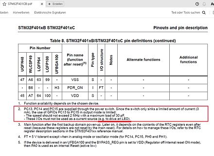
Ausschnitt einer Pin-Definitionstabelle aus einem Datenblatt
STM32F401xB STM32F401xC Pinouts and pin description Table 8. STM32F401xB/STM32F401xC pin definitions (continued) Pin Number UQFN48 WLCSP40 LQFP64 LQFP100 UFBGA100 Pin name (function after reset)(1) Pin
in „STM32 Timer2 Interrupt“ · Mikrocontroller und Digitale Elektronik · · Screenshots
-
 Bild
Bild
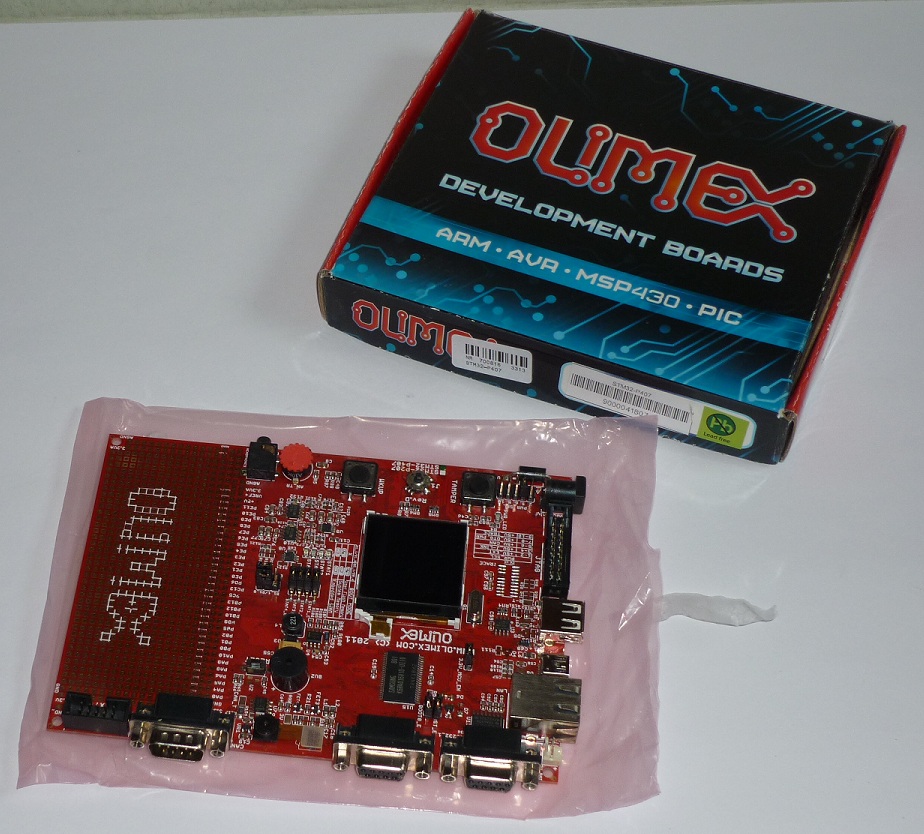
Olimex Development Board und Verpackung
OLIMEX DEVELOPMENT BOARDS ARM AVR MSP430 PIC OLIMEX www.olimex.com
in „[V] Evalboard Olimex STM32-P407“ · Markt · · Platinenfotos
-
 Bild
Bild
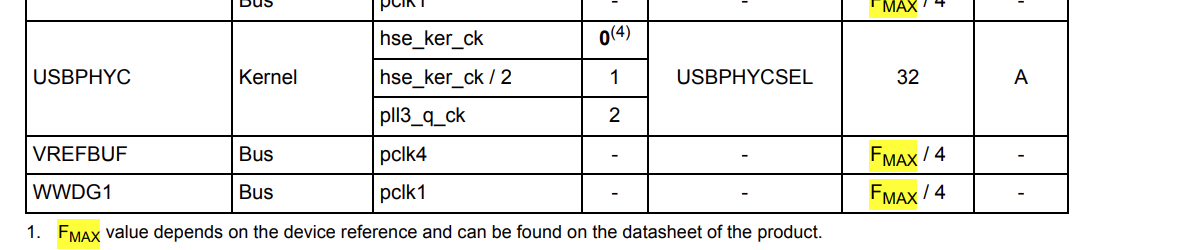
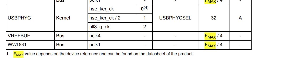
Ausschnitt einer Tabelle aus einem Datenblatt
USBPHYC Kernel hse_ker_ck 0(4) USBPHYCSEL 32 A hse_ker_ck / 2 1 pll3_q_ck 2 VREFBUF Bus pclk4 FMAX / 4 WWDG1 Bus pclk1 FMAX / 4 1. FMAX value depends on the device reference and can be found on the datasheet of the product.
in „STM32H7Sx: Maximale Frequenz?“ · Mikrocontroller und Digitale Elektronik · · Screenshots
-
Datei
STM32_SEC_FLASH.ld
/* Common part of the linker scripts for STR71x devices in FLASH mode (that is, the FLASH is seen at 0) Copyright RAISONANCE 2005 You can use, modify and distribute thisfile freely, but without any waranty. */ /* Sections Definitions */ SECTIONS { /* for Cortex devices, the beginning of the startup code is stored in the .isr_vector section, which goes to FLASH */ .isr_vector : { . = ALIGN(4); KEEP(*(.isr_vector)) /* Startup code */ . = ALIGN(4); } >FLASH /* for some STRx devices, the beginning of the startup code is stored in the .flashtext section, which goes to FLASH */ .flashtext : { . = ALIGN
in „J-Link EDU + Eclipse + STM32-H103 Board debugging problem“ · Mikrocontroller und Digitale Elektronik ·
-
Datei
main_example_stm32.c
#include "irmp.h" #include "stdlib.h" #include <stdio.h> #define F_CPU 24000000 #ifndef F_CPU #error F_CPU unkown #endif void timer2ini(void); void TIM2_IRQHandler(void){ TIM_ClearITPendingBit(TIM2, TIM_IT_Update); irmp_ISR(); // call irmp ISR } int main(void) { timer2ini(); SystemInit(); irmp_init(); // initialize irmp IRMP_DATA irmp_data; while(1){ if(irmp_get_data (&irmp_data)){ //.... } } } void timer2ini(void){ TIM_TimeBaseInitTypeDef TIM_TimeBase_InitStructure; NVIC_InitTypeDef NVIC_InitStructure; RCC_APB1PeriphClockCmd(RCC_APB1Periph_TIM2, ENABLE); //Set Timer TIM2 TIM_TimeBase_InitStructure.TIM_ClockDivision
in „IRMP - Infrared Multi Protocol Decoder“ · Projekte & Code ·
-
Datei
STM32_USART_Test.c
#include <stdio.h> #include "stm32f10x_usart.h" #include "stm32f10x_rcc.h" #include "stm32f10x_gpio.h" #include <stddef.h> #include "stm32f10x.h" // Function prototypes void InitUart1(void); void InitUart2(void); void USART1_Send(char
in „STM32 und usart1/2 Initialisierung“ · Mikrocontroller und Digitale Elektronik ·
-
Datei
STM32_USART_Test.c
#include <stdio.h> #include "stm32f10x_usart.h" #include "stm32f10x_rcc.h" #include "stm32f10x_gpio.h" #include <stddef.h> #include "stm32f10x.h" // Function prototypes void InitUart1(void); void InitUart2(void); void USART1_Send(char
in „STM32 und usart1/2 Initialisierung“ · Mikrocontroller und Digitale Elektronik ·
-
Datei
STM32_USART_Test.c
#include <stdio.h> #include "stm32f10x_usart.h" #include "stm32f10x_rcc.h" #include "stm32f10x_gpio.h" #include <stddef.h> #include "stm32f10x.h" // Function prototypes void InitUart1(void); void InitUart2(void); void USART1_SendString
in „STM32 und usart1/2 Initialisierung“ · Mikrocontroller und Digitale Elektronik ·
-
Datei
STM32_USART_Test.c
#include <stdio.h> #include "stm32f10x_usart.h" #include "stm32f10x_rcc.h" #include "stm32f10x_gpio.h" #include <stddef.h> #include "stm32f10x.h" void USART_NVIC_Config(void); // Function prototypes void InitUart1(void); void InitUart2
in „STM32 und usart1/2 Initialisierung“ · Mikrocontroller und Digitale Elektronik ·
-
Datei
STM32F4.ld
OUTPUT_FORMAT ("elf32-littlearm", "elf32-bigarm", "elf32-littlearm") /* Internal Memory Map*/ MEMORY { rom (rx) : ORIGIN = 0x08000000, LENGTH = 0x00100000 ram (rwx) : ORIGIN = 0x20000000, LENGTH = 0x00020000 ccm (rwx) : ORIGIN = 0x10000000, LENGTH = 0x00010000 } _eram = 0x20000000 + 0x00020000; SECTIONS { .text : { KEEP(*(.isr_vector)) *(.text*) *(.rodata*) } > rom __etext = .; /* _sidata is used in coide startup code */ _sidata = __etext; .data : AT (__etext) { __data_start__ = .; /* _sdata is used in coide startup code */ _sdata = __data_start__; *(vtable) *(.data*) . = ALIGN(4); /* All data end
in „GCC STM32F4 -> Wie Variablen auf RAM bereiche verteilen“ · Mikrocontroller und Digitale Elektronik ·
-
Datei
STM32F100.ld
ENTRY(_reset) MEMORY { /* memory map of STM32F100 */ Flash (rx): ORIGIN = 0x08000000, LENGTH = 256K SRAM0 (rwx): ORIGIN = 0x20000000, LENGTH = 64K } _stack_end = ORIGIN(SRAM0) + LENGTH(SRAM0); SECTIONS { .text : { _text_section_start = .; KEEP
in „uint64_t auf STM32F103“ · Mikrocontroller und Digitale Elektronik ·
-
Datei
stm32_ub_uart.c
//-------------------------------------------------------------- // File : stm32_ub_uart.c // Datum : 28.07.2015 // Version : 1.5 // Autor : UB // EMail : mc-4u(@)t-online.de // Web : www.mikrocontroller-4u.de // CPU : STM32F4 // IDE : CooCox CoIDE 1.7.8 // GCC : 4.9 2015q2 //
in „STM32F4 USART“ · Mikrocontroller und Digitale Elektronik ·
-
Datei
stm32f103.h
typedef enum {CAN_50KBPS, CAN_100KBPS, CAN_125KBPS, CAN_250KBPS, CAN_500KBPS, CAN_1000KBPS} BITRATE; #pragma once typedef enum {STANDARD_FORMAT = 0, EXTENDED_FORMAT} CAN_FORMAT; typedef enum {DATA_FRAME = 0, REMOTE_FRAME} CAN_FRAME; typedef struct { uint32_t id; /* 29 bit identifier */ uint8_t data[8]; /* Data field */ uint8_t len; /* Length of data field in bytes */ uint8_t ch; /* Object channel(Not use) */ uint8_t format; /* 0 - STANDARD, 1- EXTENDED IDENTIFIER */ uint8_t type; /* 0 - DATA FRAME, 1 - REMOTE FRAME */ } CAN_msg_t; bool CANInit(BITRATE bitrate, int remap); void CANReceive(CAN_msg_t
in „Arduino Blue Pill CAN bibliothek“ · Mikrocontroller und Digitale Elektronik ·
-
Datei
stm32_spi_eigen.c
// Programm zur initialisierung der SPI-Schnittstelle + Schreibvorgang #include "stm32_spi_eigen.h" GPIO_InitTypeDef GPIO_InitStructure; SPI_InitTypeDef SPI_InitStructure; void initNSS() { //RCC_AHBPeriphClockCmd(RCC_AHBPeriph_GPIOA,ENABLE); GPIO_InitStructure.GPIO_Pin = GPIO_Pin_6;
in „AD9833 mittels STM32F072 per SPI ansteuern“ · Mikrocontroller und Digitale Elektronik ·
-
Datei
stm32_ub_irsnd.c
//-------------------------------------------------------------- // File : stm32_ub_irsnd.c // Datum : 14.06.2013 // Version : 1.0 // Autor : UB // EMail : mc-4u(@)t-online.de // Web : www.mikrocontroller-4u.de // CPU : STM32F4 // IDE : CooCox CoIDE 1.7.0 // Module : IRSND, TIM
in „IRSND auf STM32F0“ · Mikrocontroller und Digitale Elektronik ·
-
Datei
stm32f446.c
#include <stdlib.h> #include <stdint.h> #include "stm32f4_regs.h" #include "usart.h" #include "gpio.h" #define CONFIG_HSE_HZ 16000000 #define CONFIG_PLL_M 16 #define CONFIG_PLL_N 336 #define CONFIG_PLL_P 2 #define CONFIG_PLL_Q 7 #define PLLCLK_HZ (((CONFIG_HSE_HZ
in „Linux auf dem STM32 externes RAM“ · Mikrocontroller und Digitale Elektronik ·
-
Datei
stm32_ub_uart.c
//-------------------------------------------------------------- // File : stm32_ub_uart.c // Datum : 28.11.2013 // Version : 1.3 // Autor : UB // EMail : mc-4u(@)t-online.de // Web : www.mikrocontroller-4u.de // CPU : STM32F4 // IDE : CooCox CoIDE 1.7.0 // Module : GPIO, USART
in „STM32F030F4P6 und USART1“ · Mikrocontroller und Digitale Elektronik ·
-
Datei
stm32_ub_rng.c
//-------------------------------------------------------------- // File : stm32_ub_rng.c // Datum : 23.02.2013 // Version : 1.0 // Autor : UB // EMail : mc-4u(@)t-online.de // Web : www.mikrocontroller-4u.de // CPU : STM32F4 // IDE : CooCox CoIDE 1.7.0 // Module : RNG // Funktion
in „Random Number Generator läuft nicht richtig,stm32f429“ · Mikrocontroller und Digitale Elektronik ·
-
Datei
stm32f103.h
typedef enum {CAN_50KBPS, CAN_100KBPS, CAN_125KBPS, CAN_125KBPS32MHZ, CAN_125P1KBPS31P9MHZ,CAN_250KBPS, CAN_500KBPS, CAN_1000KBPS} BITRATE; typedef enum {STANDARD_FORMAT = 0, EXTENDED_FORMAT} CAN_FORMAT; typedef enum {DATA_FRAME = 0, REMOTE_FRAME} CAN_FRAME; typedef struct { uint32_t id; /* 29 bit identifier */ uint8_t data[8]; /* Data field */ uint8_t len; /* Length of data field in bytes */ uint8_t ch; /* Object channel(Not use) */ uint8_t format; /* 0 - STANDARD, 1- EXTENDED IDENTIFIER */ uint8_t type; /* 0 - DATA FRAME, 1 - REMOTE FRAME */ } CAN_msg_t; bool CANInit(BITRATE bitrate, int remap); void
in „Arduino Blue Pill & CAN mit SN65HVD230“ · Mikrocontroller und Digitale Elektronik ·
-
Datei
stm32f103.h
#pragma once typedef enum {CAN_50KBPS, CAN_100KBPS, CAN_125KBPS, CAN_250KBPS, CAN_500KBPS, CAN_1000KBPS} BITRATE; typedef enum {STANDARD_FORMAT = 0, EXTENDED_FORMAT} CAN_FORMAT; typedef enum {DATA_FRAME = 0, REMOTE_FRAME} CAN_FRAME; typedef struct { uint32_t id; /* 29 bit identifier */ uint8_t data[8]; /* Data field */ uint8_t len; /* Length of data field in bytes */ uint8_t ch; /* Object channel(Not use) */ uint8_t format; /* 0 - STANDARD, 1- EXTENDED IDENTIFIER */ uint8_t type; /* 0 - DATA FRAME, 1 - REMOTE FRAME */ } CAN_msg_t; bool CANInit(BITRATE bitrate, int remap); void CANReceive(CAN_msg_t
in „Arduino Blue Pill & CAN mit SN65HVD230“ · Mikrocontroller und Digitale Elektronik ·
-
Datei
stm32f103.h
typedef enum {CAN_50KBPS, CAN_100KBPS, CAN_125KBPS, CAN_250KBPS, CAN_500KBPS, CAN_1000KBPS} BITRATE; #pragma once typedef enum {STANDARD_FORMAT = 0, EXTENDED_FORMAT} CAN_FORMAT; typedef enum {DATA_FRAME = 0, REMOTE_FRAME} CAN_FRAME; typedef struct { uint32_t id; /* 29 bit identifier */ uint8_t data[8]; /* Data field */ uint8_t len; /* Length of data field in bytes */ uint8_t ch; /* Object channel(Not use) */ uint8_t format; /* 0 - STANDARD, 1- EXTENDED IDENTIFIER */ uint8_t type; /* 0 - DATA FRAME, 1 - REMOTE FRAME */ } CAN_msg_t; bool CANInit(BITRATE bitrate, int remap); void CANReceive(CAN_msg_t
in „Arduino Blue Pill & CAN mit SN65HVD230“ · Mikrocontroller und Digitale Elektronik ·
-
Datei
stm32f103.h
typedef enum {CAN_50KBPS, CAN_100KBPS, CAN_125KBPS, CAN_125KBPS32MHZ, CAN_125P1KBPS31P9MHZ,CAN_250KBPS, CAN_500KBPS, CAN_1000KBPS} BITRATE; typedef enum {STANDARD_FORMAT = 0, EXTENDED_FORMAT} CAN_FORMAT; typedef enum {DATA_FRAME = 0, REMOTE_FRAME} CAN_FRAME; typedef struct { uint32_t id; /* 29 bit identifier */ uint8_t data[8]; /* Data field */ uint8_t len; /* Length of data field in bytes */ uint8_t ch; /* Object channel(Not use) */ uint8_t format; /* 0 - STANDARD, 1- EXTENDED IDENTIFIER */ uint8_t type; /* 0 - DATA FRAME, 1 - REMOTE FRAME */ } CAN_msg_t; bool CANInit(BITRATE bitrate, int remap); void
in „Arduino Blue Pill & CAN mit SN65HVD230“ · Mikrocontroller und Digitale Elektronik ·
-
PDF
STM32_DS1307.pdf
on the left side: GND, SDA, SCL, VCC (U = 3,3V). For I2C and USB communication we use a Black Pill (STM32F103C8T6) We only write and read the seven yellow timekeeper registers 0x00 up to 0x06. “When you power up the module the clock halt (CH) bit in the seconds register will be set to a 1.” That means
in „I2C STM32F103“ · Mikrocontroller und Digitale Elektronik ·
-
PDF
hy-stm32_schematic.pdf
PB12/SPI2_NSS/I2S2_WS/I2C2_SMBA/USART3_CK/TIM1_BKIN 51 PB12 1 C27 1 C28 0.1uF U3 22P 22P PL2303HX STM32F10xVxT6 PA4 1 8 3V3 2 2 PA6 2 CS VCC 7 3V3 GND 3V3 3 Q HOLD 6 PA5 所有 IO均已引出 4 W C 5 PA7 1 2 1 2 4 1 9 1 2 3 D IO GND D USB 接口 V E A C E E E B B D C B B D C A A A V N GND M25Pxx 3 P P P P P P P P P
-
PDF
stm32g4.pdf
stm32g4.pdf
in „stm32g431 st-link swclk swdio“ · Mikrocontroller und Digitale Elektronik ·
-
PDF
stm32g4.pdf
stm32g4.pdf
in „stm32g431 st-link swclk swdio“ · Mikrocontroller und Digitale Elektronik ·
-
PDF
stm32g4.pdf
stm32g4.pdf
in „stm32g431 st-link swclk swdio“ · Mikrocontroller und Digitale Elektronik ·
-
Datei
myfirst.s
clock generation register .set RCC_PLLI2SCFGR, 0x84 @ RCC I2S PLL configuration register @ USART3 on STM32F4 chips: @ USART3 on STM32F1/STM32F4 chips: pp. 1018 in RM0090 (dm00031020-stm*.pdf) .equ USART3_BASE , 0x40004800 .equ USART3_SR , USART3_BASE + 0x00 .equ USART3_DR , USART3_BASE + 0x04 .equ USART3
in „STM32CubeIDE - kann man dem gdb server einen Schalter mitgeben?“ · Mikrocontroller und Digitale Elektronik ·
-
Datei
myfirst168.s
clock generation register .set RCC_PLLI2SCFGR, 0x84 @ RCC I2S PLL configuration register @ USART3 on STM32F4 chips: @ USART3 on STM32F1/STM32F4 chips: pp. 1018 in RM0090 (dm00031020-stm*.pdf) .equ USART3_BASE , 0x40004800 .equ USART3_SR , USART3_BASE + 0x00 .equ USART3_DR , USART3_BASE + 0x04 .equ USART3
in „STM32CubeIDE - kann man dem gdb server einen Schalter mitgeben?“ · Mikrocontroller und Digitale Elektronik ·