-
Datei
ADC_PWM2.txt
(1); } //8-Bit PWM in 8 Stufen void pwm_8_8(uint16_t delay) { int16_t tmp; #if STK500 TCCR1A = 0x81; //non-inverted PWM on OC1A, 8 Bit Fast PWM -->1000 0001 #else TCCR1A = 0xC1; //inverted PWM on OC1A, 8 Bit Fast PWM
in „Probleme mit der Verbindung PWM + ADC“ · Mikrocontroller und Digitale Elektronik ·
-
Datei
ADC_PWM2.c
(1); } //8-Bit PWM in 8 Stufen void pwm_8_8(uint16_t delay) { int16_t tmp; #if STK500 TCCR1A = 0x81; //non-inverted PWM on OC1A, 8 Bit Fast PWM -->1000 0001 #else TCCR1A = 0xC1; //inverted PWM on OC1A, 8 Bit Fast PWM
in „Probleme mit der Verbindung PWM + ADC“ · Mikrocontroller und Digitale Elektronik ·
-
Datei
Servo_Soft_PWM.c
#include <avr/io.h> #include <avr/interrupt.h> #include <inttypes.h> #include <string.h> #include <stdio.h> #include "uart.h" #define Servo_Port PORTD //PORT der Servo definieren #define Servo_quantity 7 //Servo Anzahl definieren #define Final_Position_high 40000 //obere Endlage definieren #define Final_Position_low 16000 //untere Endlage dafinieren #define F_CPU 20000000 short Servo_Bit[Servo_quantity] = {1<<0, 1<<1, 1<<2, 1<<3, 1<<4, 1<<5, 1<<6, 1<<7}, Servo_ID=0, idling_cycle=136; int current_position[Servo_quantity]; //Variable IST Position long total_position=0; //Summer aller ausgebenen Impulse ISR(TIMER1
in „Hardware PWM Timer1 funktioniert nicht“ · Mikrocontroller und Digitale Elektronik ·
-
Datei
PWM16_ini.asm
PORTD ; LED-RESERVE .equ LED_RES1_PIN_NR = 0 .equ LED_RES1_DDR = DDRD .equ LED_RES1_PORT = PORTD ; PWM1 .equ LED_PWM1_PIN_NR = 1 .equ LED_PWM1_DDR = DDRB .equ LED_PWM1_PORT = PORTB ; REGISTER definieren .def NULL = R12 .def EINS = R14 .def VOLL = R15 .def temp = R16 .def temp1 = R17 .def temp2 = R18
-
Datei
timer2_pwm.c
#include <REG515C.H> #include <stdio.h> #include "Serial.h" sbit P1_0 = P1^0; bit pulse_high = 0; // 0 = Puls gerade Low, 1 = Puls gerade High idata short width_high = 0; // Pulsbreite des High-Pulses(max 255). void isr_timer2(void) interrupt 5 { // Timer2 Interrupt-Flag zurücksetzen TF2 = 0; // Timer2 stoppen T2I0 = 0; if(!pulse_high) { // Puls momentan Low -> nach High wechseln P1_0 = 0; pulse_high = 1; TL2 = 255-width_high; } else { // Puls momentan High -> nach Low wechseln P1_0 = 1; pulse_high = 0; TL2 = width_high; } // Timer2 starten T2I0 = 1; } void main(void) { char option; // Serielle Schnittstelle
in „PWM - Breite von 0“ · Mikrocontroller und Digitale Elektronik ·
-
Datei
timer2_pwm.c
#include <REG515C.H> #include <stdio.h> #include "Serial.h" sbit P1_0 = P1^0; bit pulse_high = 0; // 0 = Puls gerade Low, 1 = Puls gerade High idata short width_high = 0; // Pulsbreite des High-Pulses(max 255). void isr_timer2(void) interrupt 5 { // Timer2 Interrupt-Flag zurücksetzen TF2 = 0; // IRCON &= ~(1<<TF2); // Timer2 stoppen T2I0 = 0; // T2CON &= ~(1<<T2I0); if(!pulse_high) { // Puls momentan Low -> nach High wechseln P1_0 = 0; pulse_high = 1; TL2 = 255-width_high; } else { // Puls momentan High -> nach Low wechseln P1_0 = 1; pulse_high = 0; TL2 = width_high; } // Timer2 starten T2I0 = 1
in „PWM - Breite von 0“ · Mikrocontroller und Digitale Elektronik ·
-
Datei
tb_FULL_PWM.vhd
Date: 15:08:00 12/21/2012 -- Design Name: -- Module Name: C:/Users/user71/Desktop/Xilinx_projects/SYM_PWM/tb_FULL_PWM.vhd -- Project Name: SYM_PWM -- Target Device: -- Tool versions: -- Description: -- -- VHDL Test Bench Created by ISE for module: FULL_PWM -- -- Dependencies: -- -- Revision: -- Revision
-
Datei
8pwm1.asm
;Demoprogramm für 8-fach-PWM mit Tastensteuerung Up-Down. ;8 LEDs gegen Vcc an PortB (STK500) ;8 entprellte Tasten gegen GND für die einzelnen PWM-Kanäle an PortD ;1 "Shift-Taste" an PA6 gegen GND zum Wählen der Stellrichtung der
in „LCD DISPLAY 4x20“ · Mikrocontroller und Digitale Elektronik ·
-
Datei
8pwm1.asm
;Demoprogramm für 8-fach-PWM mit Tastensteuerung Up-Down. ;8 LEDs gegen Vcc an PortB (STK500) ;8 entprellte Tasten gegen GND für die einzelnen PWM-Kanäle an PortD ;1 "Shift-Taste" an PA6 gegen GND zum Wählen der Stellrichtung der
in „Led´s mit überblenden PWM“ · Mikrocontroller und Digitale Elektronik ·
-
Datei
8-Led-PWM.bas
$regfile = "2313def.dat" $crystal = 4000000 Config Portb = Output '************************************* Enable Interrupts Enable Timer0 Config Timer0 = Timer , Prescale = 64 On Timer0 Ontimer0 Enable Timer1 Config Timer1 = Timer , Prescale = 1 On Timer1 Ontimer1 Dim Zurueck As Bit Dim Helligkeit As Byte Dim I As Byte Helligkeit = 255 I = 0 '*************************************** Do If I = 8 Then I = 0 If Helligkeit = 2 Then Waitms 100 Incr I End If Loop '*************************************** Ontimer0: Toggle Portb.i If Portb.i = 1 Then Timer0 = 255 - Helligkeit Else Timer0 = Helligkeit End
in „Wo liegt der Fehler? (LED Leiste PWM)“ · Mikrocontroller und Digitale Elektronik ·
-
Datei
pwm_modulation_01.c
/* ATmega644 programmieren */ /* Testprogramm PWM-Modulation */ /* Timer0 8-Bit; Zaehler */ /* Timer1 16-Bit; PWM-Modus */ /* PID-Regler */ #include <avr/io.h> #include <avr/interrupt.h> #include <stdint.h> //standardisierte Datentypen z.b typedef
in „Erfassung PWM Signal und verarbeiten“ · Mikrocontroller und Digitale Elektronik ·
-
Datei
pwm_modulation_01.c
/* ATmega644 programmieren */ /* Testprogramm PWM-Modulation */ /* Timer0 8-Bit; Zaehler */ /* Timer1 16-Bit; PWM-Modus */ /* PID-Regler */ #include <avr/io.h> #include <avr/interrupt.h> #include <stdint.h> //standardisierte Datentypen z.b typedef
in „Erfassung PWM Signal und verarbeiten“ · Mikrocontroller und Digitale Elektronik ·
-
Datei
sinus_pwm22.c
8Bit pwm for 9Bit pwm use 512 and for 10Bit pwm use 1024 instead of 256!!! int high, low, pwm_value = 128; TCCR1A = (0<< WGM11) | (1<< WGM10) | (1 << COM1A1) | (0 << COM1A0); // select phase correct pwm 8Bit
in „kurze Frage zur AVR fast pwm sinus-ausgabe?!“ · Mikrocontroller und Digitale Elektronik ·
-
Datei
sinus_pwm4.c
8Bit pwm for 9Bit pwm use 512 and for 10Bit pwm use 1024 instead of 256!!! int high, low, pwm_value = 128; TCCR1A = (0<< WGM11) | (1<< WGM10) | (1 << COM1A1) | (0 << COM1A0); // select phase correct pwm 8Bit
in „kurze Frage zur AVR fast pwm sinus-ausgabe?!“ · Mikrocontroller und Digitale Elektronik ·
-
Datei
jay_fast_pwm.c
Timer/Counter 1 initialization // Clock source: System Clock // Clock value: 123,013 kHz // Mode: Fast PWM top=00FFh // Noise Canceler: Off // Input Capture on Falling Edge TCCR1A = (1<<WGM10) | (1<<COM1A1) | (1<<COM1B1); TCCR1B = (1<<CS10) | (1<<CS11) | (1<<WGM12); #if 1 // Start mit Phase FET1 aus / FET2
in „Fast PWM funktioniert nicht“ · Mikrocontroller und Digitale Elektronik ·
-
Datei
PWM_TimerA.c
interrupt enable for (;;){} } #pragma vector=TIMERA0_VECTOR __interrupt void Timer_A (void) { if (PWM == 0) { P1OUT = BIT3; // Toggle LED1 TACCR0 = 2500; PWM = 1; } else { P1OUT = 0; // Toggle LED1 TACCR0 = 35; PWM = 0; } } /* switch (PWM) { case 0: //CCR0 = 10000; PWM = 1; P1OUT ^= BIT0; // Toggle LED1 break; case 1: //CCR0 = 10000; PWM = 0; P1OUT ^= BIT0; // Toggle LED1 break; } */
in „MSP430G2231 PWM mit Duty Cycle 0 und 1“ · Mikrocontroller und Digitale Elektronik ·
-
Datei
PWM_Spike_1.asm
************************************************************************************** ;* Programm PWM_Spike_1.ASM ;* ;* Für ATtiny13 im Auslieferungszustand ( High = $FF ; Low = $6A ) ;* ;* ;* Am PWM-Pinn 5 ( OC0A ) soll mittels Oszilloskop geguckt werden, wie der Spike ;* laut Datenblatt Seite 64 Abschnitt
in „ATtiny13 Fast PWM-Mode mit OCR0A und extremwerten“ · Mikrocontroller und Digitale Elektronik ·
-
Datei
PWM_Spike_1.asm
************************************************************************************** ;* Programm PWM_Spike_1.ASM ;* ;* Für ATtiny13 im Auslieferungszustand ( High = $FF ; Low = $6A ) ;* ;* ;* Am PWM-Pinn 5 ( OC0A ) soll mittels Oszilloskop geguckt werden, wie der Spike ;* laut Datenblatt Seite 64 Abschnitt
in „Spike sichtbar machen. Welches Oszilloskop kann dies leisten ?“ · Mikrocontroller und Digitale Elektronik ·
-
Datei
PWM_test_2.c
Eingänge DDRD = 0x00; // PortD Eingänge PORTD= 0xff; // PortD Pull up aktiviert // **** Einrichten von PWM Betrieb *************************************************************** // Der Timer 1 wird im Fast PWM Modus betrieben // Mode WGM13 WGM12 WGM11 WGM10 // 14 1 1 1 0 Fast PWM ICR1 BOTTOM TOP // fOCnxPWM = (fclk_I/O)/(N *(1 + TOP)) N=Prescaler // fOCnxPWM = 20MHz / (1+1024) = 19.512,19Hz PWM Frequenz // fOCnxPWM = 20MHz / (1+1249) = 16.000 Hz PWM Frequenz // fOCnxPWM = 20MHz / (1+1665) = 12.004,8 Hz PWM Frequenz // fOCnxPWM = 20MHz / (1+1999) = 10.000
in „Skalierung von Integerwerten“ · Mikrocontroller und Digitale Elektronik ·
-
Datei
test_pwm_conv.c
ICP // prescaler 1, mode 0 TCCR1A =0; TCCR1B =(1<<CS10); TIMSK |= (1<<OCIE1A); // init timer 2 for PWM // prescaler 1, fast PWM, non inverted // 31 kHz TCCR2 = (1<<WGM21) | (1<<WGM20) | (1<<COM21) | (1<<CS20); OCR2 = 128; // default sei(); while(1) { TCCR1B =(1<<ICES1) | (1<<CS10); // ICP1 on rising
in „1Khz PWM zu 30Khz PWM umbauen“ · Mikrocontroller und Digitale Elektronik ·
-
Datei
test_pwm_conv.c
ICP // prescaler 1, mode 0 TCCR1A =0; TCCR1B =(1<<CS10); TIMSK |= (1<<OCIE1A); // init timer 2 for PWM // prescaler 1, fast PWM, non inverted // 31 kHz TCCR2 = (1<<WGM21) | (1<<WGM20) | (1<<COM21) | (1<<CS20); OCR2 = 128; // default sei(); while(1) { TCCR1B =(1<<ICES1) | (1<<CS10); // ICP1 on rising
in „1Khz PWM zu 30Khz PWM umbauen“ · Mikrocontroller und Digitale Elektronik ·
-
Datei
test_pwm_conv.c
ICP // prescaler 1, mode 0 TCCR1A =0; TCCR1B =(1<<CS10); TIMSK |= (1<<OCIE1A); // init timer 2 for PWM // prescaler 1, fast PWM, non inverted // 31 kHz TCCR2 = (1<<WGM21) | (1<<WGM20) | (1<<COM21) | (1<<CS20); OCR2 = 128; // default sei(); while(1) { TCCR1B =(1<<ICES1) | (1<<CS10); // ICP1 on rising
in „Abfragen von mehreren Stromwandlern (PWM, DutyCycle)“ · Mikrocontroller und Digitale Elektronik ·
-
Datei
test_pwm_conv.c
ICP // prescaler 1, mode 0 TCCR1A =0; TCCR1B =(1<<CS10); TIMSK |= (1<<OCIE1A); // init timer 2 for PWM // prescaler 1, fast PWM, non inverted // 31 kHz TCCR2 = (1<<WGM21) | (1<<WGM20) | (1<<COM21) | (1<<CS20); OCR2 = 128; // default // enable watchdog wdt_enable(WDTO_30MS); wdt_reset(); sei(); while(
in „1Khz PWM zu 30Khz PWM umbauen“ · Mikrocontroller und Digitale Elektronik ·
-
Datei
Hardware_PWM_Forum.bas
'Hardware PWM mit Timer1 und Timer2 (hier heist es nur Compare2 und ohne Pwm=) 'Timer 1 mit PWM=8 und Teiler=1 OK, Timer 2 mit Takt von Timer 2 und Voreinstellung 'auf 90 Zähler Läuft und wird als Grundgerüst weiter
in „Signalwechsel ATMeg“ · Mikrocontroller und Digitale Elektronik ·
-
Datei
ATmega32PWM.c
void my_delay(uint16_t milliseconds) { for(; milliseconds>0; milliseconds--) _delay_ms(1); } void pwm(uint16_t delay){ int16_t tmp; TCCR2 = (1<<WGM21)|(1<<WGM20)|(1<<COM21)|(1<<COM20)|(1<<CS20); for(tmp=0; tmp<=179; tmp++){ OCR2 = pgm_read_word (& pwmtable[tmp]); my_delay(delay); } for(tmp=179; tmp>
in „Hilfe für Dimmung einer Fertig-KSQ“ · Analoge Elektronik und Schaltungstechnik ·
-
Datei
Pwm_Poti_Servoansteuerung.txt
$regfile = "m8def.dat" $crystal = 6553600 Config Timer1 = Pwm , Pwm = 10 , Compare A Pwm = Clear Down , Prescale = 64 Enable Timer1 Start Timer1 Config Pinb.1 = Output Config Pinc.0 = Input Dim Pw As Word Config Adc = Single , Prescaler = Auto , Reference = Avcc
in „Servo mit Pwm und Poti ansteuern, wo ist mein Fehler?“ · Mikrocontroller und Digitale Elektronik ·
-
Datei
pwm_ic2.c
/* * File: pwm.c * Author: b.pie * * Created on 14. Januar 2014, 08:30 */ /* ----- includes -----*/ #include <xc.h> #include "default_ic2.h" #include "pwm_ic2.h" /* ---- variables ----*/ unsigned char pwmVal_old=0
in „PIC16 Segmentdisplay“ · Mikrocontroller und Digitale Elektronik ·
-
Datei
PWM_grund_Programm.c
/* * PWM_Programm.c * * Created: 15.01.2014 19:55:46 * Author: Steve Uffelmann */ #include <avr/io.h> #include <avr/interrupt.h> #define F_CPU 8000000UL #include <util/delay.h> int main(void) { // Ein/Ausgänge konfigurieren DDRD |= (1<<PD7); //Ausgänge //PWM konfigurieren TCCR2 |= (1<<WGM21); // TCCR2 |= (1<<WGM20); // Timer Einstellung Fast PWM, 8-bit TCCR2 |= (1<<CS22); // Vorteiler 256 TCCR2 |= (1<<COM21); // Nicht invertierender PWM-Modus OCR2 = 0;
in „PWM über PT 10 gesteuert“ · Mikrocontroller und Digitale Elektronik ·
-
Datei
adc2pwm.c
/* ADC 2 PWM converter reads ADC1 and convert it into a 1-2ms servo control PWM signal uses internal Vref 1,1V */ #include <avr/io.h> #include <avr/eeprom.h> #define F_CPU 1200000 #include <util/delay.h> int main
in „4-20mA zu 50Hz PWM converter“ · Mikrocontroller und Digitale Elektronik ·
-
Datei
test_pwm_conv.c
OCR2 // init timer 1 for ICP // prescaler 8, mode 0 TCCR1A =0; TCCR1B =(1<<CS11); // init timer 2 for PWM // prescaler 1, fast PWM, inverted // 31 kHz TCCR2 = (1<<WGM21) | (1<<WGM20) | (1<<COM21) | (1<<COM20) | (1<<CS20); while(1) { TCCR1B =(1<<ICES1) | (1<<CS11); // ICP1 on rising edge TIFR = (1<<ICF1)
in „1Khz PWM zu 30Khz PWM umbauen“ · Mikrocontroller und Digitale Elektronik ·
-
PDF
-
Datei
attiny26_PWM.bas
'Port b.1 als Ausgang Ddrb.2 = 1 'Port b.2 als Ausgang Ddrb.3 = 1 'Port b.3 als Ausgang. Do Gosub Pwm Loop Pwm: For A = 1 To 255 Ocr1c = 255 'Comparewert Ocr1a = A 'Ausgabe 1a Ocr1b = A 'Ausgabe 1b Waitms 10 'Etwas Warten damit man was mitbekommt Next Return End
in „Tiny26 PWM Problem mit Setzen des Compareregisters ?“ · Mikrocontroller und Digitale Elektronik ·
-
Datei
m8_pwm.asm
.include "m8def.inc" .def temp = r16 init: ldi temp, high(ramend) out sph, temp ldi temp, low(ramend) out spl, temp ldi temp, 0xFF out DDRB, temp ldi temp, 0b01101111 out TCCR2, temp ldi temp, 0x0F out OCR2, temp main: rjmp main
in „mega8 und PWM“ · Mikrocontroller und Digitale Elektronik ·
-
Datei
attiny13_PWM.bas
'PWM für Attiny13 $regfile = "at13def.dat" $tiny $noramclear $crystal = 1000000 $noinit Dim A As Byte Tccr0a = &B10100011 'Timer als PWM Tccr0b = &B00000011 'Prescaler auf 64 Do For A = 0 To 255 Ocr0a = A 'PWM Pin b.0 Ocr0b = A 'PWM Pin b.1 Waitms 15 Next Loop End
in „Hat jemand eine funktioierende Bascom Attiny13.dat Datei ?“ · Mikrocontroller und Digitale Elektronik ·
-
Datei
PWM_8AVR.ASS
/* Beispielprogramm fuer PWM-Ausgabe bei AVR-Controllern (hier AT90S8515). Das PWM-Intervall betraegt 256 * 32æs -> 8,192ms. In diesem Intervall werden moeglichst viele nicht zusammenhaengende Einzelimpulse erzeugt, sodass bei
in „Software PWM 8-fach“ · Mikrocontroller und Digitale Elektronik ·
-
Datei
PWM_Input_Capture.txt
#include <avr/io.h> #include <stdint.h> #include <inttypes.h> #include <avr/interrupt.h> #include <avr/signal.h> #include <stdlib.h> //Globale Variablen volatile uint32_t high=0, low=0; volatile uint16_t oldvalue=0; void init(void) { //Global Interrupt enable sei(); //Input Capture Pin konfigurieren DDRB &= ~(1<<PB0); PORTB |= (1<<PB0); TIMSK |= (1<<TICIE1); //Port D als 8 bit Datenbus zur Ausgabe konfigurieren DDRD = 0xFF; TCCR1B |= (1<<ICNC1) | (1<<ICES1) | (1<<CS10); } SIGNAL(SIG_INPUT_CAPTURE1) { uint16_t value=0; value=ICR1; if(TCCR1B & (1<<ICES1)) { low=abs(oldvalue-value); TCCR1B &= ~(1
in „PWM Tastverhältnis capture“ · Mikrocontroller und Digitale Elektronik ·
-
 Bild
Leiterplatte eines Schaltnetzteils mit Kühlkörpern und Transformatoren
FOCOEL FOCOEL 201914 12VDC RCA 201914 12VDC RCA
in „Geht dieser PWM Regler für mein Vorhaben?“ · Analoge Elektronik und Schaltungstechnik · · Platinenfotos

-
 Bild
Oszilloskop-Messung eines Rechtecksignals
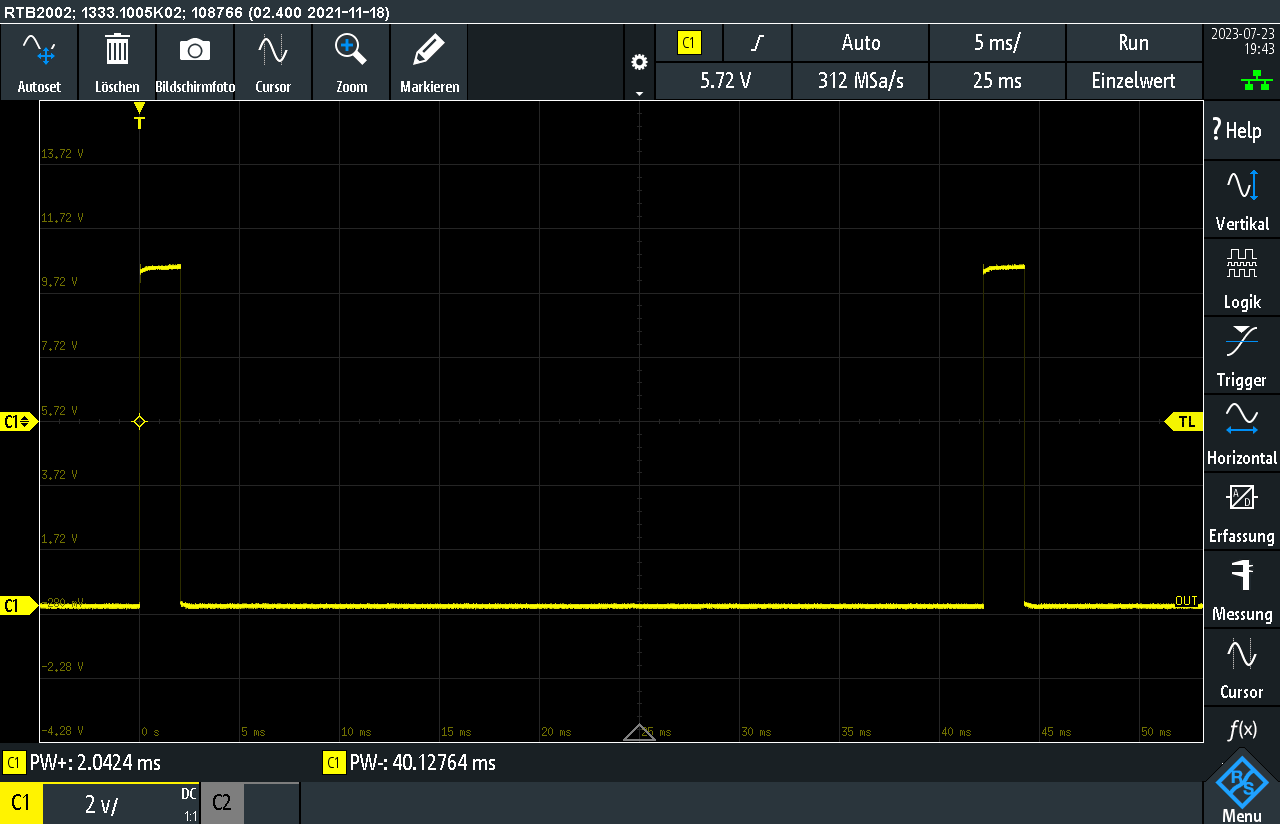
RTB2002: 1333.1005K02: 108766 (02.400 2021-11-18) 2023-07-23 19:43 Autoset Löschen Bildschirmfoto Cursor Zoom Markieren 5 ms/ 25 ms Run Einzelwert 13,72 V 11,72 V 5,72 V 7,72 V 5,72 V C1 3,72 V 1,72 V C1 PW+: 2.0424 ms C1 2 v/ C1 PW-: 40.12764 ms -2,28 V -4,28 V 0 s 5 ms 10 ms 15 ms 20 ms 25 ms 30 ms 35 ms 40 ms 45 ms 50 ms Vertikal Logik Trigger TL Horizontal Erfassung Messung Cursor f(x) Menu
in „Hilfe bei Schaltung mit 555 Timer und Transistor“ · Analoge Elektronik und Schaltungstechnik · · Oszi-Bilder
-
Datei
PWM_STEP_INKREASE.h
Phaseninkrementierung muss Integer sein. Phasenende von 65535 sorgt für automatischen überlauf. Mindestens 100 PWM Schritte für eine 1% Genauigkeit. Daraus ergibt sich Nmin = 128 bei deltaPhi = 512 => maximale Frequenz bei 16000 Hz deltaPhi = 65536 / N */ int selectFrequency(int adcResult){ if (adcResult > 230)
in „uint16 Variable in Hardwareregister speichern“ · Mikrocontroller und Digitale Elektronik ·
-
Datei
adc-pwm-led.c
ADSC)) // Warte, bis Konvertierung abgeschlossen ist ; return ADC; // Gib den ADC-Wert zurück } void PWM_Init() { TCCR0A = (1 << COM0A1) | (1 << WGM01) | (1 << WGM00); // Fast PWM-Modus konfigurieren TCCR0B = (1 << CS01); // Prescaler auf 8 setzen DDRD |= (1 << PD6); // PD6 (Pin 6) als PWM-Ausgang setzen } void SetPWM(uint8_t dutyCycle) { OCR0A = dutyCycle; // PWM Duty Cycle setzen } int main(void) { ADC_Init(); // ADC initialisieren PWM_Init(); // PWM initialisieren DDRH |= (1 << PH6) | (1 << PH5); // PH6 und PH5
-
Datei
PWM_Modulation_Code.txt
uint8_t LEDnummer = 0; int LEDwert[4]; //Binärwert der jeweiligen LED int PWMstatus[4]; // aktueller Modulationsgrad der LED uint8_t PWMtime = 0; uint8_t PWMlevel = 0; uint8_t LEDon = 15; uint8_t LEDoff[3]; uint8_t LEDoff25 = 0; uint8_t LEDoff50 = 0; uint8_t LEDoff75 = 0; uint16_t ADC_Taste = 1023; uint8_t status = 0; uint8_t Tasterdelay = 0; int main(void) { LEDwert[0] = 1; LEDwert[1] = 2; LEDwert[2] = 4; LEDwert[3] = 8; PWMstatus[0] = 4; PWMstatus[1] = 4; PWMstatus[2] = 4; PWMstatus[3] = 4; LEDoff[0] = 0; // LEDs bei Tastgrad 25% ausschalten LEDoff[1] = 0; // LEDs bei Tastgrad 50% ausschalten
in „PWM-Modulation“ · Mikrocontroller und Digitale Elektronik ·
-
Datei
nex_4_pwm.vhd
); end nex_4_pwm; architecture Behavioral of nex_4_pwm is signal pwm_zaehler: unsigned(15 downto 0):=(others => '0'); begin led <= sw; RGB1_Red <= '1' when pwm_zaehler <= unsigned(sw); RGB1_Green <= '1' when pwm_zaehler <= unsigned(sw); RGB1_Blue <= '1' when pwm_zaehler <= unsigned(sw); process begin wait until rising_edge(clk); pwm_zaehler <= pwm_zaehler +1; end process; end Behavioral;
-
Datei
FastSoftPWM.asm
.include "m1284pdef.inc" .equ wt_enable=1 .equ eff1=1 .equ eff2=1 .equ eff3=1 .equ eff4=1 .equ eff5=1 .equ eff6=1 .equ eff7=1 .equ eff8=1 .equ eff9=1 .equ eff10=1 .equ eff11=1 .equ eff12=1 .equ eff13=1 .equ eff14=1 .equ eff15=1 .equ eff16=1 .equ eff17=1 .equ eff18=1 .equ eff19=1 .equ timer=21 .equ leds=256 .equ output_bits=10 ;not to be changed without major code adaption! .equ ul=53 ;upper limit of LED intensity, depends on the number of entries in the intensity lookup table .equ smooth=1 .include "convert_macro.asm" ;macros for translating logical LED numbers into real "addresses" at the driver
-
Datei
stm32-pwm.c
/* USER CODE BEGIN Header */ /** ****************************************************************************** * @file : main.c * @brief : Main program body ****************************************************************************** * @attention * * <h2><center>© Copyright (c) 2021 STMicroelectronics. * All rights reserved.</center></h2> * * This software component is licensed by ST under BSD 3-Clause license, * the "License"; You may not use this file except in compliance with the * License. You may obtain a copy of the License at: * opensource.org/licenses/BSD-3-Clause * *********************
in „PWM-Signal mit STM32 messen“ · Mikrocontroller und Digitale Elektronik ·
-
Datei
PWM-TEST_886.asm
init bank0 clrf PORTA clrf PORTB clrf PORTC bank1 movlw b'11111001' movwf TRISC ; RC1/2 = Ausgang (PWM) return ;****************************************************************** setpwm bank1 movlw 0xFF ; frequenzbestimmend movwf PR2 clrf PWM1CON clrf ECCPAS bank0 movlw b'00000101' ; TMR2 on, Prescaler = 4 movwf T2CON movlw b'00001100' ; PWM-Mode mit Standardauflösung 10 bit movwf CCP1CON movwf CCP2CON nop ; Initialwerte für die clrf CCPR1L ; duty cycle-Register clrf CCPR2L return ;*******************************************************
in „PIC16F886 PWM-Programm läuft nicht“ · Mikrocontroller und Digitale Elektronik ·
-
Datei
tb_pwm2.vhd
LIBRARY ieee; USE ieee.std_logic_1164.ALL; ENTITY tb_pwm2 IS END tb_pwm2; ARCHITECTURE behavior OF tb_pwm2 IS -- Component Declaration for the Unit Under Test (UUT) COMPONENT pwm2 PORT( CLK : IN std_logic; SW : IN std_logic_vector (5 downto 0); PWM_Value
in „DC Motor, PWM, Drehrichtung, Drehzahl“ · FPGA, VHDL & Co. ·
-
Datei
PWM-diff-20210120.diff
diff -r -u 1.42m-20210120/tools_signal.c dev-m/tools_signal.c --- 1.42m-20210120/tools_signal.c 2021-01-12 10:29:02.000000000 +0100 +++ dev-m/tools_signal.c 2021-01-21 18:27:34.000000000 +0100 @@ -274,6 +274,7 @@ uint16_t Step2; /* step size */ uint16_t Temp; /* temporary value */ uint32_t Value; /* temporary value */ + uint32_t CycleLenUs; /* length of one cycle in us */ /* local constants for Flag (bitfield) */ #define RUN_FLAG 0b00000001 /* run / otherwise end */ @@ -435,6 +436,7 @@ Value = CPU_FREQ * 50; /* scale to 0.01Hz and /2 */ Value /= Prescaler; Step = 2; /* 2 decimal places */ + CycleLenUs
-
Datei
ADC_PWM_2.c
/Messung starten //Warten auf Ergebnis ADCSRA |= (1 << ADSC); while (ADCSRA & (1 << ADSC)); } void pwm_init(){ //Ausgänge setzen DDRA |= (1 << PA6) | (1 << PA7) | (1 << PA5); DDRB |= (1 << PB2); //Timer 0 (8 Bit) //Löschen von Bits: OC0A/OC0B Bit 7 + 6 //Art der Wellenform erzeugung: PWM, Phase Correct
in „ADC und PWM am ATtiny84“ · Mikrocontroller und Digitale Elektronik ·
-
Datei
PWM_Dimmer_entprellt.txt
(Timer1) TIMSK = 1<<OCIE1A; // (Timer1) LED_DDR = 1<<LED0; KEY_PORT |= (1<<KEY0); // Pullup on /* PWM für Dimmer */ TCCR0A = ( 1 << COM0A1 ) | ( 1 << WGM00 ) | ( 1 << WGM01 ); // Clear OC0A/OC0B on Compare Match // Fast PWM , TOP = 0xFF TCCR0B = ( 1 << CS01 ) | ( 1 << CS00 ); // Mode: Normal | F_Proz
in „Eintastendimmer und Taster Entprellung“ · Mikrocontroller und Digitale Elektronik ·
-
Datei
PWM_Dimmer_entprellt.txt
From prescaler) OCR0A = 0; // LED aus sei(); for(;;){ // main loop if( (get_key_short( 1<<KEY0 ))) if(pwm > 0) pwm = 0; else pwm = 255; if( get_key_long_r( 1<<KEY0 ) || get_key_rpt_l( 1<<KEY0 )) { pressed = 1; if( direction ) { if( pwm < 255 ) ++pwm; } else { if( pwm > 0 ) --pwm; } } else if( pressed ) { pressed = 0; direction = 1 - direction; } OCR0A = pwm; //_delay_ms(10); } return 0; }
in „Eintastendimmer und Taster Entprellung“ · Mikrocontroller und Digitale Elektronik ·