CAN Raw Terminal
Adapter: J2534
Port:
Configure
Close
Command ID: 6D1
Transmit Bytes: 90 45 62 11
Macro:
Run
See Help
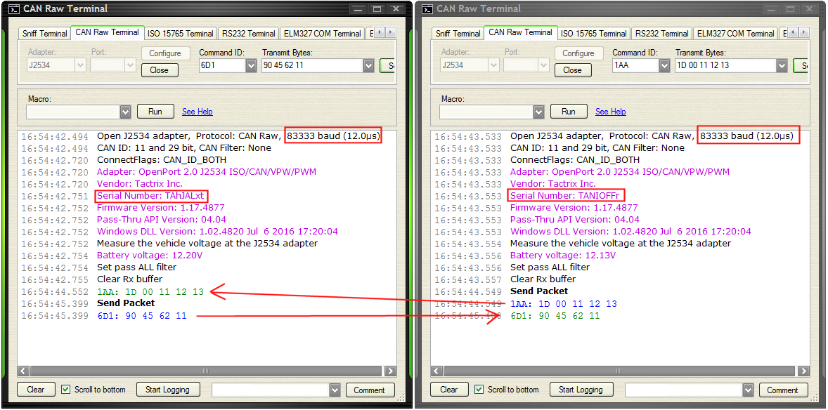
Open J2534 adapter, Protocol: CAN Raw, 83333 baud (12.0µs)
CAN ID: 11 and 29 bit, CAN Filter: None
ConnectFlags: CAN_ID_BOTH
Adapter: OpenPort 2.0 J2534 ISO/CAN/VPW/PWM
Vendor: Tactrix Inc.
Serial Number: TANIOFr
Firmware Version: 1.17.4877
Pass-Thru API Version: 04.04
Windows DLL Version: 1.02.4820 Jul 6 2016 17:20:04
Measure the vehicle voltage at the J2534 adapter
Battery voltage: 12.20V
Set pass ALL filter
Clear Rx buffer
1AA: 1D 00 11 12 13
Send Packet
6D1: 90 45 62 11
a positive supply via a pull-up resistor when connected to the output stages of a device. Data transfer may be initiated only when the bus is not busy. 7.1 Bit transfer One data bit is transferred during each clock pulse. The data on the SDA line must remain stable during the HIGH period of the clock
Vielleicht wäre es sinnvoll, sich zuerst für *EINEN* Transfer-Modus zu entscheiden: *Entweder* Ringpuffer-Modus *oder* Einzelschuss-Modus. Beides gleichzeitig macht keinen Sinn. NSS wird nicht benutzt? Die 12 da mehrfach rein zu schreiben, ist keine gute
memory access controller (DMA) RM0360 166/775 RM0360 Rev 5 10.6.4 DMA channel x number of data to transfer register (DMA_CNDTRx) Address offset: 0x0C + 0x14 * (x - 1), (x = 1 to 5) Reset value: 0x0000 0000 Bit 4 DIR: Data transfer direction This bit must be set only in memory-to-peripheral and peripheral-to-memory
reaches 06h, it will register for monitoring the measured voltages. Figure 2 shows a general data transfer format using the I 2C. The bereset to00handcontinuetheincrement. UponaStop LTC4151isaread-writeslavedeviceandsupportsSMBus condition, theregisteraddressisreset to00h. If desired, theReadPageandWritePagesupportcanbedisabledby
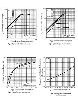
Capacitance ––– 1077 ––– VGS = 0V C oss Output Capacitance ––– 360 ––– pF VDS= 15V C rss Reverse Transfer Capacitance ––– 110 ––– ƒ = 1.0MHz Avalanche Characteristics Parameter Typ. Max. Units E Single Pulse Avalanche Energy ––– 98 mJ AS IAR Avalanche Current c ––– 25 A Diode Characteristics Parameter
Bei TCP Streams kann man zB. die ACKs des Transfer-Windows verzögern und so die Rate der eingehenden Pakete (etwas verzögert zwar) durchaus limitieren. Ausgehende Pakete ja sowieso…
Serial Adapter. They are 16550 high-speed UART compatible and support 16-byte FIFO buffers for transfer rates from 50baud to 115.2Kbaud. 8.1 Connector COMA is available through the X10 connector (10 pins) and COMB through the X13 connector (10 pins). To have the signals available on the standard serial
they are high section lugs, blades and so on) can dissipate heat from the unit but they may also transfer heat generated in outer connections into the capacitor. Forthisreason,itisnecessarytokeeptheconnectionsleadingtothecapacitorscoolerthanthecapacitoritself.Important:specialcareisnecessary when designing
Gerhard O. schrieb im Beitrag #7640149: > Ein Transfer dauert bei ansonsten gleichen Einstellungen genauso lang > wie ein 16-bit Transfer. Nö. Du unterlässt es hartnäckig die realen Umgebungsbedingungen zu nennen. Also den vorher so genannten _Kontext
Wastl schrieb im Beitrag #7640155: > Gerhard O. schrieb: >> Ein Transfer dauert bei ansonsten gleichen Einstellungen genauso lang >> wie ein 16-bit Transfer. > > Nö. Du unterlässt es hartnäckig die realen Umgebungsbedingungen > zu nennen. Also den vorher so genannten
, gesamte Latenz von Daten in einem System bei einem Schreib- und Rücklesevorgang RTL: Register Transfer Language, textuelle Beschreibung einer Schaltung auf Registerebene beim Chip- und FPGA-design S. SAR: Specific Absorption Rate: eine Maßzahl die angibt, wieviel Energie der menschliche Körper bei
Aus den Kommentaren des Youtube Videos: "PCB Circuit Board Thermal Transfer Paper" Google findet dazu etliche Treffer, u.a. bei Amazon und Aliexpress.
Ich nutze und optimiere seit Jahren die PCB-Herstellung per Toner-Transfer und ohne das YT-Video/Links gesehen zu haben trage ich mal folgendes bei: Ich hatte vor paar Monaten dies "spezielle TonerTransfer-Papier" aus China bestellt, gelbe A4-Blätter mit gummiartiger/
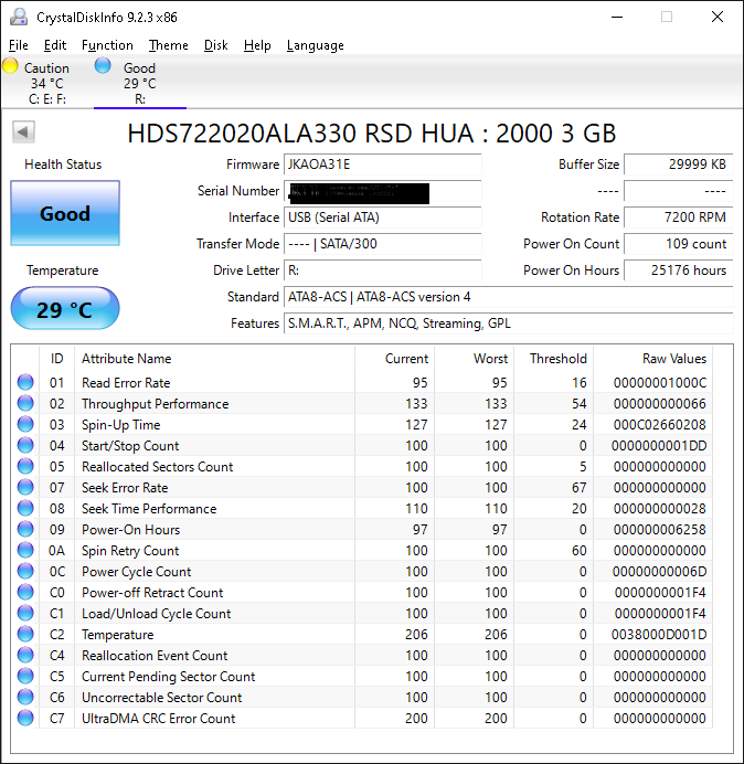
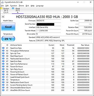
Firmware JKAOA31E
Buffer Size 29999 KB
Serial Number
Interface USB (Serial ATA)
Rotation Rate 7200 RPM
Transfer Mode ----| SATA/300
Power On Count 109 count
Temperature 29 °C
Power On Hours 25176 hours
Drive Letter R:
Standard ATA8-ACS
Features S.M.A.R.T., APM, NCQ, Streaming, GPL
ID Attribute Name Current
current –I0 0.5 mA Output current Pin 3 –I 0.2 2 mA 0 Supply voltage compensation, figure 8 Current transfer gain7 3/I Pins 7, Pin 3 Pins 1 and 2 open G 14 17 20 i Reverse current V (R6)= V3= V 7 0 Pin 3 " IR 2 mA Load current detection, V 7 0, figure 9 Transfer gain I3/V 1 G 0.280 0.320 0.370 mA/mV Offset
current +I0 0.5 mA Output current Pin 4 +I 0.2 2 mA 0 Supply voltage compensation, figure 9 Pin 15 Transfer gain I15 I5 Pin 15/5 Gi 14 17 20 (Pins 1 and 2 open) Output offset current V (R6)= V 15= V 5 0 " I0 2 mA Load current detection, R 1 =R2= 3 kW, V 15 = 0, V5= V 6 V f8,ure 10 Transfer gain I5/150 mV
Figure 9: Drive speed set point reaction time The speed is set according to the Digital control: transfer function PWM input (see Figure 11). 9.4 Digital control: transfer function PWM input The transfer function PWM input is the relation between the Drive speed and the duty cycle on the pin digital PWM
peak, 2.2 2.5 V IF= 0 dv/dt Critical Rate of Rise of Off−State VoltagIF= 0, DRM = 600 V 1000 V/ms TRANSFER CHARACTERISTICS Symbol DC Characteristic Test Conditions Device Min Typ Max Unit IFT LED Trigger Current, Main Terminal MOC3051M 15 mA Either Direction Voltage = 3 V (Note 2) MOC3052M 10 MOC3053M
Transfer Ratio (Collector-Base) CTR CB 0.25 % F =10 mA, CB =9.3 V IL2 Saturated Current Transfer Ratio (Collector-Emitter) CTR CESAT 170 % F =10 mA, CE=0.4 V Current Transfer Ratio (Collector-Emitter) CTR CE 100 200 500 % F =10 mA, CE=10 V Current Transfer Ratio CTR 0.25 % I =10 mA, V =9.3 V CB F CB IL5 Saturated Current Transfer Ratio (Collector-Emitter) CTR CESAT 100 % F =10 mA, CE=0.4 V Current Transfer Ratio (Collector-Emitter) CTR CE 50 130 400
been removed. • Double fluff filter 650474 has been installed. 6.2.1 Preparing conversion kit ► Transfer microswitch and plunger from the old carrier. 2. Install condensation pump and condensation sensor. 3. Install condensation tank housing. 4. Connect hose between condensation tank housing and condensation
Ich vermute die Messung oder I²C Transfer wird durch Hochfrequente störungen aus dem Netzteil gestört. Der fühler mag isoliert sein, die HF- Störströme koppeln jedoch kapazitiv und umgehen dadurch die isolation, sobald du ihn berührst.
Flip B. schrieb im Beitrag #7627625: > Ich vermute die Messung oder I²C Transfer wird durch Hochfrequente > störungen aus dem Netzteil gestört. Der fühler mag isoliert sein, die > HF- Störströme koppeln jedoch kapazitiv und umgehen dadurch die > isolation, sobald du ihn
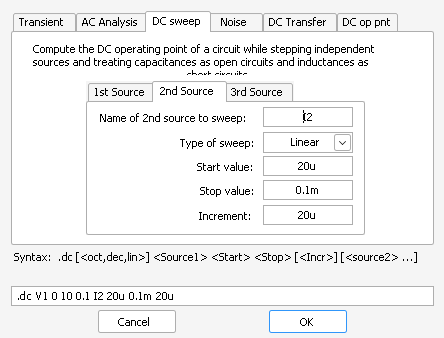
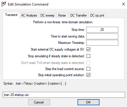
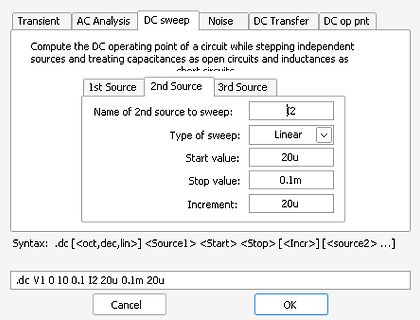
Transient AC Analysis DC sweep Noise DC Transfer DC op pnt
Compute the DC operating point of a circuit while stepping independent sources and treating capacitances as open circuits and inductances as short circuits.
1st Source 2nd Source 3rd Source
Supports SSP, UART, I2C, I2S, ADC, DAC, Timer, PWM, GPIO, etc., can be used for memory-to-memory transfer. Standard JTAG test / debug interface and a serial wire debugging and serial wire tracking port option. Simulation trace module supports real-time tracking. 4 low-power modes: sleep, deep sleep
Time Division Multiplex Support – High-speed Continuous Data Stream Capabilities with 32-bit Data Transfer ! One Two-wire Interface (TWI) – Master Mode Support Only, All Two-wire Atmel EEPROMs Supported ! Multimedia Card Interface (MCI) – Compliant with Multimedia Cards and SD Cards – Automatic Protocol
kann man wenigstens die Anschlüsse am Display zuordnen. https://image.jimcdn.com/app/cms/image/transf/none/path/s80a1800cdded55f0/image/i7075d8d6a2166656/version/1405782140/image.jpg da ist das Foto kaum besser, aber es sieht jedenfalls nach zweizeilig aus, ob 16 oder 20 Zeichen pro Zeile ist schlecht
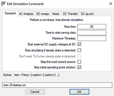
Edit Simulation Command
Transient AC Analysis DC sweep Noise DC Transfer DC op pnt
Perform a non-linear, time-domain simulation.
Stop time: 20
Time to start saving data:
Maximum Timestep:
Start external DC supply voltages at 0V:
Stop simulating if steady state is detected
YUZ ® standard products shall ® also apply to such Bourns custom products. Users shall not sell, transfer, export or re-export any Bourns▯WYVK\J[Z▯VY▯[LJOUVSVN`▯MVY▯\ZL▯PU▯HJ[P]P[PLZ▯^OPJO▯PU]VS]L▯[OL▯ KLZPNU▯▯KL]LSVWTLU[▯▯WYVK\J[PVU▯▯\ZL▯VY▯Z[VJRWPSPUN▯VM▯U\JSLHY▯▯JOLTPJHS▯VY▯IPVSVNPJHS▯^LHWVUZ▯VY▯TPZZPSLZ
some real-time function and is not ready to start communication with the master. 3. During the transfer, the receiver gets data or commands that it does not understand. 4. During the transfer, the receiver cannot receive any more data bytes. 5. A master-receiver must signal the end of the transfer to
.........................................................22 FIGURE 8-10 :DEFINITION OF THE DATA TRANSFER CONDITI.........................................................................................22 FIGURE 8-11 :OSCILLATORC IRCUIT ANDDISPLAYT IMEG ENERATOR .......................................
schneller sein. Und natuerlich ohne "Akustikmanagement". Der Einbruch der Uebertragungsrate beim Transfer, faellt weit weniger heftig aus, als bei SSDs, wenn deren Cache vollgeschrieben ist.
using DSACK signals. Wait states are generated either from the device or port being accessed. Data transfer and size acknowledge signals ~DSACK0 and ~DSACK1 control bus speed (by adding wait states) and dynamic bus sizing for circuitry that does not generate its own data transfer and size acknowledge signals
Synchro nur eine begrenzte Auswahl an Events. Ich brauche ja einmal den Sample-Rate-Timer für den DMA-Transfer und einmal den Synchro-Trigger (CC oder Update) des Impulstimers als Synchro.
Standgehäuse. Ansonsten könnte man sowas mit einer kleinen USV und einem Umschalter ("Power Transfer Switch") lösen, aber alleine diese Switche sind ebenfalls ziemlich teuer. Wahrscheinlich ist eine ausreichen große USV am Ende nicht viel teurer.
addresDPassignment is as follows: B0 B1 B2 B3 B4 B5 B6 B7 - 68H DIG1 66CH DIG3 i 6EH DIG4 Note: When power up, transfer data to RAM first, and then setup display on. 4.2、Control Instruction The system instruction must be input before sending display instructions,that is,input byte 1 is the system instruction,and input
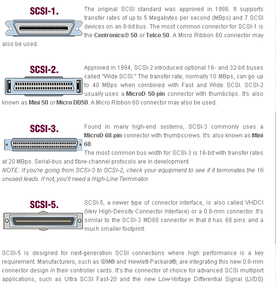
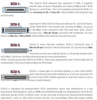
SCSI-1. The original SCSI standard was approved in 1986. It supports transfer rates of up to 5 Megabytes per second (Mbps) and 7 SCSI devices on an 8-bit bus. The most common connector for SCSI-1 is the Centronics® 50 or Telco 50. A Micro Ribbon 60 connector may also be used
heatsink; 4 leads BCX56 SC-62 plastic surface-mounted package; collector pad for good SOT89 heat transfer; 3 leads [1]Valid for all available selection groups. [2]Also available in SOT54A and SOT54 variant packages (see Section 2 and Section 9). 4. Marking Table 5. Marking codes Type number Marking code
LTA - long term allocation, MNCC - margin from non-coordinated capacity calculation, PTDF- power transfer distribution factor, R - minimum RAM factor, RAM - remaining available margin Langfristanalyse 2030 (V2022) 01.09.2023 65 Inhaltsverzeichnis / Gliederung I.4. Eingangsparameter und Methodik – Flow-Based
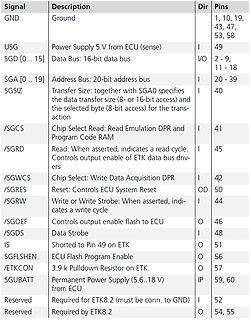
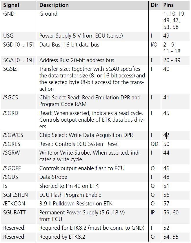
16-bit data bus I/O 2 - 9, 11 - 18
SGA [0 .. 19] Address Bus: 20-bit address bus I 20 - 39
SGSIZ Transfer Size: together with SGA0 specifies the data transfer size (8- or 16-bit access) and the selected byte (8-bit access) for the transaction I 40
/SGCS Chip Select Read: Read Emulation DPR and Program
"NDT[15:0]: number of data items to transfer (0 up to 65535) ... This register decrements after each DMA transfer. Once the transfer is completed, this register can either stay at zero (when the stream is in normal mode) or be reloaded automatically
implementiert. Das dürfte aber keine Probleme machen. Bei einem solchen Wandler hat man eine STF (signal transfer function) und eine NTF (noise transfer function). Je nach Wandler kann die STF einfach 1 sein oder das Signal formen. Die NTF ist so ausgelegt, dass das eingeführte Quantisierungsrauschen spektral
Programming Lock for Software Security and USB USB 2.0 Full-speed Device Module with Interrupt on Transfer Completion – Complies fully with Universal Serial Bus Specification REV 2.0 Controller – 48 MHz PLL for Full-speed Bus Operation : data transfer rates at 12 Mbit/s – Fully independant 176 bytes USB
adjusted, must be resent via the interface from the personal computer. AUTOSTART is not possible. A transfer sequence consists of: • address (RS485 interface only) • command • space ( ⇔, Hex: 20) • parameter (the character separating decimals in a group is the period) • end of file (↵; Hex: 0D) The commands
server[/code] Was mach ich falsch? Die Anleitung ist von https://opensource.com/article/22/10/transfer-files-windows-linux-pscp Edit: Habe WinSCP gefunden, damit gehts. Statt 11,3MB/s mit knapp 2MB/s, und es kann im Gegensatz zu Filezilla nicht nach der Dateigröße gehen und unterschiedliche Files
of compensation design is to shape at the location of the ESR zero. Determine C6 the converter transfer function to get a desired by the equation: loop gain. The system crossover frequency C2 R ESR where the feedback loop has the unity gain is C6 = important. Lower crossover frequencies result R3 in

 Bild
Bild

 Bild
Bild
 Bild
Bild
 Bild
Bild
 Bild
Bild
 Bild
Bild
 Bild
Bild
 Bild
Bild
 Bild
Bild
 Bild
Bild
 Bild
Bild