erzeugen kann, dann ergibt das eben eine Horizontalauflösung von 4000000/15625 * (52 µs / 64 µs) = 208 Pixel. Weblinks: Serielles Terminal von Ingmar Meins (AT90S8535, PAL) MAHPONG-Spiel von Marcus Hasenstab (AT90S8515, PAL) TV Bild mit AVR und AVR) Videogenerator, 40x25 Zeichen, nur 60% CPU Auslastung
alten TVs oder Videorecordern. Single-Channel Monochrome On-Screen Display with Integrated EEPROM MAX7456 Eagle lib MAX7456 MAX7456 Schaltung + PIC16F ASM Beispiel AVR Bascom beispiel
ich erst so ab 50 oder gar 100 Stück anraten. Aber das Ätzen von 15-20 Platinen von Hand mit TQFP 208 zu fertigen ist nimmer grad einfach. Deswegen kommt man mit extern Fertigen lassen besser davon.
Liste wünschen darf, dann den LPC2368. Man muss bei dieser Aufstellung aber sagen, dass NXP die max. Storage Temp. mit +125°C angibt, aber keine max. operating Temp. Atmel deklariert seine Chips auch als Automotive, gibt eine Storage-Temp von 125°C an, ist aber ehrlich genug die Operting Temp mit
MECHANICAL DATA Case:JEDEC R--1,molded plastic Terminals: Axial lead ,solderable per MIL- STD-202,Method 208 Dimensions in millimeters Polarity: Color band denotes cathode Weight: 0.007ounces,0.20 grams Mounting position: Any MAXIMUM RATINGS AND ELECTRICAL CHARACTERISTICS Ratings at 25 ambient temperature
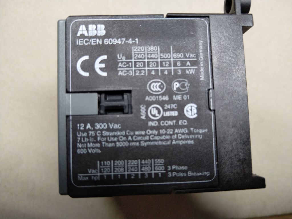
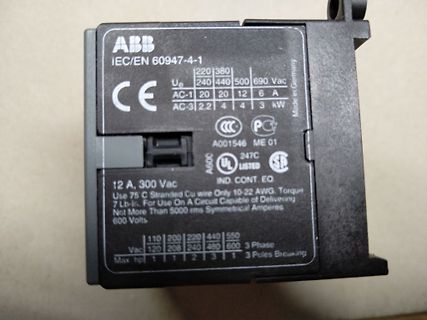
Capable of Delivering Not More Than 5000 rms Symmetrical Amperes 600 Volts
110 200 220 440 550 Vac 120 208 240 480 600 3 Phase
Max hp 1 1 2 3 1 3 Poles Breaking
Schrittweite 24Bit Samplerate 25usec (40KHz) Bild 1: SAW-Wellenform ca. 2031Hz mit Phasen-Jitter (max. 25usec / Div. 100µsec) Bild 2: SAW-Wellenform ca. 2031Hz mit Phasen-Jitter (max. 25usec / Div. 2msec) Bild 3: Saw-Wellenform ca. 2038Hz ohne Phasen-Jitter (Div. 100µsec) Bild 4: Saw-Wellenform
Möglichkeit zum Austausch mit anderen Gleichgesinnten war gleich null. Description The MAXIM MAX260/MAX261/MAX262 CMOS dual second-order universal switched-capacitor active filters allow microprocessor control of precise filter functions. No external components are required for a variety of bandpass
CHARACTERISTICS Test Conditions Value Symbol Parameter V V I V T Low 25⋅C T High Unit (V) (V) ( A) (V)D Min. Max. Min. Typ. Max. Min. Max. IL Quiescent 0/5 5 5 0.04 5 150 Current HCC 0/10 10 10 0.04 10 300 Types 0/15 15 20 0.04 20 600 A 0/20 20 100 0.08 100 3000 0/5 5 5 0.04 5 150 HCF Types 0/10 10 10 0.04 10
Symbol Parameter TA= 25 Co -40 to 85 C -55 to 125 C o Unit V CC 54HC and 74HC 74HC 54HC (V) Min. Typ. Max. Min. Max. Min. Max. V IH High Level Input 2.0 1.5 1.5 1.5 Voltage 4.5 3.15 3.15 3.15 V 6.0 4.2 4.2 4.2 VIL Low Level Input 2.0 0.5 0.5 0.5 Voltage 4.5 1.35 1.35 1.35 V 6.0 1.8 1.8 1.8 V OH High Level
Insulation Resistance 10 MΩ / between unshielded wire and frame at 500 VDC/min Dielectric Strength 5 mA Max. / measured between lead wire (+) and frame at 500 VAC/min 2.4. RPM Signal Specification Customer Circuit FAN Green lead R Voltage (Vcc) Link Output ** Please select “R” to make “Link” less than 5mA Waveform ** Vcc: 13.2V Max Link 5 mA Max Output Waveform LOCK VCC VOH VOHor VOLoutput is depending on the looked rotor position. VOL 2 pulses / rotation 2.5. Speed Control System PWM Control Input (W) V High Level PWM frequency
Symbol Parameter TA= 25°C -40 to 85°C -55 to 125°C Unit VI VO |O | V DD (V) (V) ( A) (V) Min. Typ. Max. Min. Max. Min. Max. IL Quiescent Current 0/5 5 0.04 5 150 150 0/10 10 0.04 10 300 300 A 0/15 15 0.04 20 600 600 0/20 20 0.08 100 3000 3000 VOH High Level Output 0/5 5 4.95 4.95 4.95 Voltage 0/10 10
Ring Die Construction for Transient Protection TO-220AB · Low Power Loss, High Efficiency L Dim Min Max · High Surge Capability B M · High Current Capability and Low Forward A 14.22 15.88 Voltage Drop C B 9.65 10.67 D · For Use in Low Voltage, High Frequency K C 2.54 3.43 Inverters, Free Wheeling, and
to Insertion Return Loss Differential Common Crosstalk Loss dB min Mode Mode dB min Part Number dB max Rejection Rejection dB min dB min 1MHz to 1MHz to 30MHz to 60MHz to 100MHz 30MHz 60MHz 80MHz 100kHz to 100MHz 1MHz 30MHz 60MHz 100MHz 0810-1XX1-01 -1.0 -18 18 - 20 log -12 40 30 -65 -45 -37 -35 (f/30MHz
aDDVvalues is 0,3%/⋅C) Test Conditions Value VI VDD TLow* 25⋅ C THigh Symbol Parameter Unit (V) (V) Min. Max. Min. Typ. Max. Min. Max. L Quiescent 0/ 5 5 0.25 0.01 0.25 7.5 Device 0/10 10 0.5 0.01 0.5 15 Current (allCC switches Types 0/15 15 1 0.01 1 30 ON or all switches 0/20 20 5 0.02 5 150 A OFF) 0/ 5 5
aDDVvalues is 0,3%/⋅C) Test Conditions Value VI VDD TLow* 25⋅ C THigh Symbol Parameter Unit (V) (V) Min. Max. Min. Typ. Max. Min. Max. L Quiescent 0/ 5 5 0.25 0.01 0.25 7.5 Device 0/10 10 0.5 0.01 0.5 15 Current (allCC switches Types 0/15 15 1 0.01 1 30 ON or all switches 0/20 20 5 0.02 5 150 A OFF) 0/ 5 5
(0x0001) SCT Support Level: 0 Device State: Active (0) Current Temperature: 0 Celsius Power Cycle Max Temperature: 0 Celsius Lifetime Max Temperature: 0 Celsius SCT Temperature History Version: 2 Temperature Sampling Period: 10 minutes Temperature Logging Interval: 10 minutes Min/Max recommended Temperature: 0/70 Celsius Min/Max Temperature Limit: -5/75 Celsius Temperature History Size (Index): 478 (373) Index Estimated Time Temperature Celsius 374 2013-09-26 07:40 ? - ... ..(476 skipped). .. - 373 2013-09-29 15:10 ? - SCT
R. Max schrieb im Beitrag #3151144: > OK, das Thema ist eigentlich durch, Schon länger, das ist hier nur noch etwas Spaß an der Bastelfreude. > aber als Variante der > Schieberegister-Version möchte
reichlich Anwendungsmöglichkeiten. Ein halb so großer PIC hätte es auch gut getan. Der Code ist gerade 208 Bytes groß, und im RAM 11 Bytes belegt. Trotz des wenig optimalen Hi-Tech-Lite-Compilers.
Symbol Test Conditions Quadrant T12 BTA/BTB12 Unit T1235 TW SW CW BW IGT (1) V = 12 V R = 30 I - II - MAX. 35 5 10 35 50 mA V D L GT I - II - MAX. 1.3 V V V = V R = 3.3 k I - II - MIN. 0.2 GD D DRM L V Tj = 125°C I (2) I = 100 mA MAX. 35 10 15 35 50 mA H T L IG= 1.2 GT I - III MAX. 50 10 25 50 70 mA II
Symbol Test Conditions Quadrant T12 BTA/BTB12 Unit T1235 TW SW CW BW IGT (1) V = 12 V R = 30 I - II - MAX. 35 5 10 35 50 mA V D L GT I - II - MAX. 1.3 V V V = V R = 3.3 k I - II - MIN. 0.2 GD D DRM L V Tj = 125°C I (2) I = 100 mA MAX. 35 10 15 35 50 mA H T L IG= 1.2 GT I - III MAX. 50 10 25 50 70 mA II
3 quadrants) T16 BTA16 / BTB16 Symbol Test Conditions Quadrant Unit T1635 SW CW BW GT (1) I - II - MAX. 35 10 35 50 mA VD= 12 V R =L33 Ω VGT I - II - MAX. 1.3 V V VD= V DRM R L 3.3 kΩ GD Tj= 125°C I - II - IMIN. 0.2 V IH(2) T = 500 mA MAX. 35 15 35 50 mA I - III 50 25 50 70 L G = 1.2 GT MAX. mA II 60
3 quadrants) T16 BTA16 / BTB16 Symbol Test Conditions Quadrant Unit T1635 SW CW BW GT (1) I - II - MAX. 35 10 35 50 mA VD= 12 V R =L33 Ω VGT I - II - MAX. 1.3 V V VD= V DRM R L 3.3 kΩ GD Tj= 125°C I - II - IMIN. 0.2 V IH(2) T = 500 mA MAX. 35 15 35 50 mA I - III 50 25 50 70 L G = 1.2 GT MAX. mA II 60
.................................................. PC-A011, PC-A111 Das EVG begrenzt den Strom auf max. 2mA V 5V I max. 2mA 850us • statische Stromsenke (0Hz) .......................................................................... PCA Excel Das EVG begrenzt den Strom auf max. 2mA V 5V I max. 2mA •
Symbol Parameter V V |I | V T A= 25°C -40 to 85°C -55 to 125°C Unit I O O DD (V) (V) (μA) (V) Min Typ Max Min Max Min Max 0/5 5 0.02 1 30 30 Quiescent 0/10 10 0.02 2 60 60 L μA current 0/15 15 0.02 4 120 120 0/20 20 0.04 20 600 600 High level 0/5 <1 5 4.95 4.95 4.95 VOH output 0/10 <1 10 9.95 9.95 9.95
SURFACE MOUNT SCHOTTKY BARRIER DIODE Features · Low Turn-on Voltage SOT-23 · Fast Switching A Dim Min Max · PN Junction Guard Ring for Transient and ESD Protection A 0.37 0.51 B B C 1.20 1.40 C 2.30 2.50 Mechanical Data TOP VIEW E D D 0.89 1.03 · Case: SOT-23, Molded Plastic G E · Case material - UL Flammability
20 I = DC Current (A) L = EffectivePath Length (cm) OD (nom. - bare core) 33.02 mm 1.300 in 10 e (max. - after coating) 33.53 mm 1.320 in 0 (nom. - bare core) 19.81 mm 0.780 in 1 10 100 1,000 ID (min. - after coating) 19.30 mm 0.760 in H - DC MagnetizingForce (Oe) Ht (nom. - bare core) 11.10 mm 0.437 in (max. - after coating) 11.73 mm 0.462 in 106 %InitialPerm vs. Peak AC FluxDensity - Mix-06 (8.5µ) Mass (approximate) 29 grams s 105 o A e Eff. Mag. Cross Section 0.698 cm² i n Le- Eff. Mag. Path Length 8.28
20 I = DC Current (A) L = EffectivePath Length (cm) OD (nom. - bare core) 33.02 mm 1.300 in 10 e (max. - after coating) 33.53 mm 1.320 in 0 (nom. - bare core) 19.81 mm 0.780 in 1 10 100 1,000 ID (min. - after coating) 19.30 mm 0.760 in H - DC MagnetizingForce (Oe) Ht (nom. - bare core) 11.10 mm 0.437 in (max. - after coating) 11.73 mm 0.462 in 106 %InitialPerm vs. Peak AC FluxDensity - Mix-06 (8.5µ) Mass (approximate) 29 grams s 105 o A e Eff. Mag. Cross Section 0.698 cm² i n Le- Eff. Mag. Path Length 8.28
Gehäuse besitzt. Zum Beispiel ST, die sämtliche BUxxx im TO-3 nicht mehr liefern. Gerade den BU208 gibt es nur noch aus China. 2N3771/2/3 sind ebenfalls nur noch als Restposten verfügbar. Erinnert an die 80er Jahre, als die TO-66 Gehäuse nach und nach verschwunden sind.
reicht bei 4V und 4A der h(FE) von 20 bis 70. Beim BC547 (ungruppiert) ist das Verhältnis h(FE) max./min ca. 7.
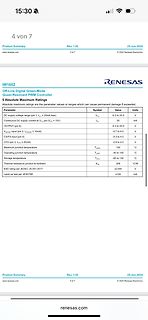
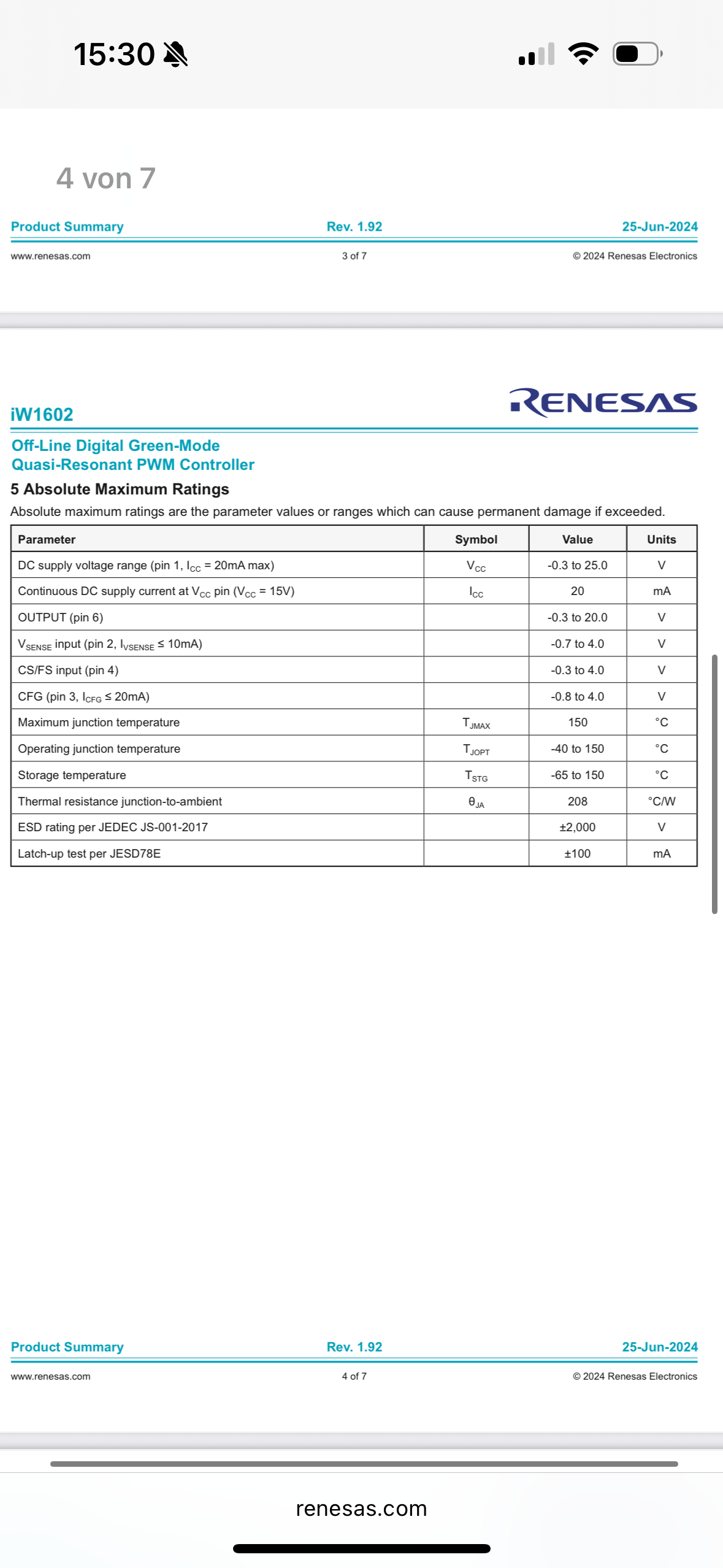
5 Absolute Maximum Ratings
Parameter Symbol Value Units
DC supply voltage range (pin 1, ICC = 20mA max) VCC -0.3 to 25.0 V
Continuous DC supply current at VCC (VCC = 15V) ICC 20 mA
OUTPUT (pin 6) -0.3 to 20.0 V
CS/FS input (pin 4) VSENSE input (pin 2, IISENSE <= 10mA) -0.7 to 4.0 V -0.3 to 4.0 V
CFG
of MAX31865 - RTD to Digital Converter:"); Write(Configuration, 0b11010000); // Enabling Vbias of max31865 value = Read(read_Configuration); // Reading contents of Configuration register to verify communication with max31865 is done properly if (value == 208) { Write(Write_High_Fault_Threshold_MSB, 0xFF); // Writing High Fault Threshold MSB Write(Write_High_Fault_Threshold_LSB, 0xFF); // Writing High Fault Threshold
D L b E1 E e e1 C A1 A2 A SOT23-5 package mechanical data dimensions symbol millimeters inches min max min max A 1.050 1.250 0.041 0.049 A1 0.000 0.100 0.000 0.004 b 0.300 0.500 0.012 0.020 C 0.100 0.200 0.004 0.008 D 2.820 3.020 0.111 0.119 E 1.500 1.700 0.059 0.067 E1 2.650 2.950 0.104 0.116 e 0.950
max Supply Voltage Rejection RatiS =R50) dB SVR T = +25°C 80 86 70 86 amb Tmin≤ Tamb ≤ Tmax 80 70 Supply Current, no load, per amplifier mA CC Tamb= +25°C 1.4 2.5 1.4 2.5 Tmin≤ Tamb ≤T max 2.5 2.5 V icm
max Supply Voltage Rejection RatiS =R50) dB SVR T = +25°C 80 86 70 86 amb Tmin≤ Tamb ≤ Tmax 80 70 Supply Current, no load, per amplifier mA CC Tamb= +25°C 1.4 2.5 1.4 2.5 Tmin≤ Tamb ≤T max 2.5 2.5 V icm
Features and Benefits B120/B, B130/B, B140/B Guard Ring Die Construction for Transient Protection V max (V) T = I (mA) T Ideally Suited for Automated Assembly VRRM (V) O (A) F A R max A +25°C = +25°C Low Power Loss, High Efficiency 20/30/40 1.0 0.5 0.5 Surge Overload Rating to 30A Peak B150/B, B160
ziemlich LUT-fressend dann, ist ja klar. Wieso keinen IP-Core? Die sind sehr effizient gemacht. Die max. 70% Füllgrad sind ein Erfahrungswert meinerseits. Ich hatte bisher bei allen FPGA Designs, die mehr als 70 oder 75% belegen, Schwierigkeiten beim Routing. Erstens mal dauert das dann ewig und zweitens
Learning Board Bread Board Xilinx XC9572XL CPLD Development Board Learning Board Bread Board "Altera MAX II EPM240 CPLD Development Board Learning Board Test Panel" ALTERA FPGA Cyslonell EP2C5T144 Minimum System Learning Board Development "ALTERA EP2C8Q208 FPGA Nios II Minimum System Learning Board
module Eight&digit & serial interface & Red highlight & digital tube display module & 74hc164 dreve MAX7219 lattice module 8 * 8 dot matrix display driver module can be seamlessly MAX7219 4 in 1 dot matrix module 16 x16 dot matrix display driver module MAX7219 9 in 1 dot matrix module 24 x24 dot matrix
Lead–free assembly t P p -Temperature Min (T ) 150°C s(min) Ramp-up CTto Tal Zone Pre Heat -Temperature Max (T ) 200°C L L P s(max) ) L -Time (min to max) (t ) 60 – 180 secs (s(max) s u Average ramp up rate (LiquidusTemp r Ramp-down 3°C/second max ps(min) (TL) to peak m s T Preheat T S(max)T L Ramp-up Rate 3°C/second max -Temperature (T )L(Liquidus) 217°C 25˚C t 25˚C to Peak Reflow -Time (min to max) (t s 60 – 150 seconds Time (t) +0/-5 PeakTemperature (T ) P 260 °C Time within 5°C of actual peak 20 – 40 seconds Temperature
Max S. schrieb im Beitrag #6481058: > Alles, was eine Tretkurbel hat, hat auf der > Straße nicht wirklich was verloren. Fahrräder gibt es schon länger als Autos, also haben wenn schon die Tretkurbel-bewehrten
#6523894: > Die Meisten fahren Pedelec. > Da gibt es keine Brände. Ach! Nur weil beim Pedelec die max. Geschwindigkeit begrenzt ist, brennt der Akku nicht? Was für eine Logik?
ergänzen! Und was auch noch wichtig für das Endprodukt ist ist, dass es mit vollen 4 MHz läuft! Also das max was der 912DG128A Chip kann..... Danke!
Frequenz max: 100 kHz Ampl max: 19 mA... in Volt... ?? Sagen wir 0,5 V! Ja das ist schon klar, dass es langsamer wird... es dürfte dann bis zu 0,5s brauchen ein Sinus... bzw 2 Perioden also 2 Sinuse ;) Danke

 Bild
Bild
 Bild
Bild
 Bild
Bild
 Bild
Bild
 Bild
Bild