-
Datei
ea_dip204-4.c
// file ea-dip204-4.c // IN SERIAL MODE // creator Kees Neele // date 23-02-2014 // tested on PIC18F2550 at 16mHz // MPlabX 1.95 // Hi-Tech pro v9.80 #include <htc.h> #include "ea_dip204-4.h" bit sflag ; // to test for first data sending [startcode] [=1] or for repeating data transfer [=0] void
in „Display DIP204-4“ · Mikrocontroller und Digitale Elektronik ·
-
PDF
MCP794xx.pdf
Power-Fail Timestamp 0x20 SRAM (64 Bytes) 0x5F 0x60 0xEF 0xF0 Protected EEPROM (8 Bytes) Unimplemented; device does not ACK EUI-48/EUI-64 Node Address 0xF7 0xF8 Unimplemented; device does not ACK 0xFF 0xFF I C Address:1101111x I C Address:1010111x
in „MCP794xx EUI-64 Node Adresse“ · Mikrocontroller und Digitale Elektronik ·
-
Datei
Displayinitialisierung_16F877A_abfragen_fix.asm
Byte172 retlw 0xFF ; Byte173 retlw 0xFF ; Byte174 retlw 0xFF ; Byte175 retlw 0xFB ; Byte176 retlw 0xF9 ; Byte177 retlw 0xF8 ; Byte178 retlw 0xF8 ; Byte179 retlw 0x78 ; Byte180 retlw 0x38 ; Byte181 retlw 0x18 ; Byte182 retlw 0x08 ; Byte183 retlw 0x00 ; Byte184 retlw 0x00 ; Byte185 retlw 0x00 ; Byte186
in „[PIC]Probleme bei SPI Übertragung“ · Mikrocontroller und Digitale Elektronik ·
-
Datei
Displayinitialisierung_16F877A_Puffer_Check_fix.asm
Byte172 retlw 0xFF ; Byte173 retlw 0xFF ; Byte174 retlw 0xFF ; Byte175 retlw 0xFB ; Byte176 retlw 0xF9 ; Byte177 retlw 0xF8 ; Byte178 retlw 0xF8 ; Byte179 retlw 0x78 ; Byte180 retlw 0x38 ; Byte181 retlw 0x18 ; Byte182 retlw 0x08 ; Byte183 retlw 0x00 ; Byte184 retlw 0x00 ; Byte185 retlw 0x00 ; Byte186
in „[PIC]Probleme bei SPI Übertragung“ · Mikrocontroller und Digitale Elektronik ·
-
PDF
Under_the_Hood_of_Flyback_SMPS_Designes_slup261__TI.pdf
1-13 Texas Instruments 13 SLUP261 Current Probe VDD 10 I V6 RW3 W6 W3 W6 R6 1 V AW3 (9T) (9T) 6.8 µF i p o Current T Current Transformer Probe V_prim 100:1 W4 V4 36 W4 300 14T ) 6.8 µF R4 +Vi 5 V W1 W2 21T ) (4T) 1:100rent TransforV_I R clamp 0.1 µF – V sec 15 k + +clamp MURS120 IP W2 6.8
in „Flyback-Wandler Störungen auf Versorgung“ · Analoge Elektronik und Schaltungstechnik ·
-
Datei
GlobalDefinitions.h
******************************** * FileName: GlobalDefinitions.h * Dependencies: none * Processor: PIC18F4685 * Complier: Microchip C18 * * * Author Date Comment *~~~~~~~~~~~~~~~~~~~~~~~~~~~~~~~~~~~~~~~~~~~~~~~~~~~~~~~~~~~~~~~~~~~~ * Stephan Krause 17/8/12 Version 1.0 - Initial Release **************
in „Array beschreiben schlägt fehl“ · Mikrocontroller und Digitale Elektronik ·
-
PDF
slyt441.pdf
4700 pF 2 kV To PE Mains PE VS2 ISO VS2 Slave 1 kΩ 0.1 µF 0.1 µF1 kΩ 1 kΩ 0.1 µF Node VS2 DE VCC VCC1 EN1 EN2 VCC2 0.1 µF 100 Ω 1A R F 1R IA OUT A 1B C VCC F CLKIN A0 100 Ω 2A R F IN OUT 2B 2R B B SDI ADC C F 1Y SDO A0 R F OUTC IN GND 1Z 1 C CF 2Y 2D R F OUTD IND 2Z CF RE GND GND1 GND2 1 kΩ 4700 pF SN65C1167 ISO7242C 2 kV To PE Mains PE 18 High-Performance Analog Products www.ti.com/aaj 4Q 2011 Analog Applications
in „SPI über Distanz (3,5m)“ · Mikrocontroller und Digitale Elektronik ·
-
PDF
Stromzange_im_Eigenbau.pdf
this by calibrating to a different read- ing. Just measure the supply voltage, divide the value by 18 (to get the cur- rent)andmultiplyby100toobtainthe calibration number. Forexample,ifyouareusinga13.8V supply, you will have to set VR1 for a reading of 76.7mV on the meter (ie, 13.8/18 × 100 = 76.7).
in „[S] Stromtastkopf bis ca. 100 mA (DC / AC) mit ca. 1 MHz Bandbreite“ · Markt ·
-
Datei
lsg10tx_v2.asm
Bitnummer des Sendeflag outpin Equ 1 ; Ausgabepin Time_H2 Equ 0xFD ; Timer1 Wert: 65536-625 = 64911 (0xFD8F) Time_L2 Equ 0x8F ; ((1MHZ : 8 ) : 625 = 200 Hz (=5ms) ;************************************************************** ; los gehts mit dem Programm org 0 goto Init ;*********************************
in „Leitungssuchgeräte - Funktionsweise / Selbstbau“ · Analoge Elektronik und Schaltungstechnik ·
-
Datei
s65.c
Clustervar; unsigned char Dir_Attrib = 0; unsigned long Size = 0; // Initialisierungssequenzen prog_uint8_t INIT1[24] = { 0xFD, 0xFD, 0xFD, 0xFD, 0xEF, 0x00, 0xEE, 0x04, 0x1B, 0x04, 0xFE, 0xFE, 0xFE, 0xFE, 0xEF, 0x90, 0x4A, 0x04, 0x7F, 0x3F, 0xEE, 0x04, 0x43, 0x06,}; prog_uint8_t INIT2[40] = { 0xEF, 0x90
in „Bausatz Add-on für AVR-NET-IO“ · Mikrocontroller und Digitale Elektronik ·
-
Datei
GenProcs.c
*********************************** * FileName: GenProcs.c * Dependencies: GenProcs.h * Processor: PIC18F4685 * Complier: Microchip C18 * * * Author Date Comment *~~~~~~~~~~~~~~~~~~~~~~~~~~~~~~~~~~~~~~~~~~~~~~~~~~~~~~~~~~~~~~~~~~~~ * Stephan Krause 17/8/12 Version 1.0 - Initial Release **************
in „Array beschreiben schlägt fehl“ · Mikrocontroller und Digitale Elektronik ·
-
Datei
Wie_archiviert_ihr_Websites__-_Mikrocontroller.net.htm
position: absolute; cursor: pointer; display: inline-block; border: 2px solid #AAA; border-radius: 18px; -webkit-border-radius: 18px; -moz-border-radius: 18px; -khtml-border-radius: 18px; font-family: 'Courier New',Courier; font-size: 24px; color: #F0F0F0} .MathJax_MenuClose span {display: block; background-color
-
Datei
MCP795XX.c
/************************************************************************/ // MCP795XX-Routine für PIC18F47Q43 // Programmierer: Fa. Schwabenplan, Ingo Schick // Compiler: XC8 // Datum: 10.06.2024 /************************************************************************/ /****************************
in „RTC -> MCP79521“ · Mikrocontroller und Digitale Elektronik ·
-
PDF
142c38eef4c5eb392531e1bacd4aee1b.pdf
N ( ( ( E 3 2 2 N 4 9 4 V (31.90) ) ) ) R O M E N 2 0 A S . 4 4 0 L e 0 . . 5 ( P D ) 0 0 2 M R 0.18 t P M ( d O S D a n d p l E a t R l e e e C l a G A l l O u I e il B . . . t O 0 A 0 0 ) ) ) i N 1 6 1 e : 8 ) R H V S p e 5 I 0 S e 3.50±0.30 0 f o 2.80±0.15 ± n e 0.20±0.03 1.30±0.15 . r T 1.10±0.15
in „Raspberry Pi Rev A TFT Display?“ · Digitale Signalverarbeitung / DSP / Machine Learning ·
-
Datei
main.c
/* * File: main.c * Author: jossiagee */ #include <pic18f4520.h> #pragma config OSC = INTIO67 //Oszillator #pragma config LVP = OFF //Low Voltage Programming aus #pragma config WDT = OFF //Watchdog Timer aus #define RS PORTEbits.RE1 //Display Register Select
in „LCD Display zeigt keine Zeichen an (PIC18, HD44780)“ · Mikrocontroller und Digitale Elektronik ·
-
Datei
Schalt_Delay.ASM
begonnen: ? ; Version: 0.1 ;*********************************************************** ; Hardware: PIC 16F628 ; Testplatine 18Pin ; 4MHz-Quarz ; 8xLED rot + 8xVorwiderstand 390 Ohm ; Rv = (5V - Uf)/0,01A ; Rv = (5V-1,8V)/0,01 = 320 Ohm, ; nächste Normwerte 330, 390, 470 Ohm ;*************************
in „Achtung: Anfänger! PIC16F628 Fehlermeldung beim Assemblieren“ · Mikrocontroller und Digitale Elektronik ·
-
Datei
Weather_BME680.c
/* Muster Projekt PIC18F46K22 mit externen 4MHz Quarz auf MikroElektronika EasyPIC v7 Belegung: PORTA = PORTB = LCDisplay PORTC = RC4_bit SDI1 --> RC5_bit SDO1 --> SDA RC3_bit SCK1 --> CLock SPI/I2C PORTD = Belegung SDO
in „BME680 Druckberechnung viel zu hoch“ · Mikrocontroller und Digitale Elektronik ·
-
PDF
Hexfiles_in_Tabelle.pdf
RP0 0011 081A MOVF 0x1A,w 000E 1303 BCF STATUS,RP1 0012 1C98 BTFSS 0x18,1 000F 1E8C BTFSS 0x0C,5 0013 2818 GOTO M0018 0010 2827 GOTO M0027 0014 081A MOVF 0x1A,w 0011 081A MOVF 0x1A,w 0015 1218 BCF 0x18,4 0012 1C98 BTFSS 0x18,1 0016 1618 BSF 0x18,4 0013 2818 GOTO M0018 0017
in „Was kann einem PIC16Fxxx das Programm zerschießen?“ · Mikrocontroller und Digitale Elektronik ·
-
Datei
main.c
**************************************************************************************/ #include <p18f4550.h> // Für den PIC - wird autom. erkannt #include "delays.h" // Für die Warteschleife /**********************************************************************************************/ // Konfiguration
in „PIC18F4550 - PIC macht "nix"“ · Mikrocontroller und Digitale Elektronik ·
-
PDF
AmateurfunktagungMuenchen.pdf
Voigt DJ7WI 15:00 - 15:45 Der Mikrowellen-Bereich, ein breites Betätigungsfeld für den Amateurfunk F. Edinger DL5FAU 10:15 - 11:00 Ein neuartiges Konverter-Konzept mit subharmonischen Mischern für 23 cm bis 3 cm F. Schmehr DC8EC 11:15 - 12:00 Amateurfernsehen im 3 cm Band P. Vogel DL8RAH 14:00 - 14:
in „Design einer Hornantenne und Verbindung zum Waveguide“ · HF, Funk und Felder ·
-
PDF
weller_driver_v1_circuit_diagram__1_.pdf
T1OSI/CCP2 RB0/AN12/C2IN1+/INT 22 VREF C 14 RC2/CCP1 RB1/AN10/CXIN3-/OPA2OUT 23 15 RC3/SCK/SCL RB2/AN8/OPA2IN-/DAC3OUT1/CLKR 24 0 0 0 0 0 RC4/SDI/SDA RB3/AN9/CXIN2-/OPA2IN+ REED_PULLUP 3 3 3 3 3 16 RC5/SDO RB4/AN11/C3IN1+ 25 FET_1_DRIVE 17 RC6/TX/CK RB5/AN13/C4IN2-/T1G 26 FET_2_DRIVE 18 RC7/RX/DT/C4OUT VSS 1 2 3 4 5 PIC16F1788-I/SO 8 1 R R R R R 1 C HEATER_2 2 C 3 2 4 6 3 5 0 4 1 2 6 8 4 1 1 1 1 3 5 1 1 7 1 9 TC_2/KTY POTENTIAL 5 1 2 3 4 A C A B C D E F G P A C TC_1 6 I I I I L L D S S HEATER_1 7 D D D D O O O O 7
in „Weller WMRT-MS Micro-Pinzette Inside ?“ · Mechanik, Gehäuse, Werkzeug ·
-
Datei
sms.c
// xxx durch "1 ", "2 ", oder "1+2" ersetzt. #include "C:\programme\cc5\16C84.H" // kompatibel mit PIC16F84 #include <stdio.h> #include "villa.h" #FUSES XT, NOPROTECT #use DELAY(CLOCK=4000000) #use RS232 (Baud=2400, Xmit=PIN_17, Rcv=PIN_18) #BYTE PORT_B=6 int ctrl_z = 26; // Zum Beenden der SMS void
in „C-Code in PIC16F84A“ · Mikrocontroller und Digitale Elektronik ·
-
PDF
Ender3_schematic.PDF
PCO1 PICR PCOR PCO1 PICO1 P2CC 100uF PCR PCO3 PCO3 PRCR P5OC5 PI O1 100uF -for at least the X-stepper Creality changed R6 to 10k P300kPI1R8 P20R7 P0R8 PI100nF P2100nF PC P100kP3R1 P1R0 PRR9 P500nF PI100nF P - according to the TMC2208 datasheet
in „Problem mit SD Card Melzi Creality3D V1.1.3 Sanguino Atmega 1284“ · Mikrocontroller und Digitale Elektronik ·
-
PDF
cc1100.pdf
series 0402 NP0 0402 NP0 pF, 0402 NP0 C122 12 pF ± 5%, 0402 8.2 pF ± 0.5 pF, 1.5 pF ± 0.25 Murata GRM1555C series NP0 0402 NP0 pF, 0402 NP0 C123 6.8 pF ± 0.5 pF, 5.6 pF ± 0.5 pF, 3.3 pF ± 0.25 Murata GRM1555C series 0402 NP0 0402
in „Scrambler für Funkstrecke“ · Mikrocontroller und Digitale Elektronik ·
-
Datei
LED_ein_aus_Taster.asm
runtergeladen und hinzugefügt ;*********************************************************** ; Hardware: PIC 16F628A, Testplatine 18Pin, 4MHz-Quarz, Reset-Taster an RA5, Pullup-Widerstand 10k ; ; PORTB = 8xLED rot + 8xVorwiderstand 4k7 Ohm in Reihe vom Pin gegen Masse ; = High am Pin = LED leuchtet ; ; PORTA
in „Achtung: Anfänger! PIC16F628 Fehlermeldung beim Assemblieren“ · Mikrocontroller und Digitale Elektronik ·
-
PDF
Artikel_Flashboard.PDF
M K RO CO NTR OLLER Edukative Hard- und Software 8 9 S 8 2 5 2 F l a s h - B o a r d Basis für Mikrocontroller-Kurs Von B. Kainka Das Mikrocontroller-Board als Grundlage für einen Programmierkurs modernen Mikrocontrollers mit Peripherie aufweisen. Dies
in „AT89C51AC2 ISP aber wie?“ · Mikrocontroller und Digitale Elektronik ·
-
Datei
DG16080.c
**************************************************************************************/ #include <p18f4550.h> // Headerdatei für den PIC #include "delays.h" // Headerdatei für die Warteschleife /**********************************************************************************************/ // Konfiguration
in „Display mit Touchscreen bei Pollin?“ · Mikrocontroller und Digitale Elektronik ·
-
PDF
TR0166.pdf
Senden der UDP Frames wurde eine bereits fertig erstellte Librar des Vorgangerprojektes verwendet. [Pic06] 2.5. UDP Kommunikation 25 ▯ Quell IP Adresse: 32 Bit IP Adresse des Senders ▯ Ziel IP Adresse: 32 Bit IP Adresse des Empf ngers ▯ Leerfeld: 8 Bit ▯ Protokoll ID: 8 Bit f r UDP zum Beispiel 17 ▯ UDP
in „B&R x2x Link“ · Mikrocontroller und Digitale Elektronik ·
-
PDF
Micrel.pdf
the Minimum Load Current sub-section). VALUES AT FULL LOAD Device Full-Load Capacitor MIC2915x 10 µF MIC2930x 10 µF MIC2950x 10 µF MIC2975x 22 µF 2016-2019 Microchip Technology Inc. DS20005685B-page 25 MIC2915X/30X/50X/75X MIC29152 VIN VOUT R1 10μF 22μF R2 FIGURE 4-2: Adjustable Regulator with Resistors
-
Datei
mac_address.h
/************************************************************************/ // MAC-Adresse für PIC18F9J60 // Programmierer: Fa. Schwabenplan, Ingo Schick // Datum: 29.02.2020 /************************************************************************/ #ifndef MAC_ADDRESS_H #define MAC_ADDRESS_H #include
in „PIC18F97J60 -> MAC Adresse ändern“ · Mikrocontroller und Digitale Elektronik ·
-
PDF
1_AMD_BKDG_Family__15h_Mod_00h-0Fh_BKDG.pdf
D18F1x9C D18F1x18C Range 4 D18F1xA0 D18F1xA4 D18F1x190 Range 5 D18F1xA8 D18F1xAC D18F1x194 Range 6 D18F1xB0 D18F1xB4 D18F1x198 Range 7 D18F1xB8 D18F1xBC D18F1x19C Range 8 D18F1x1A0 D18F1x1A4 D18F1x1C0 291
-
PDF
velleman_hps5_oscilloscope.pdf
D9 R20 AC/DC PMBT2222A +V2 10K T7 EDR301A05 PMBT2222A C10 7 RY2 100n R7 SK3 DGND 47K 1 + BNC C35 T8 AGND OS NULL- C R39 R50 +V6 V +V6 DGND 8 TP3 47n/200V100 100K BAS45AL RV1 22K NC C38 C39 D8 5 1 R28 18p OS NULL+ ANALOGOUT AGND 1n5/200V 3 IN+ - R30 R41 1K C OUT 6 AD IN 39K-1% 8 RY3 14 BAV99 2 IN- V
-
Datei
ADC.txt
#include <18F4680.h> //PIC 18F4680 include Datei einfügen #device adc=8 #use delay(clock=4000000) //Geschwindigkeit des Oszillators #fuses XT,NOWDT //Oszillatoreinstellungen und aussschalten des Watch-Dog-Timers
in „VU Meter mit PIC“ · Mikrocontroller und Digitale Elektronik ·
-
Datei
Nightwing.c
/* * File: Nightwing.c * Author: Karsten * * Created on 19. Oktober 2015, 18:44 */ #include <stdio.h> #include <stdlib.h> #include <p18f23k22.h> // PIC18F23K22 Configuration Bit Settings // 'C' source line config statements #include <xc.h> // #pragma config statements should
in „MCLR funktioniert nicht als Input PIC18F23K22“ · Mikrocontroller und Digitale Elektronik ·
-
Datei
Einschalt_Verz_V2.asm
runtergeladen und hinzugefügt ;*********************************************************** ; Hardware: PIC 16F628 ; Testplatine 18Pin ; 4MHz-Quarz ; 8xLED rot + 8xVorwiderstand 4k7 Ohm ;*********************************************************** ; Aufgabe: LEDs werden nacheinander eingeschaltet und bleiben
in „Achtung: Anfänger! PIC16F628 Fehlermeldung beim Assemblieren“ · Mikrocontroller und Digitale Elektronik ·
-
 Bild
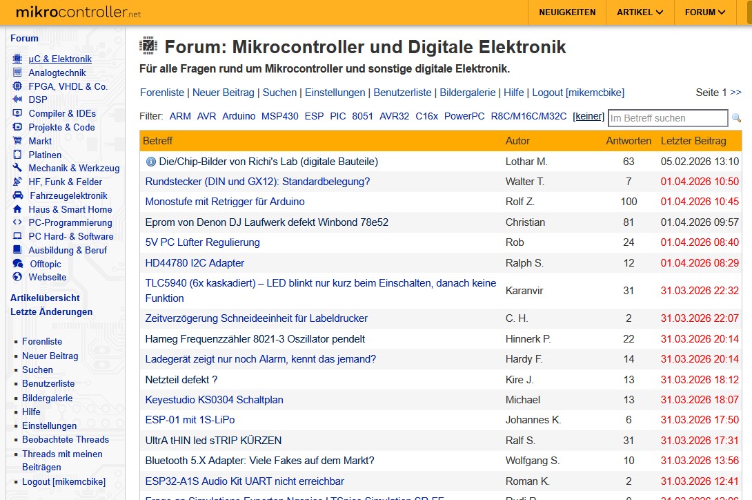
Screenshot eines deutschsprachigen Mikrocontroller-Forums
Einstellungen | Benutzerliste | Bildergalerie | Im Betreff suchen Filter: ARM AVR Arduino MSP430 ESP PIC 8051 AVR32 C16x PowerPC R8C/M16C/M32C [keiner] Betreff Autor Antworten Letzter Beitrag Die/Chip-Bilder von Ric's Lab (dibate Bauteile) Lothar M. 63 05.02.2026 13:10 Rundstecker (DIN und GX12: Standardbelegung
in „Seltsamer Link zu embdev.net“ · www.mikrocontroller.net · · Screenshots
-
Datei
irmp.c
memcpy #else // not unix: #ifdef WIN32 #include <stdio.h> #include <string.h> typedef unsigned char uint8_t; typedef unsigned short uint16_t; #define ANALYZE #define PROGMEM #define memcpy_P memcpy #else #if defined (PIC_CCS_COMPILER) || defined(PIC_C18) #include <string.h> #define PROGMEM #define memcpy_P
in „ATmega resettet dauernd“ · Mikrocontroller und Digitale Elektronik ·
-
Datei
irmp.c
memcpy #else // not unix: #ifdef WIN32 #include <stdio.h> #include <string.h> typedef unsigned char uint8_t; typedef unsigned short uint16_t; #define ANALYZE #define PROGMEM #define memcpy_P memcpy #else #if defined (PIC_CCS_COMPILER) || defined(PIC_C18) #include <string.h> #define PROGMEM #define memcpy_P
in „IRMP - Infrared Multi Protocol Decoder“ · Projekte & Code ·
-
PDF
DCC_Laborbooster.pdf
wird aber nicht abgefangen 71 -Programm säubern/vereinheitlichen und dokumentieren 72 1 'Define für PIC16F1933 2 'jetzt neu für PIC16F1936 (gleich) 3 Define CONFIG1 = 0x0fc2 4 Define CONFIG2 = 0x1dff 5 Define CLOCK_FREQUENCY = 32 'MHz 6 7 Define STRING_MAX_LENGTH = 21 8 9 'DCC-Laborbooster 10 11 'noch
-
PDF
LCD-Steuerung_-_ELV_05522_.pdf
SS/OC1B 16 StiftleistStiftleisStiftleiste wann der Text erscheinen UB + IN OUT 22 GND PB3/MOSI/OC2 18 7-24V 7805 GND PB4/MISO 19 soll. Dies kann, wie be- - GND PB6/XTAL1/TOSC1 9 R17 PB7/XTAL2/TOSC2 10 2K2 T6 reits erwähnt, durch einen 8 ELV05522 BC337-40 C1 + C2 C8 C3 C4 + IC2 C5 einzelnen Eingang oder
-
PDF
MC_product_selection_AN.pdf
microcontroller. a 150 Table 4 summarize the state of the status output during C 100 50 a charge cycle. 0 2 4 6 8 10 12 14 16 18 20 TABLE 4: STATUS OUTPUT Programming Resistor (kΩ) Charge Cycle State MCP73831 FIGURE 4: I vs. R . Shutdown Hi-Z OUT PROG No Battery Present Hi-Z Figure 4 shows the relationship between
in „Hackbarer(?) 21 EUR Quadcopter“ · Mikrocontroller und Digitale Elektronik ·
-
Datei
Servo_Receive_683.asm
LIST P=PIC12F683 INCLUDE P12F683.INC ; CONFIG ; __config 0x3FC4 __CONFIG _FOSC_INTOSCIO & _WDTE_OFF & _PWRTE_ON & _MCLRE_OFF & _CP_OFF & _CPD_OFF & _BOREN_OFF & _IESO_OFF & _FCMEN_OFF errorlevel -302 ;Eliminate
in „Servo Motoren (2 Positionen) mit PIC steuern“ · Mikrocontroller und Digitale Elektronik ·
-
Datei
TelefonPIC16F505.asm
include <p16f505.inc> ; PIC16F505 Configuration Bit Settings ; ASM source line config statements #include "p16F505.inc" ; CONFIG ; __config 0xFFF4 __CONFIG _OSC_IntRC_RB4EN & _WDT_OFF & _CP_OFF & _MCLRE_ON org 0x0000
in „Assembler File für PIC 16F505 in HEX kompilieren mit MPLAB X IDE v4.x“ · Mikrocontroller und Digitale Elektronik ·
-
PDF
DS_BT81X.pdf
9 11 13 15 20 26 34 45 58 68 D 8 8 10 12 14 18 24 9 11 14 17 22 28 36 48 63 69 E 8 7 9 11 13 16 22 7 9 12 13 16 23 29 39 50 70 F 8 6 8 10 12 14 20 7 9 12 13 17 22 29 39 50 71 G 8 8 11 13 15 19 25 9 11 14 16 22 28 37 48 62 72 H 8 8 10
in „STM32F407 DISCOVERY mit EVE3 50GTPC von MatrixOrbital“ · Mikrocontroller und Digitale Elektronik ·
-
Datei
Einschalt_Verz.asm
runtergeladen und hinzugefügt ;*********************************************************** ; Hardware: PIC 16F628 ; Testplatine 18Pin ; 4MHz-Quarz ; 8xLED rot + 8xVorwiderstand 4k7 Ohm ;*********************************************************** ; Aufgabe: LEDs werden nacheinander eingeschaltet und bleiben
in „Achtung: Anfänger! PIC16F628 Fehlermeldung beim Assemblieren“ · Mikrocontroller und Digitale Elektronik ·
-
Datei
zfe_alpha10-test3.asm
=== __MAXRAM H'01FF' __BADRAM H'07'-H'09', H'0D', H'13'-H'14', H'1B'-H'1E' __BADRAM H'87'-H'89', H'8D', H'8F'-H'91', H'93'-H'97', H'9E' __BADRAM H'105', H'107'-H'109', H'10C'-H'11F', H'150'-H'16F' __BADRAM H'185', H'187'-H'189', H'18C'-H'1EF' ;========================================================
in „PIC Taster abfrage“ · Mikrocontroller und Digitale Elektronik ·
-
Datei
blink12F629.asm
DEMO1: SIMPLE RUNNING LIGHT FOR TESTING LD1...LD5 * ;* DEMO1: PROGRAM FOR TESTING K8048/VM111 WITH PIC12F629! * ;************************************************************************** ;* (C) VELLEMAN COMPONENTS,2003 ALL RIGHTS RESERVED * ;**********************************************************
in „PIC 12F 629 ohne *inc -> wo liegt hier der Fehler verborgen?“ · Mikrocontroller und Digitale Elektronik ·
-
PDF
Sensorless_Speed_Controlled_BLDC.pdf
10K U2 TLP721 C8 R8 C7 +15V D3 D4 D5 1 5 1nF 10K 100nF 10BF40 10BF40 10BF40 Q1 Q2 Q3 IRFIZ24G IRFIZ24G IRFIZ24G +5V C9 + TX0 +5V 2 4 R12 R13 10K 22uF R15 R9 R10 R11 10K 10R 10R 10R 10K 5 64 2 3 0 4 5 5 2 2 2 6 3 04 4
in „sensorloser BLDC Motor mit PWM“ · Mikrocontroller und Digitale Elektronik ·