-
Datei
lcd.c
#define DDR(x) (*(&x - 1)) /* address of data direction register of port x */ #if defined(__AVR_ATmega64__) || defined(__AVR_ATmega128__) /* on ATmega64/128 PINF is on port 0x00 and not 0x60 */ #define PIN(x) ( &PORTF==&(x) ? _SFR_IO8(0x00) : (*(&x - 2)) ) #else #define PIN(x) (*(&x - 2)) /* address
in „DCF auf INT0“ · Mikrocontroller und Digitale Elektronik ·
-
Datei
mw_lcd.c
#define DDR(x) (*(&x - 1)) /* address of data direction register of port x */ #if defined(__AVR_ATmega64__) || defined(__AVR_ATmega128__) /* on ATmega64/128 PINF is on port 0x00 and not 0x60 */ #define PIN(x) ( &PORTF==&(x) ? _SFR_IO8(0x00) : (*(&x - 2)) ) #else #define PIN(x) (*(&x - 2)) /* address
in „DCF auf INT0“ · Mikrocontroller und Digitale Elektronik ·
-
Datei
lcd.c
#define DDR(x) (*(&x - 1)) /* address of data direction register of port x */ #if defined(__AVR_ATmega64__) || defined(__AVR_ATmega128__) /* on ATmega64/128 PINF is on port 0x00 and not 0x60 */ #define PIN(x) ( &PORTF==&(x) ? _SFR_IO8(0x00) : (*(&x - 2)) ) #else #define PIN(x) (*(&x - 2)) /* address
in „avr dude Programm zu groß? Eclipse GCC“ · Mikrocontroller und Digitale Elektronik ·
-
Datei
lcd.c
#define DDR(x) (*(&x - 1)) /* address of data direction register of port x */ #if defined(__AVR_ATmega64__) || defined(__AVR_ATmega128__) /* on ATmega64/128 PINF is on port 0x00 and not 0x60 */ #define PIN(x) ( &PORTF==&(x) ? _SFR_IO8(0x00) : (*(&x - 2)) ) #else #define PIN(x) (*(&x - 2)) /* address
in „Probleme mit LCD-Display und SPI Übertragung“ · Mikrocontroller und Digitale Elektronik ·
-
Datei
lcd.c
#define DDR(x) (*(&x - 1)) /* address of data direction register of port x */ #if defined(__AVR_ATmega64__) || defined(__AVR_ATmega128__) /* on ATmega64/128 PINF is on port 0x00 and not 0x60 */ #define PIN(x) ( &PORTF==&(x) ? _SFR_IO8(0x00) : (*(&x - 2)) ) #else #define PIN(x) (*(&x - 2)) /* address
in „LCD-Display Problem“ · Mikrocontroller und Digitale Elektronik ·
-
Datei
lcd.c
#define DDR(x) (*(&x - 1)) /* address of data direction register of port x */ #if defined(__AVR_ATmega64__) || defined(__AVR_ATmega128__) /* on ATmega64/128 PINF is on port 0x00 and not 0x60 */ #define PIN(x) ( &PORTF==&(x) ? _SFR_IO8(0x00) : (*(&x - 2)) ) #else #define PIN(x) (*(&x - 2)) /* address
in „Initialisierung 204b LCD mit ST7066U“ · Mikrocontroller und Digitale Elektronik ·
-
Datei
Fleury_lcd_pollin.c
#define DDR(x) (*(&x - 1)) /* address of data direction register of port x */ #if defined(__AVR_ATmega64__) || defined(__AVR_ATmega128__) /* on ATmega64/128 PINF is on port 0x00 and not 0x60 */ #define PIN(x) ( &PORTF==&(x) ? _SFR_IO8(0x00) : (*(&x - 2)) ) #else #define PIN(x) (*(&x - 2)) /* address
in „LCD HD44780 mit Atmega32 ansteuern“ · Mikrocontroller und Digitale Elektronik ·
-
Datei
lcd_new.c
#define DDR(x) (*(&x - 1)) /* address of data direction register of port x */ #if defined(__AVR_ATmega64__) || defined(__AVR_ATmega128__) /* on ATmega64/128 PINF is on port 0x00 and not 0x60 */ #define PIN(x) ( &PORTF==&(x) ? _SFR_IO8(0x00) : (*(&x - 2)) ) #else #define PIN(x) (*(&x - 2)) /* address
in „HD44780 on Atmega32 with Peter Fleurys library“ · µC & Digital Electronics ·
-
PDF
GCC_Tut_Test.pdf
AVR (z.B. ATmega169, ATmega48/88/168, AT90CAN jedoch nicht fur z.B. AT ega16/32, ATmega128, ATtiny2313) wird durch die Registerde▯nitionen der avr-libc (io*.h) auch fur ontroller mit zwei UBRR-Registern (UBRRL/UBRRH
-
PDF
PWM_Controller_Manual_ohne_EEPROM.pdf
Software PWM Controller ATMEGA 8 Typ: PWM18_V7 (ohne EEPROM) Inhaltsverzeichnis Vorwort ..................................................................................................................................2 Features
in „18- Kanal PWM Controller TWI(IIC)Interface FW. V.3“ · Projekte & Code ·
-
Datei
iom128.h
/* iom128.h - AVR ATmega128 defines Contributors: Created by Peter Jansen <peter@smartcontainer.net> THIS SOFTWARE IS NOT COPYRIGHTED This source code is offered for use in the public domain. You may use, modify
in „AVRGCC und neue Megas?“ · Mikrocontroller und Digitale Elektronik ·
-
Datei
iom128.h
/* iom128.h - AVR ATmega128 defines Contributors: Created by Peter Jansen <peter@smartcontainer.net> THIS SOFTWARE IS NOT COPYRIGHTED This source code is offered for use in the public domain. You may use, modify
in „Problem mit Mega128 USART“ · Mikrocontroller und Digitale Elektronik ·
-
Datei
Cynetik.c
/* */ /* Autor: Constantin Alexandru Mauro */ /* */ /* Zielsystem: Cynetik Mainboard, Prozessor: Atmega8535 */ /* IDE/C-Compiler: AVR Studio 4 */ /* */ /* Letzte Änderung: 01.11.2015 */ /* */ /* Datei: Cynetik.c */ /* */ /*******************************************************************************
in „AD-Wandler im ATmega8535“ · Mikrocontroller und Digitale Elektronik ·
-
Datei
Kondensatormotor-sin_20200327c.ino
int potipluspin = 12; // atmega pin 18 Poti Pluspol int potischleiferpin = A5; // atmega pin 28 Poti Schleifer Über RC-TP int temppin = A4; // atmega pin 27 Temp-Sensor-Tranistor bool temp; int enuppin = 2; // atmega pin 4, Katode Optoled int enunpin = 3; // atmega pin 5, Katode Optoled int enzppin = 4; // atmega pin 6, Katode Optoled int upin = 9; // atmega pin 15, Anode Optoled int zpin = 10; // atmega pin 16, Anode Optoled int enznpin = 7; // atmega pin 13
in „Arduino Kondensatormotor Drehzahlsteuerung“ · Analoge Elektronik und Schaltungstechnik ·
-
Datei
Kondensatormotor-sin_20200331a.ino
int potipluspin = 12; // atmega pin 18 Poti Pluspol int potischleiferpin = A5; // atmega pin 28 Poti Schleifer Über RC-TP int temppin = A4; // atmega pin 27 Temp-Sensor-Tranistor bool temp; int enuppin = 2; // atmega pin 4, Katode Optoled int enunpin = 3; // atmega pin 5, Katode Optoled int enzppin = 4; // atmega pin 6, Katode Optoled int upin = 9; // atmega pin 15, Anode Optoled int zpin = 10; // atmega pin 16, Anode Optoled int enznpin = 7; // atmega pin 13
in „Arduino Kondensatormotor Drehzahlsteuerung“ · Analoge Elektronik und Schaltungstechnik ·
-
Datei
880eed3fe10373c0a5d4ca8d0892cc67.txt
CONFIG_EXPERIMENTAL=y # CONFIG_EXPERT is not set ARCH=ARCH_AVR ARCH_AVR=y # ARCH_HOST is not set # atmega8 is not set # atmega88 is not set # atmega128 is not set # atmega16 is not set # atmega162 is not set # atmega168 is not set # atmega168p is not set # atmega169 is not set MCU=atmega32 atmega32=y # atmega328p is not set # atmega64 is not set # atmega644 is not set # atmega644p is not set # atmega1284p is not set FREQ=16000000 # Arduino_Duemilanove is not set # Fimser is not set # Jackalope is not set
in „Ethersex will nicht so richtig“ · Mikrocontroller und Digitale Elektronik ·
-
 Bild
Bild
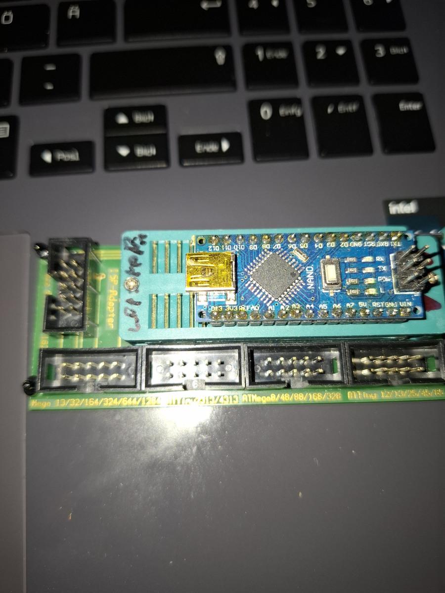
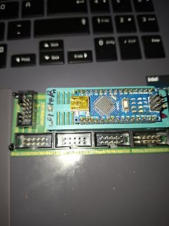
Arduino Nano auf Erweiterungsplatine und Laptop-Tastatur
Arduino Nano, ATmega8, 13/32/164/324/644/128
in „Was für female Verbinder für 2.54mm Pins (serieller Programmier-Adapter)“ · Mechanik, Gehäuse, Werkzeug · · Platinenfotos
-
Datei
DMXmega8.ASM
***** ;* ;* Title : DMX-512 PC-Interface ;* Version : 0.1 ;* Last updated : 26.06.04 ;* Target : ATMega8 ;**** includes **** .include "m8def.inc" ; r2 Aktueller Befehl ; r3 Command Buffer ; r4 DMX-BLOCKSET Pointer Bit 1-8 Bit 0 wird immer als 1 betrachtet ; r5 DMX-BLOCKSET Counter ; r6 Mega8 Calib low
in „Atmel Controller Probleme mit Slot 1 und 2 bei DMX-512“ · Mikrocontroller und Digitale Elektronik ·
-
Datei
main.c
in their definition by a bit-wise inversion of a mask. For example, the FUSE_EESAVE fuse in the ATmega128 is defined as: \code #define FUSE_EESAVE ~_BV(3) \endcode \note The _BV macro creates a bit mask from a bit number. It is then inverted to represent logical values for a fuse memory byte. To combine
in „Tiefentladungsschutz mit Attiny und P-Kanal Fet“ · Mikrocontroller und Digitale Elektronik ·
-
 Bild
Bild
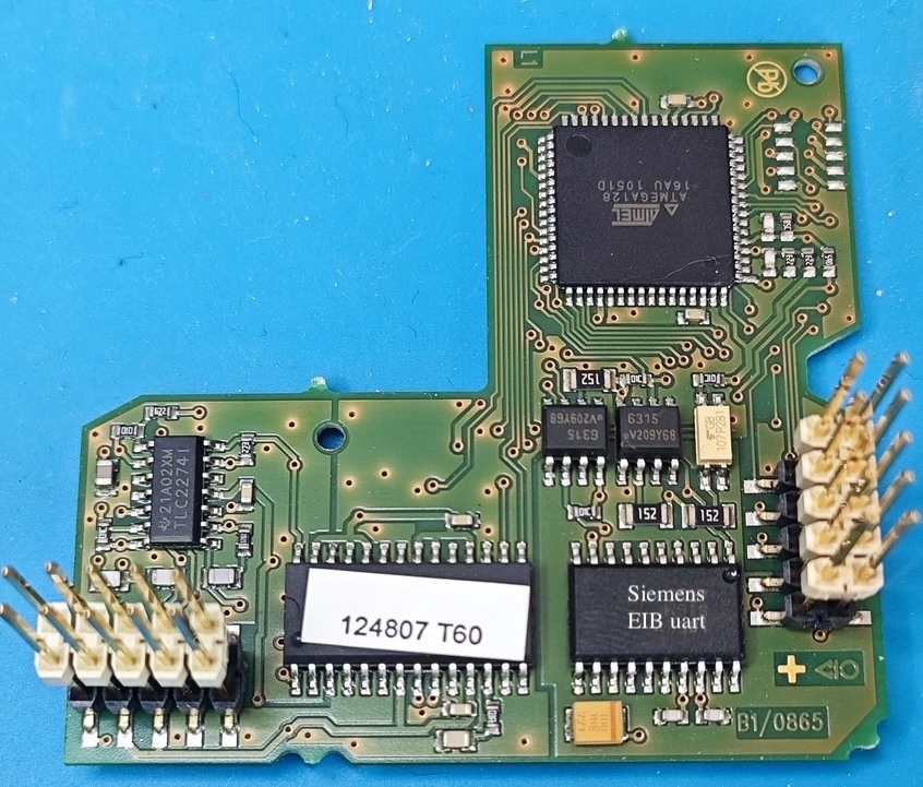
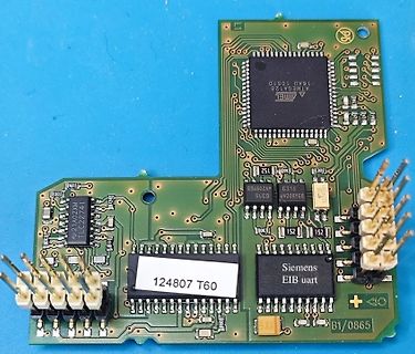
Leiterplatte mit Atmel ATmega und Siemens EIB UART Chip
ATMEL ATmega128 16AU 1051D 21A02XM TLC22741 Siemens EIB uart 124807 T60 B1/0865
in „Spannungsversorgung Busch Jäger 6987/10 Medienkoppler“ · Haus & Smart Home · · Platinenfotos
-
Datei
Programm.c
MUX1) // "-" |(0<<MUX0); // "-" ADCSRA =(1<<ADEN) //ADC Einschalten |(1<<ADPS2) //ADC Takt: F_Quarz/128 |(1<<ADPS1) // "-" |(1<<ADPS0) // "-" |(1<<ADSC); //Starte Conv. while(ADCSRA & (1<<ADSC)); //Dummy Wandlung dummy = ADCW; //Dummy lesen } void init_ADC_Current(void) { unsigned int dummy; ADMUX =(0
in „ADC Auto-Trigger mit Timer1 Compare Match B“ · Mikrocontroller und Digitale Elektronik ·
-
Datei
main.c
====================================================== #include <avr/io.h> // Header-Dateien zum ATmega88 #include <stdbool.h> // Header-Datei fuer Bit-Berechnung #include <avr/interrupt.h> // Header-Datei fuer Interrupts #include <util/delay.h> // Header-Datei fuer Wartezeit #include "lcd_lib_de.h"
in „ADC gibt kein Wert aus“ · Mikrocontroller und Digitale Elektronik ·
-
PDF
Wortuhr_Meilenstein.pdf
; //alle LEDs aus PORTB = 0xff; PORTC = 0xff; PORTD = 0xff; //--------Timer2 Initialisierung für ATMEGA16 Timer Overflow Interrupt----- ASSR |= (1<<AS2); //Timer2 auf asynchronous mode (32,768kHz) TCCR2 |= ((1<<WGM21)|(1<<CS22)|(1<<CS20)); //Vorteiler auf 128 TIMSK |= (1<<TOIE2); //Timer2 Interrupt frei OCR2 = 255; //OCR = (fclk / (2*Prescaler*f_OCN))-1 = ((32768Hz / (2* 128*0.5Hz))-1 = 255 sei (); // globale Interruptfreigabe //------------------Einstellen der Uhrzeit------------------- while(1) { tasten = ~PIND; if (tasten & 0x80) //wenn Taste Stunden an PIND7 gedrückt
in „Programmcode überprüfen“ · Mikrocontroller und Digitale Elektronik ·
-
Datei
adc.c
******************************************************** // File........: adc.c // Target(s)...: ATmega328p // Compiler....: AVR-GCC // Description.: AVR ADC routines //*************************************************************************** //#include <inavr.h> #include <avr/io.h> //#include <avr
in „ADC in C unter WinAVR ärgert“ · Mikrocontroller und Digitale Elektronik ·
-
PDF
Doku_130816.pdf
Länge 256 Bytes, von denen jedoch 3 Byte für den Header benötigt werden. Empfehlung: Datenlänge auf 128 Byte beschränken ! Einschränkungen bei TWI-Read Während einer aktiven Übertragung können bereits neue Jobs im Ringpuffer aufgenommen werden, der Empfang erfolgt Interrupt-gesteuert im Hintergrund. Neue
-
Datei
ODM100.c
* ******************************************************************************** * Processor : ATmega32 @ 8 MHz * Compiler : IAR (V4.30D) & GCC (WinAVR Version 10-01-2010) * Dot Matrix : 128 RGB x 128 * Driver IC : SSD1351 (Solomon Systech) * Interface : 8-bit 8080 Parallel ************************
in „Frage zum ODM100 OLED Bausatz von ELV“ · Mikrocontroller und Digitale Elektronik ·
-
Datei
oled1.c
* ******************************************************************************** * Processor : ATmega32 @ 8 MHz * Compiler : IAR (V4.30D) & GCC (WinAVR Version 10-01-2010) * Dot Matrix : 128 RGB x 128 * Driver IC : SSD1351 (Solomon Systech) * Interface : 8-bit 8080 Parallel ************************
in „AVR Oled Display odm 100-Wie ansteuern?“ · Mikrocontroller und Digitale Elektronik ·
-
Datei
oled.c
* ******************************************************************************** * Processor : ATmega32 @ 8 MHz * Compiler : IAR (V4.30D) & GCC (WinAVR Version 10-01-2010) * Dot Matrix : 128 RGB x 128 * Driver IC : SSD1351 (Solomon Systech) * Interface : 8-bit 8080 Parallel ************************
in „ODM100 OLED bleibt schwarz“ · Mikrocontroller und Digitale Elektronik ·
-
Datei
ODM100.c
* ******************************************************************************** * Processor : ATmega32 @ 8 MHz * Compiler : IAR (V4.30D) & GCC (WinAVR Version 10-01-2010) * Dot Matrix : 128 RGB x 128 * Driver IC : SSD1351 (Solomon Systech) * Interface : 8-bit 8080 Parallel ************************
in „SSD 1351 - OLED ansteuern“ · Mikrocontroller und Digitale Elektronik ·
-
 Bild
Bild
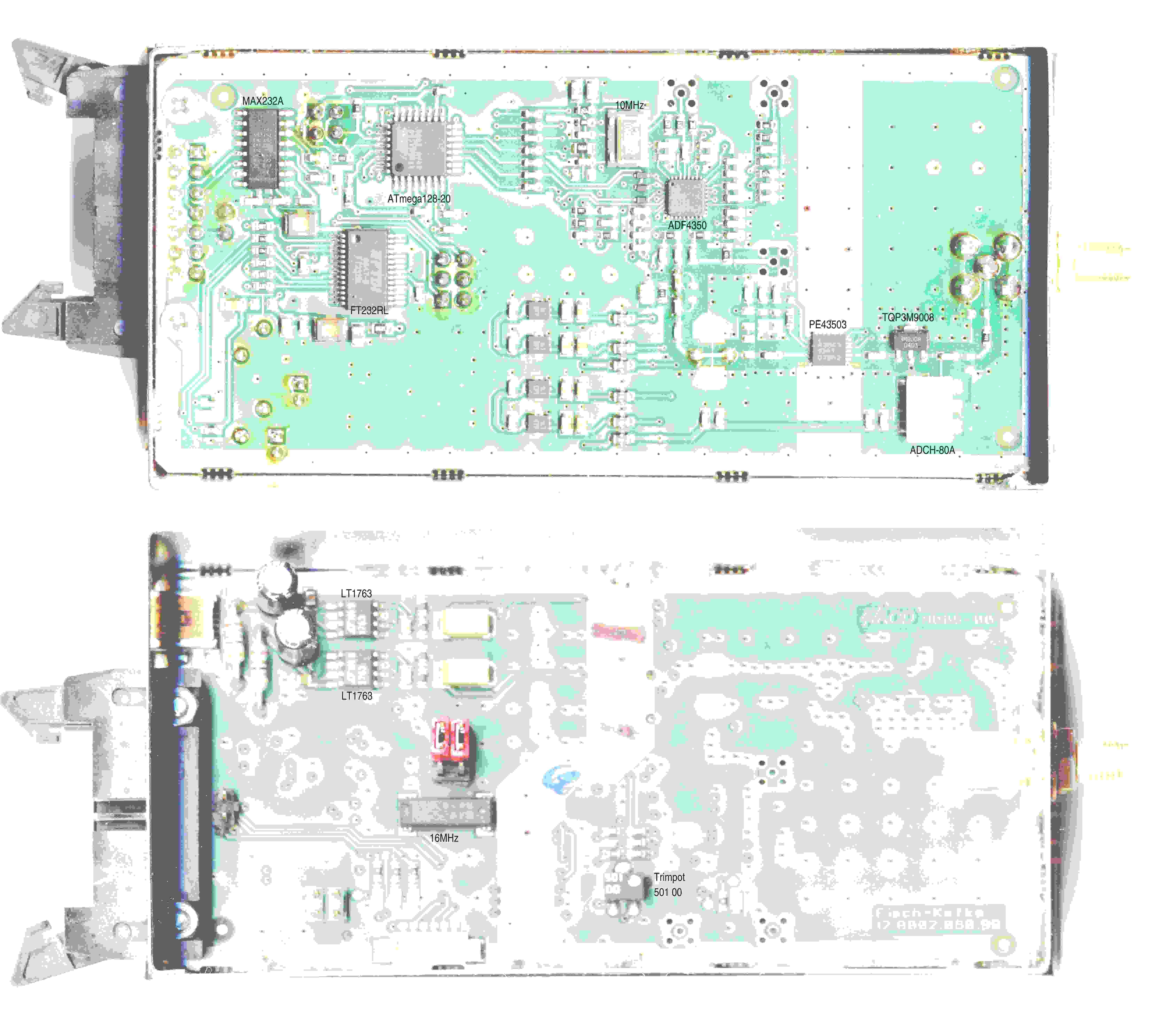
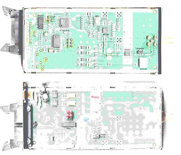
Vorder- und Rückseite einer Leiterplatte
MAX232A ATmega128D 10MHz ADF4569 PE43503 TQ9A9608 ADCH-80A LT1763 16MHz Trimpot 501 00 Fisch-Kefk 12 AB02 858 99
in „ADF4350-Modul SIG01 Eisch-Kafka Ulm“ · HF, Funk und Felder · · Platinenfotos
-
Datei
hardcopy.c
0; // Breite des Bitmaps (Byte 3) } if (hardcopy.ucRahmen == 0) { Schnittstelle.ucData_tx[22-13] = 128; // Höhe des Bitmaps (Byte 0) Schnittstelle.ucData_tx[23-13] = 0; // Höhe des Bitmaps (Byte 1) Schnittstelle.ucData_tx[24-13] = 0; // Höhe des Bitmaps (Byte 2) Schnittstelle.ucData_tx[25-13] = 0; //
in „G16-Format: Wandlung in BMP?“ · Mikrocontroller und Digitale Elektronik ·
-
Datei
uart3.c
MUST call this function BEFORE using UART3) void initUART3(void) // UART3 = software UART { //RX // ATmega8 // ATmega128 PORTD |= ((1) << PIN0); // PORTD.0 = 1; // pull-up DDRD &=~((0) << PIN0); // DDRD.0 = 0; // input //TX PORTD |= ((1) << PIN4); // PORTD.4 = 1; // logic 1 (high level = STOP TX) DDRD |
in „ATmega8 und Dynamixel AX-12+“ · Mikrocontroller und Digitale Elektronik ·
-
Datei
DC_Motor_Regler.c
Drehzahlregelung eines 12V DC-Motors mit Steuerspannung (Poti). Nachfolgendes Programm ist auf einem ATmega328 getestet; ein ATtiny13 wuerde aber schon reichen. Die Schaltungsbeschreibung, mit der man ggf. auch ohne Schaltplan auskommt: Ein AVR-Controller bekommt seine Versorgungsspannung von einem 5V-Regler
in „Drehzahlregler für DC-Motor, ATmega48-328“ · Projekte & Code ·
-
PDF
Inline_AVR8ASM_arduino.pdf
festgestellt werden, um welchen Port des µC es sich handelt. PIN 13 des Uno-Boards ist direkt mit PB5 des ATmega 328P verbunden, gehört also zum Port B des µC [Atmel Datenblatt 2009, Figure 2-1, S.5]. Alle Porteinstellungen sind in 8bit-Registern (8-bit Architektur, bit 0 bis 7) organisiert [Atmel Datenblatt
in „Mit dem ATMEL STUDIO 7 klarkommen“ · Mikrocontroller und Digitale Elektronik ·
-
PDF
assembler_arduino.pdf
festgestellt werden, um welchen Port des µC es sich handelt. PIN 13 des Uno-Boards ist direkt mit PB5 des ATmega 328P verbunden, gehört also zum Port B des µC [Atmel Datenblatt 2009, Figure 2-1, S.5]. Alle Porteinstellungen sind in 8bit-Registern (8-bit Architektur, bit 0 bis 7) organisiert [Atmel Datenblatt
in „Arduino Timerprobleme - suche programmierbaren Oszillator“ · Mikrocontroller und Digitale Elektronik ·
-
Datei
MD_NMRA_DCC.h
combi) and direct mode. You can also read cv's! EXAMPLE HERE FOR: 2F outputs 2Switches Brake module ATMEGA168 */ //FIRST: /* 1. Change the 8 defines if not ok 2. Check dcc_init and change if not ok 3. cv_specific_decoder_values_t make your implementation 4. _decoder make additional bit fields (in front
in „FULL NMRA DCC Library, Encoder, Generator, Bremsmodul“ · Projekte & Code ·
-
PDF
AVR911.pdf
h Help information (overrides all other settings). -? Same as –h Some examples follows: avrosp –dATmega128 –pf –vf –ifprogram.hex –e The above example will first erase the entire memory contents and then program and verify the data contained in program.hex to an attached Atmega128 device. avrosp –dATmega32 –re –oedump.hex –ae0,ff –cCOM2 The above example will read the first 256 bytes of the Atmega32’s EEPROM memory to the file dump.hex. Only COM2 will be used. avrosp –dATmega64 –O#a0 –Se0 –lc0 4 AVR911 2568A-AVR-07/04 AVR911 The above example will write the custom oscillator calibration value
in „AVR911: Das Ende aller Leiden?“ · Mikrocontroller und Digitale Elektronik ·
-
Datei
AVR8_Burn_O_Mat_Config.xml
caption="4.0V (3.7V - 4.5V)" Fuse1="0" Fuse2="0"/> </BrownOutDetection> <OscillatorOptions Type="ATmega8" /> </AVR> <AVR name="m16" caption="ATmega16"> <Fuse name="OCDEN" bit="7" fuseByte="hfuse" default="1" desc="Enable OCD (on chip debug)" mode="expert"/> <Fuse name="JTAGEN" bit="6" fuseByte="hfuse
-
Datei
cynetik.c
/* */ /* Autor: Constantin Alexandru Mauro */ /* */ /* Zielsystem: Cynetik Mainboard, Prozessor: Atmega8535 */ /* IDE/C-Compiler: AVR Studio 4 */ /* */ /* Letzte Änderung: 01.11.2015 */ /* */ /* Datei: Cynetik.c */ /* */ /*******************************************************************************
in „VMLAB: Interrupt-Funktion vom Timer wird nicht aufgerufen“ · Mikrocontroller und Digitale Elektronik ·
-
Datei
cynetik.c
/* */ /* Autor: Constantin Alexandru Mauro */ /* */ /* Zielsystem: Cynetik Mainboard, Prozessor: Atmega8535 */ /* IDE/C-Compiler: AVR Studio 4 */ /* */ /* Letzte Änderung: 01.11.2015 */ /* */ /* Datei: Cynetik.c */ /* */ /*******************************************************************************
in „VMLAB: 40 kHz wird nicht erreicht und alle anderen Funktionen werden übersprungen“ · Mikrocontroller und Digitale Elektronik ·
-
Datei
temp.txt
// CPU ist eine ATMega 128 #include <avr\io.h> //Einfügen der Headerdatei für die Namen der AVR Register usw. #include <stdint.h> //Weis noch nicht wo für //Deklaration der verwendeteten Funktionen im Programm int main(void
in „ISP haut nicht hin“ · Mikrocontroller und Digitale Elektronik ·
-
Datei
AVR8_Burn_O_Mat_Config.xml
caption="4.0V (3.7V - 4.5V)" Fuse1="0" Fuse2="0"/> </BrownOutDetection> <OscillatorOptions Type="ATmega8" /> </AVR> <AVR name="m16" caption="ATmega16"> <Fuse name="OCDEN" bit="7" fuseByte="hfuse" default="1" desc="Enable OCD (on chip debug)" mode="expert"/> <Fuse name="JTAGEN" bit="6" fuseByte="hfuse
in „Fehler beim Brennen von ATMEGA48 mit AVRDUDE“ · Mikrocontroller und Digitale Elektronik ·
-
 Bild
Bild
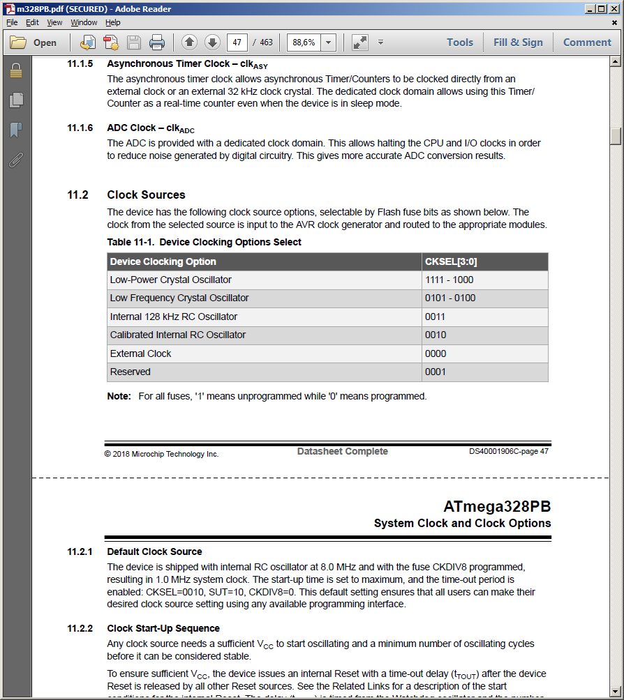
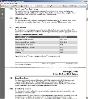
Ausschnitt aus einem ATmega328PB Datenblatt
Low-Power Crystal Oscillator | 1111 - 1000 Low Frequency Crystal Oscillator | 0101 - 0100 Internal 128 kHz RC Oscillator | 0011 Calibrated Internal RC Oscillator | 0010 External Clock | 0000 Reserved | 0001 ATmega328PB System Clock and Clock Options
in „ATMega328PB lässt sich nur noch programmieren. Sonst keine Funktion mehr“ · Mikrocontroller und Digitale Elektronik · · Screenshots
-
PDF
Blockschaltbild.pdf
SD-Card SPI SIO A RTC | IO | A/D I2C UART CRT USB/Seriell Soft I2C SIO B A0..A16 A0..A16 A0..A16 Atmega 1284 Z8S180 128k-512k Z80 - Adressbus
in „CP/M auf ATmega88“ · Mikrocontroller und Digitale Elektronik ·
-
Datei
lcd.c
#define DDR(x) (*(&x - 1)) /* address of data direction register of port x */ #if defined(__AVR_ATmega64__) || defined(__AVR_ATmega128__) /* on ATmega64/128 PINF is on port 0x00 and not 0x60 */ #define PIN(x) ( &PORTF==&(x) ? _SFR_IO8(0x00) : (*(&x - 2)) ) #else #define PIN(x) (*(&x - 2)) /* address
in „ATMega16 PORTA defekt?“ · Mikrocontroller und Digitale Elektronik ·
-
Datei
lcd.c
#define DDR(x) (*(&x - 1)) /* address of data direction register of port x */ #if defined(__AVR_ATmega64__) || defined(__AVR_ATmega128__) /* on ATmega64/128 PINF is on port 0x00 and not 0x60 */ #define PIN(x) ( &PORTF==&(x) ? _SFR_IO8(0x00) : (*(&x - 2)) ) #else #define PIN(x) (*(&x - 2)) /* address
in „Display Programmierung mit GCC 16x4 Display“ · Mikrocontroller und Digitale Elektronik ·
-
Datei
sertest.c
#define __AVR_ATmega128__ 1 #include <avr/io.h> #include <avr/interrupt.h> #include <avr/signal.h> #include <stdio.h> int main(void) { UBRR0H = 0; UBRR0L = 103; /*Divisor fuer 9600 Baud @ 16Mhz */ UCSR0B = (1<<RXEN0) |
in „ATMEGA128 und serieller Port“ · Mikrocontroller und Digitale Elektronik ·
-
Datei
Firmware_v1.2.c
DMX512 reception library * Version : v1.3 * Last updated : 13.04.09 * Target : Transceiver Rev.3.01 [ATmega8515] * Clock : 8MHz, 16MHz * * written by hendrik hoelscher, www.hoelscher-hi.de *************************************************************************** This program is free software; you can redistribute
in „DMX steuerbaren RGB LED PAR oder Pinnspot selber bauen“ · Mikrocontroller und Digitale Elektronik ·
-
Datei
Firmware_v1.2.c
DMX512 reception library * Version : v1.3 * Last updated : 13.04.09 * Target : Transceiver Rev.3.01 [ATmega8515] * Clock : 8MHz, 16MHz * * written by hendrik hoelscher, www.hoelscher-hi.de *************************************************************************** This program is free software; you can redistribute
in „DMX steuerbaren RGB LED PAR oder Pinnspot selber bauen“ · Mikrocontroller und Digitale Elektronik ·
-
PDF
Hausbus_for_everyone.pdf
mehr als 32 Clients benötigt werden kann man die Übertragungsgeschwindigkeit herabsetzen und bis zu 128 Clients dranhängen, oder man nimmt einen uC mit zwei UART’s und baut eine Bridge. BUS Protokoll Ein einfaches selbstprogrammiertes Kommunikationsprotokoll würde voll und ganz ausreichen. Protokoll Paket