-
Datei
gfx_pictures.c
*const pal) { #define pcx(nr) ( readarray(image,nr) ) #define pcxw(nr) ( readwarray(image,nr) ) int32_t pos, c, w, h, e, pack; int32_t c2; uint16_t f; if ((pcx(0) != 10) | (pcx(3) != 8)) // Identity Bytes abfragen { // "Datei ist ein nicht darstellbares Format !!" return; // Function mit Fehlercode beenden
-
Datei
gfx_pictures.c
*const pal) { #define pcx(nr) ( readarray(image,nr) ) #define pcxw(nr) ( readwarray(image,nr) ) int32_t pos, c, w, h, e, pack; int32_t c2; uint16_t f; if ((pcx(0) != 10) | (pcx(3) != 8)) // Identity Bytes abfragen { // "Datei ist ein nicht darstellbares Format !!" return; // Function mit Fehlercode beenden
-
 Bild
Bild
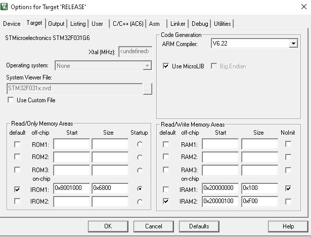
Einstellungen für STM32F031G6 Target Release
Options for Target 'RELEASE' Device Target Output Listing User C/C++ (AC6) Asm Linker Debug Utilities STMmicroelectronics STM32F031G6 Code Generation ARM Compiler V6.22 Xtal (MHz): <undefined> Use MicroLIB Big Endian Operating system: None System Viewer File: None STM32F031x.svd Use Custom File Read/Write Memory Areas default off-chip Start Size Nolnit ROM1: ROM2: ROM3: IROM1: 0x8001000 0x6800 IROM2: RAM1: RAM2: RAM3: IRAM1: 0x20000000 0x100 IRAM2: 0x20000100
in „Keil Clock Frequenz Feld nicht editierbar“ · Mikrocontroller und Digitale Elektronik · · Screenshots
-
Datei
stm32_flash.ld
/* ***************************************************************************** ** ** File : stm32_flash.ld ** ** Abstract : Linker script for STM32F103VB Device with ** 128KByte FLASH, 20KByte RAM ** ** Set heap size, stack size and stack location according ** to application requirements. ** ** Set memory bank area and size if external memory is used. ** ** Target : STMicroelectronics STM32 ** ** Environment : Atollic TrueSTUDIO(R) ** ** Distribution: The file is distributed �as is,� without any warranty ** of any kind. ** ** (c)Copyright Atollic AB. ** You may use this file as-is or
in „GNUARM TChain Linker Problem STM32“ · Mikrocontroller und Digitale Elektronik ·
-
Datei
STM32F334K8_FLASH.ld
/* ***************************************************************************** ** ** File : stm32_flash.ld ** ** Abstract : Linker script for STM32F334K8 Device with ** 64KByte FLASH, 12KByte RAM ** ** Set heap size, stack size and stack location according ** to application requirements. ** ** Set memory bank area and size if external memory is used. ** ** Target : STMicroelectronics STM32 ** ** Environment : Atollic TrueSTUDIO(R) ** ** Distribution: The file is distributed as is, without any warranty ** of any kind. ** ** (c)Copyright Atollic AB. ** You may use this file as-is or modify
in „CCMRAM richtig einsetzen“ · Mikrocontroller und Digitale Elektronik ·
-
Datei
main.c
#include "stm32f4xx.h" ///* Clock Ports */// void StartClock() { RCC_AHB1PeriphClockCmd(RCC_AHB1Periph_GPIOD | RCC_AHB1Periph_GPIOA | RCC_AHB1Periph_GPIOC, ENABLE); } ///* Port Configuration */// void PortConfig(
in „Datenerfassung, Analog -> USB / RS232“ · Mikrocontroller und Digitale Elektronik ·
-
Datei
stm32f10x_can.c
/******************** (C) COPYRIGHT 2007 STMicroelectronics ******************** * File Name : stm32f10x_can.c * Author : MCD Application Team * Version : V1.0 * Date : 10/08/2007 * Description : This file provides all the CAN
in „STM32F10x Cortex M3 CAN Konfiguration“ · Mikrocontroller und Digitale Elektronik ·
-
Datei
STM32F429ZI_FLASH.ld
/* ***************************************************************************** ** ** File : stm32_flash.ld ** ** Abstract : Linker script for STM32F429ZI Device with ** 2048KByte FLASH, 192KByte RAM ** ** Set heap size, stack size and stack location according ** to application requirements. ** ** Set memory bank area and size if external memory is used. ** ** Target : STMicroelectronics STM32 ** ** Environment : Atollic TrueSTUDIO(R) ** ** Distribution: The file is distributed as is, without any warranty ** of any kind. ** ** (c)Copyright Atollic AB. ** You may use this file as-is or modify
in „CCMRAM richtig einsetzen“ · Mikrocontroller und Digitale Elektronik ·
-
Datei
usart.h
USART_TEMPLATE_ARGS void USART_TEMPLATE_QUALIFIER::EnableInterrupt(InterrupFlags interruptFlags) { uint32_t cr1Mask = 0; uint32_t cr2Mask = 0; uint32_t cr3Mask = 0; if (interruptFlags & ParityErrorInt) cr1Mask |= USART_CR1_PEIE; STATIC_ASSERT( USART_CR1_TXEIE == USART_SR_TXE && USART_CR1_TCIE == USART_SR_TC
in „STM32 / C++: Initialisierung von Memberobjekten einer Klasse“ · Mikrocontroller und Digitale Elektronik ·
-
Datei
STM32F746ZGTX_RAM.ld
********************************************** * @file LinkerScript.ld * @author Auto-generated by STM32CubeIDE * Abstract : Linker script for NUCLEO-F746ZG Board embedding STM32F746ZGTx Device from stm32f7 series * 1024Kbytes FLASH * 320Kbytes RAM * * Set heap size, stack size and stack location according
in „Startup code für STM32 C und C++ mix.“ · Mikrocontroller und Digitale Elektronik ·
-
Datei
STM32F746ZGTX_FLASH.ld
********************************************** * @file LinkerScript.ld * @author Auto-generated by STM32CubeIDE * Abstract : Linker script for NUCLEO-F746ZG Board embedding STM32F746ZGTx Device from stm32f7 series * 1024Kbytes FLASH * 320Kbytes RAM * * Set heap size, stack size and stack location according
in „Startup code für STM32 C und C++ mix.“ · Mikrocontroller und Digitale Elektronik ·
-
 Bild
Bild
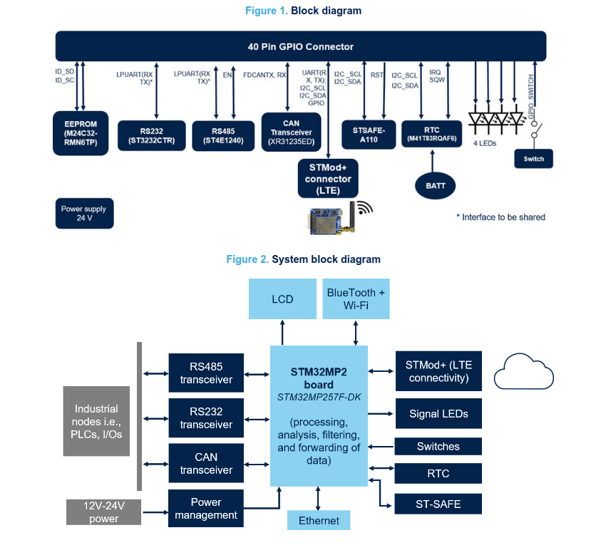
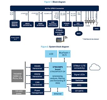
Blockschaltbilder eines GPIO-Connectors und eines STM32MP2 Systems
Block diagram 40 Pin GPIO Connector ID_SD, ID_SC, LPUART(RX TX)*, LPUART(RX TX)*, EN, FDCANTX, RX, UART0, X, TX, I2C_SCL, I2C_SDA, RST, I2C_SCL, I2C_SDA, IRQ, SQW, SWITCH EEPROM (M24C32-RMNSTP), RS232 (ST3232CTR), RS485 (ST4E1240), CAN Transceiver (XR31235ED), STSAFE-A110, RTC (M41T83ROAF6), 4 LEDs, BATT
in „Neue Bauteile: Passives, Spannungsmanagement und MPUs“ · Mikrocontroller und Digitale Elektronik · · Diagramme
-
Datei
eeprom.c
-- */ /* ---------------- System Include Files -------------------- */ #include "stm32f10x_conf.h" #include "system_stm32f10x.h" /* ----------------- C Standard Include Files --------------- */ #include <stdbool.h> #include <stdint.h> #include <stdio.h> #include <stdlib.h> #include
in „STM32F103: EEPROM Abstürze abfangen“ · Mikrocontroller und Digitale Elektronik ·
-
Datei
stm32f407vet6_flash.ld
/* ***************************************************************************** ** ** File : stm32_flash.ld ** ** Abstract : Linker script for STM32F407VG Device with ** 1024KByte FLASH, 192KByte RAM ** ** Set heap size, stack size and stack location according ** to application requirements. ** ** Set memory bank area and size if external memory is used. ** ** Target : STMicroelectronics STM32 ** ** Environment : Atollic TrueSTUDIO(R) ** ** Distribution: The file is distributed as is, without any warranty ** of any kind. ** ** (c)Copyright Atollic AB. ** You may use this file as-is or modify
in „Merkwürdiges Verhalten mit Jlink“ · Mikrocontroller und Digitale Elektronik ·
-
Datei
usb.c
/* ST STM32F103C8T6: USB als COM Port betreiben */ #include "StdTypes.h" #include "STM32F103all.h" #include "usb.h" /* die Transfer-Puffer für zeichenweises In und Out über den USB */ #define txLen 256 char UsbTxBuf
in „USB CDC von Stefan Frings und WS“ · Mikrocontroller und Digitale Elektronik ·
-
Datei
controller.c
#include "stm32f10x_conf.h" #include <stm32f10x_lib.h> ErrorStatus HSEStartUpStatus; void RCC_Configuration(void); //Configures Clock for all devices and GPIOs void NVIC_Configuration(void); void GPIO_init(void);
in „STMF32, SPI, Master, Vollduplex“ · Mikrocontroller und Digitale Elektronik ·
-
PDF
STM32_ADC_modes_and_their_applications.pdf
AN3116 Application note STM32™’s ADC modes and their applications Introduction STM32 microcontrollers have one of the most advanced ADCs on the microcontroller market. You could imagine a multitude of applications based on the
in „STM32F103: Auswahl des richtigen ADC Modus“ · Mikrocontroller und Digitale Elektronik ·
-
Datei
eeprom.c
-- */ /* ---------------- System Include Files -------------------- */ #include "stm32f10x_conf.h" #include "system_stm32f10x.h" /* ----------------- C Standard Include Files --------------- */ #include <stdbool.h> #include <stdint.h> #include <stdio.h> #include <stdlib.h> #include
in „Lebensdauer von lokalen Variablen“ · Softwareentwicklung ·
-
Datei
sysinit.c
uint32_t*)(32 * (((uint32_t)addr) - 0x20000000) + 0x22000000 + 4 * bit)) = val; } /* Bitbanding Teste ein Bit. Rückgabe: Bit */ uint8_t test_bit(uint32_t* addr, const int bit) { return *((volatile uint32_t*)(32 * (((uint32_t)addr) - 0x20000000) + 0x22000000 + 4 * bit)); }
in „Timer Interrupt STM32F103“ · Mikrocontroller und Digitale Elektronik ·
-
Datei
error.txt
Rebuild target 'Target 1' compiling main.c... compiling system_stm32f4xx.c... assembling startup_stm32f40xx.s... linking... c:/armgnu/4.9 2014q4/bin/../lib/gcc/arm-none-eabi/4.9.3/../../../../arm-none-eabi/lib/armv7e-m\libc.a(lib_a-exit.o): In function `exit': exit.c:(.text.exit+0x16): undefined reference to `_exit' collect2.exe: error: ld returned 1 exit status ".\blinky.elf" - 1 Error(s), 0 Warning(s). Target not created. Build Time Elapsed: 00:00:00
in „Keil free für STM32F0“ · Mikrocontroller und Digitale Elektronik ·
-
Datei
WS2812Ctrl.cpp
------------- Resources ----------------------------------------------------------------------- * µC: STM32F103C8 - GPIO: A0 - Timer: TIM2 - DMA: DMA1 Channel 2 - IRQ: DMA1_Channel2_IRQHandler ----------------------------------------------------------------------- Revision History ------------------
-
PDF
schematics.pdf
IRSMMPIU103 PA7 PB7 PIU059 P OHALL2 L2 PI0 P22 PI101 VDDA VSSA PI1012 P H3 H 3 PIU101 PA8 PB8 PIU061 P OCAN_RXRX P1 P1 PI0 STM32F405RGT6 P H2 H 2 PIU102 PA9 PB9 PIU062 P OCAN_TXTX C15 CO35 CO31 P H1 H 1 PIU103 PIU029 RSM P1 2.2µF P22.2µF PI02.2µF
in „BLDC Motorcontroller 200A 48V basierend auf VESC“ · Analoge Elektronik und Schaltungstechnik ·
-
Datei
main.c
// // This file is part of the GNU ARM Eclipse distribution. // Copyright (c) 2014 Liviu Ionescu. // // ---------------------------------------------------------------------------- #include <stdio.h> #include "stm32f10x.h" #include "stm32f10x_conf.h" #include "stm32f10x_tim.h
in „STM32 - Eclipse, ARM GCC - Funktionsaufruf geht nicht :-(“ · Mikrocontroller und Digitale Elektronik ·
-
Datei
mmc_stm32f1.c
/*------------------------------------------------------------------------*/ /* STM32F100: MMCv3/SDv1/SDv2 (SPI mode) control module */ /*------------------------------------------------------------------------*/ /* / Copyright (C) 2014, ChaN, all right reserved. / / * This software
in „STM32F103: Problem mit ChanFat und SD karte“ · Mikrocontroller und Digitale Elektronik ·
-
Datei
sections.ld
/* * Default linker script for STM32Fxxx. */ /* * The '__stack' definition is required by crt0, do not remove it. */ __stack = ORIGIN(RAM) + LENGTH(RAM); _estack = __stack; /* STM specific definition */ /* * Default stack sizes. * These
in „STM32 - Eclipse - GCC - Sind Interruptadressen in Startup definiert?“ · Mikrocontroller und Digitale Elektronik ·
-
Datei
stm32_ub_spi1.c
//-------------------------------------------------------------- // File : stm32_ub_spi1.c // Datum : 29.10.2013 // Version : 1.1 // Autor : UB // EMail : mc-4u(@)t-online.de // Web : www.mikrocontroller-4u.de // CPU : STM32F429 // IDE : CooCox CoIDE 1.7.4 // GCC : 4.7 2012q4
in „STM32F429 - kein Takt am SPI“ · Mikrocontroller und Digitale Elektronik ·
-
Datei
README.TXT
Dieses Programm lässt die LED an PC13 blinken und testet, ob der Chip ein originaler STM32F103C8C6 ist. Hochladen z.B. seriell mit dem Kommando stm32flash -w Blinky_Test-v0.21.bin /dev/ttyUSB2 Die Ausgabe findet seriell mit 115200 Baud statt. Beispiel für ein Original: [08:09:02:129] **
in „Interrupt verhalten bei STM32F103“ · Mikrocontroller und Digitale Elektronik ·
-
Datei
tools.c
_t)(MAX7219_SHUTDOWN << 8) + 1); CE_HIGH(); } /* Matrix löschen */ ClearMatrix(0); } /* Bitbanding: Setzt ein Bit einer Variablen */ void set_bit(uint32_t* addr, const int bit, _Bool val) { *((volatile uint32_t*)(32 * (((uint32_t)addr) - 0x20000000) + 0x22000000 + 4 * bit)) = val; } /* Bitbanding Teste ein Bit. Rückgabe: Bit */ uint8_t test_bit(uint32_t* addr, const int bit) { return *((volatile uint32_t*)(32 * (((uint32_t)addr) - 0x20000000) + 0x22000000 + 4 * bit)); }
in „Umgang mit globalen Datenstrukturen“ · Mikrocontroller und Digitale Elektronik ·
-
Datei
LinkerScript.ld
LinkerScript.ld ** ** Author : Auto-generated by Ac6 System Workbench ** ** Abstract : Linker script for STM32L073RZTx Device from STM32L0 series ** 20Kbytes RAM ** 192Kbytes ROM ** ** Set heap size, stack size and stack location according ** to application requirements. ** ** Set memory bank area and size if external memory is used. ** ** Target : STMicroelectronics STM32 ** ** Distribution: The file is distributed �as is,� without any warranty ** of any kind. ** ***************************************************************************** ** @attention ** ** <h2><
in „ARM Cortex M0+ Startupcode Minimal“ · Mikrocontroller und Digitale Elektronik ·
-
Datei
i2c_referenz.c
#include <stdio.h> #include "stm32f10x_gpio.h" #include "stm32f10x_rcc.h" #include "i2c.h" #include "debug.h" static void I2C1_InitI2C(void); static void I2C2_InitI2C(void); static int8_t I2C1_Timeout(I2C_TypeDef* I2Cx, int8_t val)
in „STM32F103C8T6 Blue Pill - SSD1306 - u8g2“ · Mikrocontroller und Digitale Elektronik ·
-
Datei
i2c.c
#include <stdio.h> #include "stm32f10x_gpio.h" #include "stm32f10x_rcc.h" #include "i2c.h" #include "debug.h" static void I2C1_InitI2C(void); static void I2C2_InitI2C(void); static int8_t I2C1_Timeout(I2C_TypeDef* I2Cx, int8_t val)
in „STm32Fxxx: I2C Hardware Experten gesucht“ · Mikrocontroller und Digitale Elektronik ·
-
Datei
mmc_stm32f1.c
/*------------------------------------------------------------------------*/ /* STM32F100: MMCv3/SDv1/SDv2 (SPI mode) control module */ /*------------------------------------------------------------------------*/ /* / Copyright (C) 2014, ChaN, all right reserved. / / * This software
in „STM32Fxxx: Frage zur Initialisierung mit der StdPeriphLib“ · Mikrocontroller und Digitale Elektronik ·
-
Datei
stm32_flash.ld
/* ***************************************************************************** ** ** File : stm32_flash.ld ** ** Abstract : Linker script for STM32F407VE Device with ** 512KByte FLASH, 192KByte RAM ** ** Set heap size, stack size and stack location according ** to application requirements. ** ** Set memory bank area and size if external memory is used. ** ** Target : STMicroelectronics STM32 ** ** Environment : Atollic TrueSTUDIO(R) ** ** Distribution: The file is distributed �as is,� without any warranty ** of any kind. ** ** (c)Copyright Atollic AB. ** You may use this file as-is or
in „STM32F4 C++ springt bei __libc_init_array in den HardFault“ · Mikrocontroller und Digitale Elektronik ·
-
PDF
hy-stm32_schematic.pdf
16 2 Y2 1 VBAT 6 VBAT PB8/TIM4_CH3/SDIO_D4/I2C1_SCL/CAN_RX 95 PB8 PA13 7 TMS GND 8 C2 4 C2+ 0.1uF 32.768K PC13 7 PC13/TAMPER-RTC BOOT0 94 BOOT0 PA14 9 TCK GND 10 D 1 21 2 5 C2- US2 C21 PC14 8 PC14/OSC32_IN PB7/I2C1_SDA/FSMC_NADV/TIM4_CH2/USART1_RX
-
PDF
STM32F4-BASE_BRD.pdf
1 SV1 10 10 SV5 1 1 4VS 01 1 1 1 N 6 R R8 O SV6 J R9 C JP7 JP15 2 X2 2 MCU1 C20 C18 2 4 3 1 C C 1 R10 3 3 0 C22 C U1 2 U2 R11 J S 1 C 1 J C1 S JP11 1 1 1 1 1 D1 1 3 4 2 C C C C C JP5 3 4 C2X1 4 1 7 1 9 P 4 R R R C R R2 C6 C J J X 2 3 L 8 C93 R156 1 2 3 C R R C 7 E E E R1 C2 L L L 1 SV2 20 1 SV3 10 01.03.2012 03:41:16 C:\Users\SuperK\13-Eagle\1-Projekte\STM32F407Vx_Baseboard\STM32F4-BASE.brd
in „STM32F407 (100pin) Basisboard - Review bitte“ · Mikrocontroller und Digitale Elektronik ·
-
Datei
ILI9488.h
/* * ILI9488.h * * Created: 02.01.2016 09:17:18 * Author: Dipl.- Ing. C. Graci */ #ifndef ILI9488_H_ #define ILI9488_H_ // Delay fürs CS #define CSDELAY 0 #include "stdint.h" #include "ili9488_regs.h" #include "stm32f7xx_hal.h" #include "stdlib.h" #include "stm32f7xx_nucleo_144.h" #include <math.h> #include <string.h> #include "stm32f7xx_hal_spi.h" #include "rgbfarbtabelle.h" typedef int16_t ili9488_coord_t; //typedef uint16_t ili9488_color_t; typedef uint32_t ili9488_color_t; //################################################
in „STM32 F746zg nucleo und ILI9488 TFT per SPI langsam ?“ · Mikrocontroller und Digitale Elektronik ·
-
PDF
STM32F103_Ind_Board_Worksheet_V1.pdf
PD11/CTS3 PC12 27B 27 PD12/T4CH1 PC13 28B 28 29 PD13/T4CH2 29B 30 PD14 CTS1/PA11 30B PD15 RTS1/PA12 1C CANTX-E 2C CANRX-E 3V3 OUT 61 3V3 OUT 62 63 3V3 OUT 64 1E 3V3 OUT 2E RS485 TR+ (UART3) 65 RS485 TR- (UART3) GND 66 B GND B 1D 5V INP GND 67 2D GND GND 68 STM32_INDUSTRIAL PCB NameN/A Title Unless otherwise specified, all values are as follows: STM32F103Ind.BoardW orkSheet A resistor values are in Ohms, i.e. 0R47, 5R6, 220, 5K6, 22K PCB Nr. N/A A capacitor values are in Microfarads, i.e. 220p, 0u1, 2u2, 33 PCB Type: Scale: Used in Repl.for Build
in „STM32F103VET6 Industrial Board Schaltbild“ · Mikrocontroller und Digitale Elektronik ·
-
Datei
trampoline.c
* SUCH DAMAGE. * * For additional information see http://www.ethernut.de/ * */ #include <arch/cm3/stm/stm32xxxx.h> #include <arch/cm3/cortex_interrupt.h> #include <arch/cm3/core_cmFunc.h> #ifndef MSP_STACK_SIZE #define MSP_STACK_SIZE 128 #endif /*! * \brief CortexM3 MSP processor stack. */ __attribute
in „Linker Frage: ROM Layout by "Run in SRAM"“ · Mikrocontroller und Digitale Elektronik ·
-
 Bild
Bild
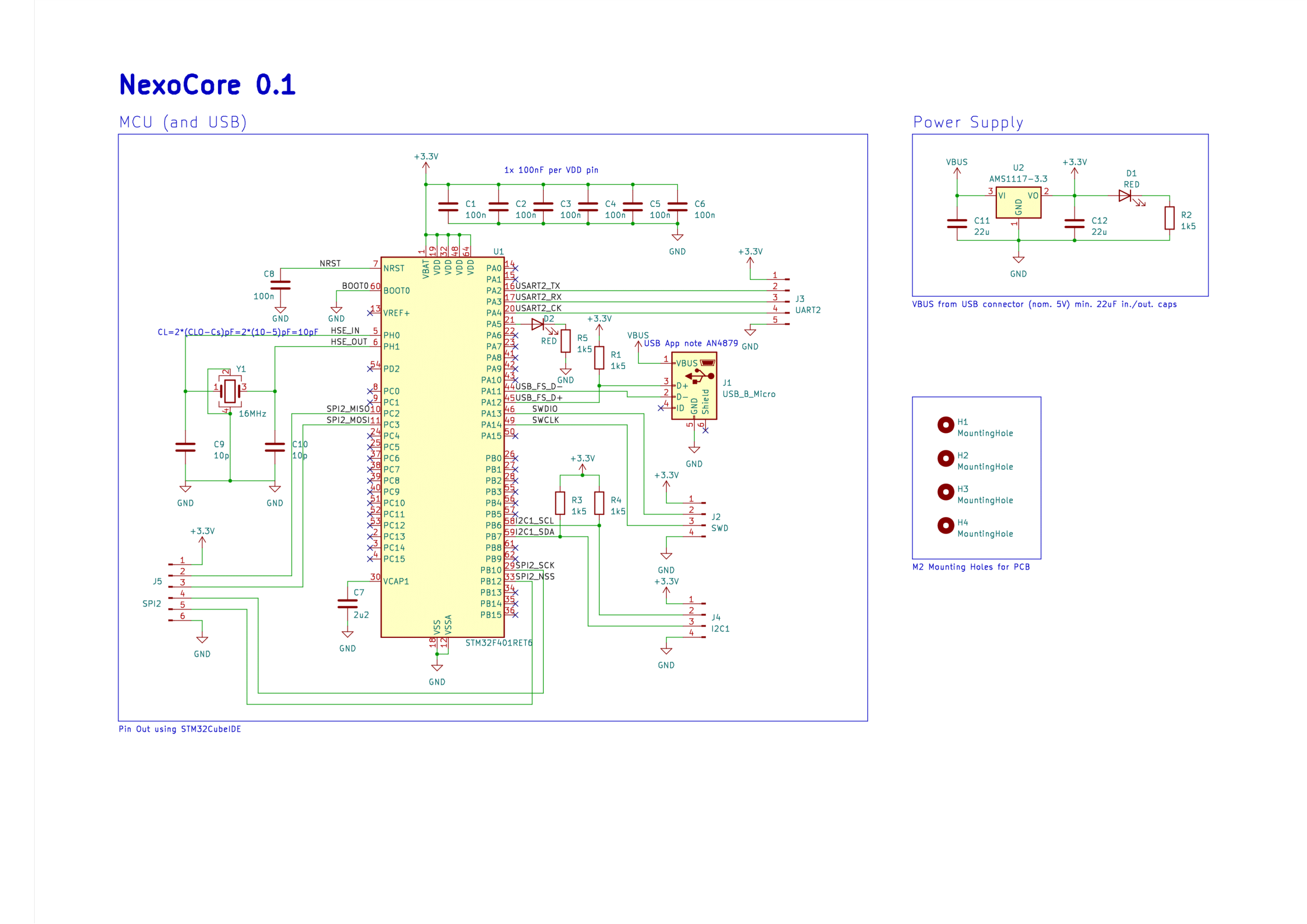
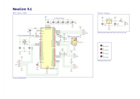
Schaltplan NexoCore 0.1 MCU und Power Supply
NexoCore 0.1 MCU (and USB) Power Supply +3.3V VBUS U2 AMS1117-3.3 RED D1 R2 1k5 C11 22u C12 22u GND C1 100n C2 100n C3 100n C4 100n C5 100n C6 100n GND +3.3V VBUS USB App nano ANA47 GND USB_B_Micro J3 UART2 J1 SWD J2 I2C1 STM32F401RET6 Pin Out using STM32CubeIDE
in „Hilfe benötigt - Debugger erkennt STM32F401RE-Mikrocontroller nicht?“ · Mikrocontroller und Digitale Elektronik · · Schaltpläne
-
Datei
mmc_stm32f1.c
/*------------------------------------------------------------------------*/ /* STM32F100: MMCv3/SDv1/SDv2 (SPI mode) control module */ /*------------------------------------------------------------------------*/ /* / Copyright (C) 2014, ChaN, all right reserved. / / * This software
in „STM32F103: Problem mit ChanFat und SD karte“ · Mikrocontroller und Digitale Elektronik ·
-
Datei
mmc_stm32f1.c
/*------------------------------------------------------------------------*/ /* STM32F100: MMCv3/SDv1/SDv2 (SPI mode) control module */ /*------------------------------------------------------------------------*/ /* / Copyright (C) 2014, ChaN, all right reserved. / / * This software
in „STM32F103 diskio.c für Chan FatFs SD Karten Treiber“ · Projekte & Code ·
-
Datei
mmc_stm32f1.c
/*------------------------------------------------------------------------*/ /* STM32F100: MMCv3/SDv1/SDv2 (SPI mode) control module */ /*------------------------------------------------------------------------*/ /* / Copyright (C) 2014, ChaN, all right reserved. / / * This software
in „STM32F103 diskio.c für Chan FatFs SD Karten Treiber“ · Projekte & Code ·
-
Datei
stm32_ub_uart.c
//-------------------------------------------------------------- // File : stm32_ub_uart.c // Datum : 28.07.2015 // Version : 1.5 // Autor : UB // EMail : mc-4u(@)t-online.de // Web : www.mikrocontroller-4u.de // CPU : STM32F4 // IDE : CooCox CoIDE 1.7.8 // GCC : 4.9 2015q2 //
in „STM32F4 USART“ · Mikrocontroller und Digitale Elektronik ·
-
Datei
readme.txt
fuer diese MCU im Netz verglichen mit AVR und STM32 relativ duerftig. Auch freie Compiler hierfuer sind fast nicht verfuegbar und ausser dem SDCC habe ich keinen freien (zumindest nicht limitierten) Compiler hierfuer gefunden. Von Cosmic gibt es zwar
-
PDF
spwf01.pdf
equipment • Machine-to-machine communication SPWF01SC Features • 2.4 GHz IEEE 802.11 b/g/n transceiver • STM32 ARM Cortex-M3 • 1.5 MB Flash memory • 64 KB RAM memory • 32 kHz XTAL to support low power modes • 16 GPIOs, serial port (UART, SPI, I2C) interfaces available • Small form factor: 26.92 x 15.24 x 2.35
in „Wlan2Serial Modul für 5 euro“ · Mikrocontroller und Digitale Elektronik ·
-
PDF
pensor.pdf
1 2 3 4 5 6 7 8 +3.3V +3.3V A 0 0 A 1 9 k 1 1 C39 V+ D1 R R 4 O D N1 STM32G051 6 CSB D V 100n MIC5236-3.3 +3.3V V SCL 2 SCK X2:2 2 IN OUT 3 4 VDD INT 7 L1 SDA 4 SDI 4 EN ERR 1 F.B.,0.2A 4 5 SDO 1 C3 C12 * C11 C10 C8 C7 C2 D2 100n 68u
in „Datenlogger Pendeluhr“ · Mikrocontroller und Digitale Elektronik ·
-
Datei
STM32F4_lcd.c
// Anschluß einer LC-Anzeige 2x16 an das STM32F4-Discovery-Board // lcd_init() muss als erste Funktion aufgerufen werden. Danach sollten // lcd_cmd() und lcd_zeichen() Befehle und Daten korrekt ausgeben. /* Das LCD-Modul wird im 4-Bit Modus betrieben
in „LCD-Modul 2x16 am STM32F4Discovery-Board“ · Projekte & Code ·
-
Datei
tools.c
uint32_t*)&datastream[BytePos],bitPos,1); else /* Zelle ist tot, also 0 */ //datastream[BytePos] &= ~(1 << bitPos); set_bit((uint32_t*)&datastream[BytePos],bitPos,0); } } } /* Füllt alle Datenbereiche 0..7
in „STM32F1xx: Wie GOL am "Leben" halten?“ · Mikrocontroller und Digitale Elektronik ·
-
Datei
sysf103_init.c
/* ------------------------------------------------------------- sysf103_init.c initialisiert MCU STM32F103 fuer einen "allgemeinen" Gebrauch. Das System wird auf 72MHz externer Takt eingestellt, die Funktion < sys_tick_handler > wird jede ms per Interrupt ausgefuehrt und in dieser
in „Einstieg Mikrocontroller Atmel“ · Mikrocontroller und Digitale Elektronik ·
-
Datei
new_1.txt
in keil debugger ;enable ETM TRACE on Stm32L151 WHISKER1 Data.Set E:0xE0041FB0 0xC5ACCE55 ; unlock trace control registers WHISKER1 Data.Set E:0xE0041000 0x00000910 ;1D1E ; configure trace - write 0x1D1E to ETM Control Register WHISKER1 Data.Set
in „Trace auf Lauterbach PowerDebug USB3 + CombiProbe mit STM32L151“ · Mikrocontroller und Digitale Elektronik ·