
-
PDF
TSynth_Schematic_V1_1.pdf
CAN1TX_SCL0 I1 8 C21 Retrig_LED 31 MUX2_Com 1 7 C22 34_A15_CAN1TX_SDA0 COM I2 J6 Tempo_LED 32 35_A16_PWM A11 57 I3 6 C23 Unison_Btn 33 56 U3 5 C24 SPI Display 36_A17_PWM A10 CD74HC4067M I4 Unison_LED 34 55 4 C25 37_A18_PWM_SCL1 AREF I5 C26 MUX1_Com 35 38_A19_PWM_SDA1 VUSB 54 (Not VUSB on 54, 10 S0 I6 3
in „Electrotechnic T-Synth DIY Synthesizer - Platinenanalyse“ · Mikrocontroller und Digitale Elektronik ·
-
Datei
main_2014_09_29.c
//ans LCD schicken // break; // default : // break; // } //if(hex==1); //else{ if(channel9>550) { PWM_ON=1; richtung=1; soll=(channel9-512)*3; } else { if(channel9<490) { PWM_ON=1; richtung=2; soll=(512-channel9)*3; } else { start=0; CloseOC2(); PWM=0; PWM_ON=0; e=0; esum=0; } } //} if(PWM_ON==1) { if(PWM==0) { OpenOC2( OC_ON | OC_TIMER_MODE16 | OC_TIMER3_SRC | OC_CONTINUE_PULSE | OC_LOW_HIGH , pwm_ein , pwm_aus ); PWM=1; } } /////////////////PI-Regler/////////////////////// e = soll-ist; //Vergleich
in „BLDC-Regler mit PIC32“ · Mikrocontroller und Digitale Elektronik ·
-
Datei
P16081220.c
; PWM_ch2_stop(); } if(Tank_st != ERROR) PWM_ch1_on(); Oel_st = SNSOK; } } //Verify if the sensor is connected else if (oel_prom <= LADCL){ SRN_BLK &= (Oel_st == DSCND) ? TRUE : FALSE; if((Tank_st != ERROR
in „Mikrocontroller an 3 Sensoren notaus auslösen(Atmega88a/Atmega48a)“ · Mikrocontroller und Digitale Elektronik ·
-
Datei
TimerI_.h
Timer on Compare Match (Auto Reload) * Glitch Free, Phase and Frequency Correct Pulse Width Modulator (PWM) * Variable PWM Period * High Speed Asynchronous and Synchronous Clocking with Dedicated Prescaler * Independent Dead Time Generators for Each PWM Channel * Fault Protection Unit Can Disable PWM Output
in „C++ Klassenbibliothek für AVR“ · Mikrocontroller und Digitale Elektronik ·
-
PDF
LDD-nnnL.pdf
FullloaNote.300mA 350mA 500mA 600mA 700mA DC CURRENT No load 5mA FILTER Capacitor Leave open if not use PWM DIMMING REMOTE ON/OFF Power ON with dimming: DIM ~ -Vin >3.5 ~ 8VDC or open circuit & Power OFF : DIM ~ -Vin < 0.5VDC or short PWM FREQUENCY 100 ~ 1KHz ON/OFF CONTROL QUIESCENT INPUT CURRENT 1mAat PWM
in „LDD-300 und BAM“ · Mikrocontroller und Digitale Elektronik ·
-
PDF
XMega-FPGA_V0.0.01.pdf
_0/3.6C 36 86 C_PWM_9/4.5B 37 PE1 PQ1 87 C_FPGA_STROBE_1/3.6C D C_PWM_10/4.5B 38 PE2 PQ2 88 C_FPGA_STROBE_2/3.6C D C_PWM_11/4.5B PE3 PQ3 C_FPGA_STROBE_3/3.6C C_PWM_12/4.5B 39 PE4 C_PWM_13/4.5B 40 PE5 PR0 91 C_FPGA_DONE
-
PDF
DM164.pdf
0 1 65535 1st PWM cycle 2nd PWM cycle 3rd PWM cycle IOUT0 (ONEST=H) (ONEST=L) Figure 9. One-Shot Operation Grayscale PWM Operation When DCKPH=L, the grayscale PWM cycle starts with the falling edge of LTH (see Figure
in „8 RGB Leds stufenlos ansteuern“ · Mikrocontroller und Digitale Elektronik ·
-
PDF
DM164.pdf
0 1 65535 1st PWM cycle 2nd PWM cycle 3rd PWM cycle IOUT0 (ONEST=H) (ONEST=L) Figure 9. One-Shot Operation Grayscale PWM Operation When DCKPH=L, the grayscale PWM cycle starts with the falling edge of LTH (see Figure
in „20mA Led Treiber mit möglichst vielen Kanälen“ · Mikrocontroller und Digitale Elektronik ·
-
PDF
447.pdf
half-bridge connected to a DC voltage source. Figure 3-1. Voltage generation using a half-bridge. PWM H VD VOUT C PWM L 3.1.1 PWM The average voltage of the output, V OUT, can be regulated between 0V and V DC by applying two inverted pulse-width modulated (PWM) signals to the two switches, PWM H and
in „Synchron- / BLDC - Motor zum Laufen bringen“ · Mikrocontroller und Digitale Elektronik ·
-
 Bild
Bild
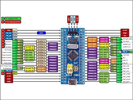
Pinbelegung eines Mikrocontroller-Boards
PAS1, I2C1 SCL, CAN1 RD, PB7, D15, USART1_RX, I2C1 SCL, Serial1 TX, D10, PB6, USART1_TX, I2C1 SDA, PWM3/2, PWM3/1, PWM2/1, PWM1/1, PWM1/2, PWM1/3, PWM1/4, PWM2/3, PWM2/4, PWM3/3, PWM3/4, PWM2/2, PWM1/3N, PWM1/2N, SPI1 MOSI, SPI1 MISO, SPI1 SCK, SPI1 NSS, Serial1 RX, Serial1 TX, USB D, USB D, PB15, PB13
in „STM32 GPIO finder“ · Mikrocontroller und Digitale Elektronik · · Screenshots
-
PDF
TLC59116.pdf
PWM3 7:0 IDC3[7:0] R/W 0000 0000 PWM3 individual duty cycle 06h PWM4 7:0 IDC4[7:0] R/W 0000 0000(2) PWM4 individual duty cycle (2) 07h PWM5 7:0 IDC5[7:0] R/W 0000 0000 PWM5 individual duty cycle 08h PWM6
in „Verstehe TWI überhaupt nicht“ · Mikrocontroller und Digitale Elektronik ·
-
Datei
Pulver_Ofen_Temp_Steuerung_Display.c
0b00011001,//9 }; while (1==1) { waitms(100); val=getadc(0); set=getadc(1); //printf("%d %d %d %d\n",pwm,pwm_ctr,val,convert2degree(degree)); //debug //printf("%d \n",convert2degree(val)); vergl=(convert2degree(val)); /*pwm_ctr++; if (pwm_ctr>=10) { pwm_ctr=0; //wenn PWm counter >10 dann pwm_ctr wert gleich 0 pwm=val-SOLLWERT; // ADC Wert - ADC sollwert(adc Tempwert) } if (pwm<0) //wenn PWM kleiner 0 dann pwm=0 { pwm=0; } */ if(vergl>=set) { PORTD = 0b01000000; //off } else { PORTD = 0b11100000; //on } /*if
in „ADC Wert in Temperatur wandeln und auf Display ausgeben“ · Mikrocontroller und Digitale Elektronik ·
-
PDF
Vollbr_cke_VNH3SP30.pdf
temperature IN TTR Thermal Reset Temperature 135 °C THYST Thermal Hysteresis 7 15 °C 5/26 1 VNH3SP30 PWM ELECTRICAL CHARACTERISTICS (continued) Symbol Parameter Test Conditions Min Typ Max Unit V pwl PWM low level voltage 1.5 V pwl Low level PWM pin current Vpw=1.5V 1 A V pwh PWM high level voltage 3.25 V pwh High level PWM pin current Vpw=3.25V 10 A Vpwhhyst PWM hysteresis voltage 0.5 V pw = 1 mA VCC+0.3 V CC+0.7 V CC+1.0 V Vpwcl PWM clamp voltage pw = -1 mA -5.0 -3.5 -2.0 V V pwtest Test mode PWM pin voltage -3.5 -2.0
in „VNH3SP30 auch als Halbbrücke“ · Mikrocontroller und Digitale Elektronik ·
-
Datei
Steuerung_regelbar.bas
Dim Helligkeit_gross As Integer Dim Helligkeit_klein As Integer Config Debounce = 20 Config Timer1 = Pwm , Pwm = 8 , Prescale = 1 , Compare A Pwm = Clear Down , Compare B Pwm = Clear Down Enable Timer1 Start Timer1 Config Timer2 = Pwm , Pwm = On , Prescale = 1 , Compare Pwm = Clear Down Enable Timer2 Start
in „7ter Atmega 8 geht nur teilweise kaputt“ · Mikrocontroller und Digitale Elektronik ·
-
Datei
main.c
=MaxZykluszeit (Sekunden) ist. */ Timer++; return; } void fade_red (uint8_t t, uint8_t stPWM, uint8_t spPWM) { return; } void fade_blau (uint8_t t, uint8_t stPWM ,uint8_t spPWM) { return; } void fade_gruen (uint8_t t, uint8_t stPWM, uint8_t spPWM) { return; } void do_pause (uint8_t t) { return
in „Moodlight Sourcecode hilfe“ · Mikrocontroller und Digitale Elektronik ·
-
Datei
main.c
); void Einordner (uint8_t rate); // // // ++++ Main-Programm ++++ // int main(void) { DDRB |= (1<<PWM_0); // Ausgang PWM als Farbe-Dimmer DDRB |= (1<<PWM_1); // Ausgang PWM als Helligkeit-Dimmer DDRB &= ~(1<<S2_hell_ab); // Taster Hell ab S2 DDRB &= ~(1<<S1_hell_auf); // Taster Hell auf S1 PORTB |=
in „Zwei PWM steuern LED-Steifen mit Attiny 85,Schaltbild neu“ · Mikrocontroller und Digitale Elektronik ·
-
PDF
AS5410_DataSheet_Rev1.5.pdf
2 1 Limits the PWM duty cycle to a minimum value D5 PWMLimitLo 1 0 D4 PWMLimitLo 0 1 D3 PWMEn 0 PWM Enable, Enables the PWM output D2 PWM PreScale 2 0 D1 PWM PreScale 1 1 PWM PreScale, Sets PWM frequency and resolution
in „SPI funktioniert nicht“ · Mikrocontroller und Digitale Elektronik ·
-
Datei
top_sub_melodyPlayer.vhd
STD_LOGIC_VECTOR ( 7 downto 0 ); waveOut : out STD_LOGIC_VECTOR ( 7 downto 0 ) ); end component; component pwmDac port ( clk : in STD_LOGIC; pwmValue: in STD_LOGIC_VECTOR ( 9 downto 0 ); pwmOut : out STD_LOGIC ); end component; signal sequencerStep : STD_LOGIC_VECTOR ( 7 downto 0 ); signal system_pwmValue :
-
PDF
WT588D-U_Voice_Module.pdf
RESET RESET Reset pin 8 DAC DAC DAC Audio output pin, need an external amplifier to drive speaker 9 PWM+ PWM+ PWM+ Audio output pin, which can directly drive speaker with the PWM- 10 PWM- PWM- PWM- Audio output pin, which can directly drive speaker with the PWM+ 11 P14 SPI-FLASH_DI use for externadownload
in „WT588D Voice Modul Tonqualität“ · Analoge Elektronik und Schaltungstechnik ·
-
Datei
main.c
aktivueren Timer 1 //TCCR0B |= (1 << CS01) | (1<<CS00); //intern Prescaler = 1024 Timer 0 --> 8khz PWM //TCCR1B |= (1 << CS11) | (1<<CS10); // Intern Prescaler = 1024 Timer 1 --> 8khz PWM // TCCR1B |= (1 << CS11)|(1 << CS10); // TCCR0B |= (1 << CS01)|(1 << CS00); // OCR0A = 180; //0% PWM, 255= 100% PWM, BPWM1 // OCR0B= 100; //0% PWM, 255= 100% PWM, APWM1 // OCR1A = 150; //0% PWM, 255= 100% PWM, CPWM1 // OCR1B= 190; // 0% PWM, 255= 100% PWM, APWM2 char systembyte = 0b11001111; char systembyte2 = 0b11100000; char motorbyte1 = 0b11011101
in „Allegro A4960 bzw. A4964“ · Mikrocontroller und Digitale Elektronik ·
-
Datei
Board_Mono_PWM_3.c
für Umwandlung und Ausgabe char puffer3[7]; // Charpuffer für Umwandlung und Ausgabe static uint8_t pwm_cnt=0; // Zählt die PWM-Schritte static uint8_t pwm_soll=150; // Sollwert für PWM, LED soll 150 von 255 Takten an sein //************ Interrupt ISR ************* ISR(INT0_vect) //Interrupt extern Taster
in „Timerproblem bei PWM nach Tutorial „SOFT-PWM“ ( Atmega8)“ · Mikrocontroller und Digitale Elektronik ·
-
Datei
main.cpp
. // Clear Timer on Compare Match (CTC) mode is not exactly what we want for PWM // typically. We want Pulse Width Modulator A Enable (PWM1A). // TCCR1: // CTC1 = 0 // PWM1A = 1 (Enable PWM A) // COM1A1:0 = 10 (Clear OC1A on Compare Match, Set on 0x00) -> Non-Inverted PWM // CS13:10 = 0010 (Prescaler = 2) TCCR1 = 0; TCCR1 |= (1 << PWM1A) | (1 << COM1A1) | (1 << CS11); // OCR1C sets the TOP value (Frequency) OCR1C = PWM_TOP; // Initial Duty Cycle 0 OCR1A = 0; // Set PB1 as Output pinMode(PIN_PWM, OUTPUT); } void setup() { setupPWM
in „Suche Lüfter PWM IC mit Temp. Regelung“ · Mikrocontroller und Digitale Elektronik ·
-
Datei
demo.c
OCR1A #elif defined(__AVR_ATmega8__) # define OC1 PB1 # define DDROC DDRB # define OCR OCR1A # define PWM10 WGM10 # define PWM11 WGM11 #elif defined(__AVR_ATmega64__) || defined(__AVR_ATmega128__) # define OC1 PB5 # define DDROC DDRB # define OCR OCR1A # define PWM10 WGM10 # define PWM11 WGM11 #else # error
in „Probleme mit WINAVR“ · Mikrocontroller und Digitale Elektronik ·
-
PDF
PCA9533.pdf
PWM0 PWM0 PWM0 PWM0 PWM0 PWM0 PWM0 PWM0 [7] [6] [5] [4] [3] [2] [1] [0] Default 1 0 0 0 0 0 0 0 PCA9533_3 © NXP B.V. 2009. All rights reserved. Product data sheet Rev. 03 Ñ 27 April 2009 5 of 24 NXP Semiconductors
in „[V] 20St 4-Bit I2C LED PWN Treiber NXP PCA9533 (SO8) (1€/St)“ · Markt ·
-
PDF
Novatek_NT96650.pdf
usefulness of any such information. NT96650BG-ES 2012-09-17 Name PWM M-shutter u-stepping SPI PWM1 PWM1 O ME_SHUT1 O uSTP1_B O PWM3 PWM3 O uSTP1_D O PWM5 PWM5 O uSTP2_B O SPI3_CS# O L PWM7 PWM7 O uSTP2_D O SPI3_DI O PWM8 PWM8 O uSTP3_A O PWM10 PWM10 O uSTP3_C O A PWM12 PWM12 O uSTP4_A O I PWM14 PWM14 O uSTP4_C O PWM16 PWM16 O ME_SHUT0 O uSTP4_D O PWM17 PWM17 O ME_SHUT1 O T PWM19 PWM19 O Peripheral I/O (19) N Pin No. Name Type Reset Descriptions E19 P_GPIO[0]* / I/OD I
in „Unbekannte Firmware disassemblieren“ · Mikrocontroller und Digitale Elektronik ·
-
PDF
PCA9533.pdf
PWM0 PWM0 PWM0 PWM0 PWM0 PWM0 PWM0 PWM0 [7] [6] [5] [4] [3] [2] [1] [0] Default 1 0 0 0 0 0 0 0 PCA9533_3 © NXP B.V. 2009. All rights reserved. Product data sheet Rev. 03 Ñ 27 April 2009 5 of 24 NXP Semiconductors
in „[V] einige 4 Bit I2C LED PWN Treiber NXP PCA9533 (SO8)“ · Markt ·
-
PDF
PCA9533.pdf
PWM0 PWM0 PWM0 PWM0 PWM0 PWM0 PWM0 PWM0 [7] [6] [5] [4] [3] [2] [1] [0] Default 1 0 0 0 0 0 0 0 PCA9533_3 © NXP B.V. 2009. All rights reserved. Product data sheet Rev. 03 Ñ 27 April 2009 5 of 24 NXP Semiconductors
in „[V] 4-Bit I2C LED PWN Treiber NXP PCA9533 (TSSOP-8) (1€/St)“ · Markt ·
-
PDF
PCA9533.pdf
PWM0 PWM0 PWM0 PWM0 PWM0 PWM0 PWM0 PWM0 [7] [6] [5] [4] [3] [2] [1] [0] Default 1 0 0 0 0 0 0 0 PCA9533_3 © NXP B.V. 2009. All rights reserved. Product data sheet Rev. 03 Ñ 27 April 2009 5 of 24 NXP Semiconductors
in „[V] 4-Bit I2C LED PWN Treiber NXP PCA9533 (TSSOP-8) (12€ / 20St)“ · Markt ·
-
PDF
PCA9533.pdf
PWM0 PWM0 PWM0 PWM0 PWM0 PWM0 PWM0 PWM0 [7] [6] [5] [4] [3] [2] [1] [0] Default 1 0 0 0 0 0 0 0 PCA9533_3 © NXP B.V. 2009. All rights reserved. Product data sheet Rev. 03 Ñ 27 April 2009 5 of 24 NXP Semiconductors
in „[V] nochmal 4-Bit I2C LED PWN Treiber NXP PCA9533 (TSSOP-8) (12€ / 20St)“ · Markt ·
-
PDF
PCA9533.pdf
PWM0 PWM0 PWM0 PWM0 PWM0 PWM0 PWM0 PWM0 [7] [6] [5] [4] [3] [2] [1] [0] Default 1 0 0 0 0 0 0 0 PCA9533_3 © NXP B.V. 2009. All rights reserved. Product data sheet Rev. 03 Ñ 27 April 2009 5 of 24 NXP Semiconductors
in „[V] 4-Bit I2C LED PWN Treiber NXP PCA9533 (TSSOP-8) (12€ / 20St)“ · Markt ·
-
PDF
PCA9533.pdf
PWM0 PWM0 PWM0 PWM0 PWM0 PWM0 PWM0 PWM0 [7] [6] [5] [4] [3] [2] [1] [0] Default 1 0 0 0 0 0 0 0 PCA9533_3 © NXP B.V. 2009. All rights reserved. Product data sheet Rev. 03 Ñ 27 April 2009 5 of 24 NXP Semiconductors
in „[V] 4-Bit I2C LED PWN Treiber NXP PCA9533 (TSSOP-8) (30St/17€)“ · Markt ·
-
PDF
PCA9533.pdf
PWM0 PWM0 PWM0 PWM0 PWM0 PWM0 PWM0 PWM0 [7] [6] [5] [4] [3] [2] [1] [0] Default 1 0 0 0 0 0 0 0 PCA9533_3 © NXP B.V. 2009. All rights reserved. Product data sheet Rev. 03 Ñ 27 April 2009 5 of 24 NXP Semiconductors
in „[V] 4-Bit I2C LED PWN Treiber NXP PCA9533 (TSSOP-8) (30St/12€)“ · Markt ·
-
PDF
PCA9533.pdf
PWM0 PWM0 PWM0 PWM0 PWM0 PWM0 PWM0 PWM0 [7] [6] [5] [4] [3] [2] [1] [0] Default 1 0 0 0 0 0 0 0 PCA9533_3 © NXP B.V. 2009. All rights reserved. Product data sheet Rev. 03 Ñ 27 April 2009 5 of 24 NXP Semiconductors
in „[V] 4-Bit I2C LED PWN Treiber NXP PCA9533 (TSSOP-8) (30St/12€)“ · Markt ·
-
Datei
main.c
0); if (pwm_setting[1] > pwm_cnt) tmp |= (1<<1); if (pwm_setting[2] > pwm_cnt) tmp |= (1<<2); if (pwm_setting[3] > pwm_cnt) tmp |= (1<<3); if (pwm_setting[4] > pwm_cnt) tmp |= (1<<4); if (pwm_setting[5] > pwm_cnt) tmp |= (1<<5); if (pwm_setting[6] > pwm_cnt) tmp |= (1<<6); if (pwm_setting[7] > pwm_cnt) tmp |= (1<<7); PWM_PORT = (tmp<<1); // PWMs aktualisieren if (pwm_cnt==(uint8_t)(PWM_STEPS-1)) pwm_cnt=0; else pwm_cnt++; } **/ ISR
in „Master und 3 Slaves, Kommunikation läuft nicht rund Bitte um Hilfe“ · Mikrocontroller und Digitale Elektronik ·
-
PDF
Arduino_Mega_schematics.pdf
INT5)PE5 7 PE5 pwm PE3 pwm 6 5 n D n r l h . 3 ADC10 87 PK2(ADC10/PCINT18) (OC3B/INT4)PE4 6 PE4 pwm PG5 5 4 u L t d n i 2 ADC9 88 PK1(ADC9/PCINT17) (OC3A/AIN1)PE3 5 PE3 pwm PE5 pwm 4 3 r P s e e o 1 ADC8 89 PK0(ADC8/PCINT16
in „Arduino Mega 2560, schaltschranktauglich“ · Projekte & Code ·
-
PDF
AS5045.pdf
range). This tolerance can be cancelled by measuring the complete duty cycle as shown above. Figure 8. PWM Output Signal Angle PW MIN 0 deg (Pos 0) 1µs 4097µs PW MAX 359.91 deg (Pos 4095) 4096µs 1/fPWM www.austriamicrosystems.com Revision 1.7 16 – 33 AS5045 Data Sheet 9.1 Changing the PWM Frequency The PWM
in „Vom Sensor zum VHDL Board (D0-Board)“ · FPGA, VHDL & Co. ·
-
Datei
main.c
#include <util/delay.h> #define Ledport PORTB #define R PB1 #define G PB2 #define B PB3 #define R_PWM OCR2 #define G_PWM OCR1A #define B_PWM OCR1B int my_delay(void); int main(void) { DDRB |= (1 << PB3); //PB3-PB1 als Ausgang DDRB |= (1 << PB2); DDRB |= (1 << PB1); PORTB &= ~(1 << PB3); PORTB &= ~(1
in „RGB Fader Atmega8 Anfänger“ · Mikrocontroller und Digitale Elektronik ·
-
Datei
Orlyjonok.asm
µC = ATmega16 * ;* Systemtakt = 8MHz * ;************************************ ; PA0 Wahlschalter W1-PWM in ; PB0 Auto in out ; 1 Wahlschalter W2-PWM in ; 1 Auto out out ; 2 Wahlschalter ZR-PWM in ; 2 Auto in in ; 3 Wahlschalter KR-PWM in ; 3 OC0 out ; 4 Wahlschalter W1-EL in ; 4 Auto out in ; 5 Wahlschalter
in „AVR Assembler: ret springt an falsche Stelle zurück“ · Mikrocontroller und Digitale Elektronik ·
-
PDF
CCP_Tricks.pdf
................20 TIP #9: Generating the Time Tick for a RTOS.......23 TIP #10: 16-Bit Resolution PWM.............................24 TIP #11: Sequential ADC Reader............................26 TIP #12: Repetitive Phase Shifted Sampling...........28 PWM Tips 'n Tricks TIP #13: Deciding on PWM Frequency
in „Lüfter über PWM, Bauteilauswahl?!?“ · Mikrocontroller und Digitale Elektronik ·
-
Datei
Tiny_50Hz.c
all PWM pins as output. The PWM configuration itself is not altered * in any way by running this function. */ static void EnablePWMOutputs(void) { DDRB |= PWM_PATTERN_PORTB; } /*! \brief Disables PWM output pins * * This function disables PWM outputs by setting the port direction for * all PWM pins as inputs, thus overriding the PWM. The PWM configuration * itself is not altered in any way by running this function. */ static void DisablePWMOutputs
in „Theorie Wechselrichter 12V DC -> 230V AC“ · Analoge Elektronik und Schaltungstechnik ·
-
PDF
HV9910.pdf
terminal of the MOSFET. The voltage from the sense resistor is applied to the CS pin of the HV9910. The PWM dimming scheme can be implemented by applying When the voltage at CS pin exceeds a peak current sense an external PWM signal to the PWM_D pin. The PWM signal voltage threshold, the gate drive signal
-
Datei
main.c
#define PWM_PORT PORTC #define F_CPU 12000000L // Systemtakt in Hz #define F_PWM 100 // PWM-Frequenz in Hz #define PWM_STEPS 90 // PWM-Schritte pro Zyklus(1..256) #define PWM_channels 3 #define T_PWM (F_CPU/(F_PWM*PWM_STEPS)) // Systemtakte pro PWM-Takt #if (T_PWM<(93+5)) #error T_PWM zu klein, F_CPU muss vergrösst werden oder F_PWM oder PWM_STEPS verkleinert werden #endif #include <avr/wdt.h> #include <stdint.h>
in „Probleme bei VUSB- Bachelorarbeit“ · Mikrocontroller und Digitale Elektronik ·
-
Datei
main_ohne_.C.c
| (1<<COM21) | (1<<CS22)| (1<<CS21) | (1<<CS20); /* Fast PWM nicht invertiert (ORC2) */ /* Presacaller 1:1024 Periodendauer 16,4ms ~ 61 HZ*/ DDRD |= (1<<SERVO_PWM); SERVO_MITTE; } void MOTOR_PWM (uint16_t A, uint16_t B) { OCR1A = A; OCR1B = B; } int main(void
in „Externe .c bringt nur theater“ · Mikrocontroller und Digitale Elektronik ·
-
Datei
ch559_keil.h
clocks if turning output level from low to high sfr PIN_FUNC = 0xCE; // pin function selection #define bPWM1_PIN_X 0x80 // PWM1/PWM2 alternate pin enable: 0=PWM1/PWM2 on P2.4/P2.5, 1=PWM1/PWM2 on P4.3/P4.5 #define bTMR3_PIN_X 0x40 // PWM3/CAP3 alternate pin enable: 0=PWM3/CAP3 on P1.2, 1=PWM3/CAP3 on P4.2
in „uC für 0,20€ CH552 / CH554 von WCH Billig Micro mit USB Funktion, Chip vorstellung“ · Mikrocontroller und Digitale Elektronik ·
-
Datei
ch559_iar.h
output level from low to high SFR unsigned char PIN_FUNC @ 0xCE; // pin function selection #define bPWM1_PIN_X 0x80 // PWM1/PWM2 alternate pin enable: 0=PWM1/PWM2 on P2.4/P2.5, 1=PWM1/PWM2 on P4.3/P4.5 #define bTMR3_PIN_X 0x40 // PWM3/CAP3 alternate pin enable: 0=PWM3/CAP3 on P1.2, 1=PWM3/CAP3 on P4.2
in „Doppelbelegung SBIT bei IAR“ · Mikrocontroller und Digitale Elektronik ·
-
PDF
20002234D.pdf
80 ( ( 70 e 250 y VIN 0.8V V = 1.2V o n 60 IN M 225 V = 3.3V i 50 M OUT i W E 40 P 200 30 IQ 175 20 PWM / PFM 10 PWM Only 150 0 -40 -25 -10 5 20 35 50 65 80 0.01 0.1 1 10 100 1000 Ambient Temperature (°C) I (mA) OUT FIGURE 2-2: V OUT Q I vs. Ambient FIGURE 2-5: 3.3V V OUT PFM/PWM Mode Temperature in PWM
in „NRF24L01+ durch MCP1640 gestört?“ · Mikrocontroller und Digitale Elektronik ·
-
PDF
3957_Datenblatt.pdf
AC Timing PWM RC Fixed Off-time t C = 470 pF, R = 43 kΩ 18.2 20.2 22.3 µs OFF RC T T PWM Turn-Off Time tPWM(OFF) Current-Sense Comparator Trip — 1.0 1.5 µs to Source OFF, I = 100 mA OUT Current-Sense Comparator Trip — 1.4 2.5 µs to Source OFF, I = 1.5 A OUT PWM Turn-On Time tPWM(ON) IRCCharge ON to Source ON, — 0.4 0.7 µs I = 100 mA OUT IRCCharge ON to Source ON, — 0.55 0.85 µs I = 1.5 A OUT PWM Minimum On Time tON(min) VCC = 5.0 V, RT≥ 43 kΩ, CT= 470 pF 1.0
in „Library für 3957 Microstepping Motor Driver?“ · Mikrocontroller und Digitale Elektronik ·
-
Datei
config.h
29=1MHz // SPI-IOSET-Maske #define SPI0_IOSET_MASK 0x00001500 // SCK,MISO and MOSI for SPI0 usage //PWM #define PWM_PCLK_DIV 2 //main PWM #define PWM_FREQ1 (44000) //frq for main PWM0 the Master PWM frq (also used for sound) #define PWM_FREQ2 (36000) //frq for LCD Backlight must smaler then PWM_FREQ1 #define PWM_FRE_RC5_S (36000) //frq for IR Transmitter must smaler then PWM_FREQ1 #define PWMTICSperSEC (PCLK / (PWM_PCLK_DIV + 1)) #define PWM_MR0INIT (U32)((PWMTICSperSEC/PWM_FREQ1) + 0.5) //Main PWM TIMER //
in „Spielereien mit dem LPC-P2148“ · Mikrocontroller und Digitale Elektronik ·
-
Datei
config.h
!!war1 // SPI-IOSET-Maske #define SPI0_IOSET_MASK 0x00001500 // SCK,MISO and MOSI for SPI0 usage //PWM #define PWM_PCLK_DIV 2 //main PWM #define PWM_FREQ1 (44000) //frq for main PWM0 the Master PWM frq (also used for sound) #define PWM_FREQ2 (36000) //frq for LCD Backlight must smaler then PWM_FREQ1 #define PWM_FRE_RC5_S (36000) //frq for IR Transmitter must smaler then PWM_FREQ1 #define PWMTICSperSEC (PCLK / (PWM_PCLK_DIV + 1)) #define PWM_MR0INIT (U32)((PWMTICSperSEC/PWM_FREQ1) + 0.5) //Main PWM TIMER //
in „Spielereien mit dem LPC-P2148“ · Mikrocontroller und Digitale Elektronik ·
-
Datei
unsauber.ino
Daten für PWM0 0-> PEM 0% ON Wire.write(0x00); // Daten für PSC1 0-> PWM freq 145 HZ Wire.write(0x00); // Daten für PWM2 0-> PEM 0% ON Wire.write(0x05); // Daten für LS0-Register 0x0E -> LED0=PWM0 , LED2=PWM2 ,LED3
in „Nummerneingabe SwitchCase AVR“ · Mikrocontroller und Digitale Elektronik ·
