of all chapters from where you can directly jump to a specific chapter. • Use the Bookmarks on the side bar to jump to any specific chapters or sections from anywhere in the document. Note this PDF document is configured to automatically display Bookmarks when open, which is necessary for an extensive
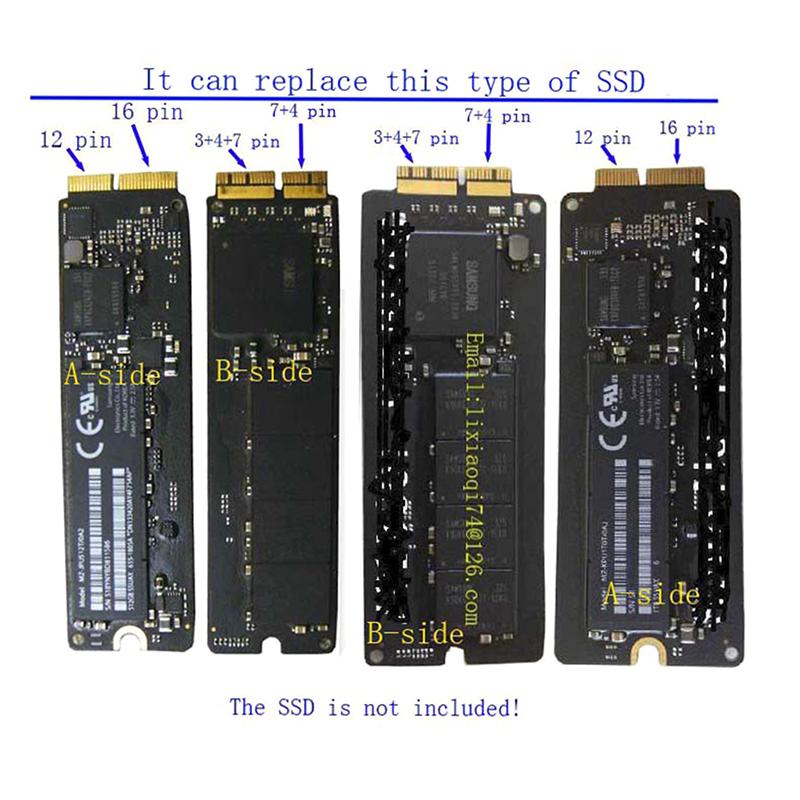
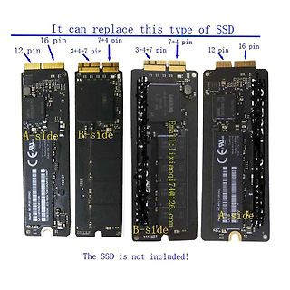
It can replace this type of SSD
16 pin
7+4 pin
7+4 pin
12 pin
16 pin
12 pin
3+4+7 pin
3+4+7 pin
A-side
B-side
Email: lixiaoq174@126.com
B-side
A-side
The SSD is not included!
protrusions, or gate burrs. Mold flash, protrusions, or gate burrs shall not exceed .006 [0.15] per side. 4. This dimension does not include interlead flash. 5. Reference JEDEC registration MS-012, variation AA. www.ti.com EXAMPLE BOARD LAYOUT D0008A SOIC - 1.75 mm max height SMALL OUTLINE INTEGRATED CIRCUIT
upperRightLdrVal + upperLeftLdrVal) /2; // Calculation of the average voltage value of the LDRs on each side. lowerAverageLdr = (lowerRightLdrVal + lowerLeftLdrVal) /2; rightAverageLdr = (upperRightLdrVal + lowerRightLdrVal)/2; leftAverageLdr = (upperLeftLdrVal + lowerLeftLdrVal) /2; Serial.print("upperRightLdrVal
dass ich gerne mit einem Arduino eine LED Leiste (R,G,B,GND) zu betreiben. Dazu nimmt man drei High-Side-Treiber und 3 PWM-Kanäle. Falls die HArdware keine 3 Compare-Ausgänge hat, ist das Stichwort: [[Soft-PWM]]
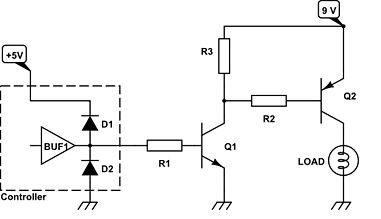
Wenn man eine Verstärkerschaltung o. Ä. zeichnet, dann liegt oben (high side) die Versorgungsspannung und unten (low side) Masse. Ein High-side-Treiber liefert also Versorgungsspannung/-strom an eine Last, deren anderes Ende unten (auf Masse oder in Richtung Messe) liegt.
2X 0.50 (0.2510X S p RECOMMENDED LAND PATTERN e d 0.55 MAX U S 0.05 C B 0.05 C . 0.00 (0.20) 0 C 4 SIDE VIEW 0.35 0 0.25 M b (0.15) p DETAIL A D (0.36) ) 0.55 0.25 S 0.35 w 0.25 1 4 DETAIL A 2X SCALE t 0.56 c NOTES: h 10 5 A. PACKAGE CONFORMS TO JEDEC REGISTRATION MO-255, VARIATION UABD . (0.29) 0.35
M Z 5900 M Z 8700 M Display Symbols 0 to 9 0 to 9 0 to 9 bi-quinary Decimal point right left both sides Viewing direction side side side side Character height (mm) 13 13 10 15.5 Maximum viewing distance (m) ~8 ~8 ~5 ~10 Typical values Ignition voltage Vign 150 150 150 150 Maintaining voltage Vmaint 140
, protrusions, or gate burrs. Mold flash, protrusions, or gate burrs shall not exceed 0.25 mm per side. 5. Support pin may differ or may not be present. www.ti.com EXAMPLE BOARD LAYOUT DBV0005A SOT-23 - 1.45 mm max height SMALL OUTLINE TRANSISTOR PKG 5X (1.1) 1 5X (0.6) 5 SYMM (1.9) 2 2X (0.95) 3 4 (
discontinuity in the tangential field intensity, and the value of this quantity is different on each side of the interface. The postprocessor resolves the conflict by always evaluating the plots at a differentially small distance to the “normal” side of the line. Therefore, by defining the same contour but reversing the order in which the points are specified, plots of the quantity of interest on each side of a boundary can be obtained. 39 Figure 2.22: When in doubt plots and integrals taken on this side of a contour. 2.3.10 Line Integrals Once a contour has been specified in Contours mode, Line Integrals
1 mm and than with borer 2.5-3 mm on the bottom GND side to remove copper surface only. The double side of PCB can be make as it is proposed with soldering the rest of resistor leads through the holes drilled between top and bottom PCB side. This is easy
front; 2. Does not affect the relevant alignment; Slight Notch 3. X≤1mm, Y≤1mm, N≤2. defect Glass side 。 Foreign 1. The foreign body on the side is not controlled; Slight objects 2. The paint pen marks on the side are not controlled; defect Dirty 3. Side oily note printing is not allowed. Cracks Heavy
front; 2. Does not affect the relevant alignment; Notch 3. X≤1mm, Y≤1mm, N≤2. Slight defect Glass side Foreign 1. The foreign body on the side is not controlled; Slight 2. The paint pen marks on the side are not controlled; objects defect Dirty 3. Side oily note printing is not allowed. Cracks Goldfinger
von der Pipe ein Problem mit dem Format. Ich nehme dann tcpdump. Letzte Zeile also z. B. ... =$SID| tcpdump -r - -w test.dmp Mit dem Filtern kann es bei tcpdump und dem Internetanschluss etwas schwierig werden. Also einfach noch eine Pipe nach tshark (von tcpdump aus geht das) und dann kann man Wireshark Display-Filter nehmen. Z. B.: ..., =$SID | tcpdump -r - -w - | tshark -r - -Y "udp.port == 53" filtert DNS. Das Shellskript beendet den Paketmitschnitt nicht. Das sollte man dann in der FritzBox machen.
............................................................. 23 10.1 Shipping Label (on the rear side of TFT-LCD display) .....................................................23 10.2 Carton Package.......................................................................................................
0.228 0.016 0.024 0.012 Notes 1. Plastic or metal protrusions of 0.15 mm (0.006 inch) maximum per side are not included. 2. Plastic or metal protrusions of 0.25 mm (0.01 inch) maximum per side are not included. OUTLINE REFERENCES EUROPEAN ISSUE DATE VERSION IEC JEDEC JEITA PROJECTION SOT96-1 076E03 MS
Instrument: The connecting cables for the heating (13 u. 14; 15 u. 16) must be bridged on the supply side in order to guarantee the complete heating power! The supply of the electronics is effected additionally via diodes uncoupled through the heating connections 13,14, and 15, 16. If the heating voltage
Wenn du die SIDE Anschlüsse mit COM verbindest wird sich vermutlich nur eines der Tore öffnen. Einen Widerstand für die Verbindung zu nutzen ist eine gute Idee um einen Kurzschluss zu verhindern falls die Schaltung
Source an +12V und Drain an den Ausgang. Infineon mit seinen N-Kanal MOSFETs in vielen Smart High-Side Switches (z.B. BTS50025) hat einfach keine Ahnung - oder was wolltest du sagen?
Displayhinterleuchtung des ALCs eine galvanische Trennung zwischen den erreicht. besteht aus vier Side-Looking-Lamps Geräten besteht. Die Spannungsversor- DieR232-Signalestehenandenentspre- (D 501 bis D 504). Aktiviert wird die gung des Moduls erfolgt dabei aus der chendbezeichnetenAusgängen(Pin18bis
activated simultaneously in the application, then the total I OL from SCL/SDA to GND on the master side is the sum of the currents through all pull-up resistors, R p The pass-gate transistors of the TCA9548A are constructed such that the V CC voltage can be used to limit the maximum voltage that is passed
Caution: magnetization vector. Subsequently, an external magnetic field applied perpendicularly to the sides of This is an Electro-static Discharge (ESD) sensitive the film causes the magnetization to rotate and change device. angle. This effect causes the film’s resistance to vary Ordering Guide: with the
board.) Table 5-1 Pin no. symbol function Color of cable 1 VLOW Power supply for lamp (Low voltage side) White 2 NC This is electrically opened. - 3 VHIGH Power supply for lamp (High voltage side) Red 6. Absolute Maximum Ratings Table 6-1 Parameter Symbol Condition Ratings Uni Remark t Input voltage VI
das alte WLan bekannt waren kommen auf natürlich auf die neue Fritzbox drauf, da ja das alte WLAN (SID/PW) auf der neuen Box ist. Okay soweit? Nun nimmt er sich einen Zettel (Papier und Stift, du weißt schon) zur Hand und notiert sich von der alten Fritzbox (die er ja gerade abgebaut hat und in
Data Sheet 1 2007-05 TLE4905L, TLE4935L, TLE4945L, TLE4945-2L Pin Configuration (view on branded side of component) Centerof sensitivearea 2.08±0.1 0 5 . 1 1 2 3 GND Q V S AEP01364 Figure 1 Pin Definitions and Functions Pin No. Symbol Function 1 VS Supply voltage 2 GND Ground 3 Q Output Data Sheet 2
entnehmen, daß der Ausgang VPWR einen Schutz bietet. Zudem gibt es "Output voltage clamp, + 45 V (low side) and - 20 V (high side) during inductive switching". Für mich hört sich das so an, als ob das ausreicht? Da die Last ja mit beiden Klemmen nur mit dem MC33879 verbunden sind (Drain und Source) und
Freilaufdiode (für Motoren, Relais > usw.)? Nocht unbedingt "Output voltage clamp, +45 V (low-side) and -20 V (high-side) during inductive switching" hast du gefunden. Wegen der Anwendungsvariabilitat sind die Spannungen ab der sie einsetzen aber höher als sie es bei einer Freilaufdiode wären
wire Connector Molex Micro - Fit 3.0 tinned over 5 Black wire mm (GND) Connector Fuse 800 mA / 250 V Side View Red wire (+) ( 5 x 20 mm) GPIO 5 GPIO 4 Figure 9: Power supply cable Component Characteristics Micro-Fit connector Part number: MOLEX 43025-0400 4-pin Cable Cable length: ∼1.5 m Wire Core: tinned
einen High-Side Shunt und einen Verstärker verwenden, fertig als INA240 o.ä. Bei 10mA reicht auch fast jeder OP, geschaltet als virtuelle Masse. https://www.elektronik-kompendium.de/public/schaerer/opa1.htm
Rainer W. schrieb im Beitrag #7735269: > Du könntest einen High-Side Shunt und einen Verstärker verwenden, fertig > als INA240 o.ä. Ah, sehr gut. Probiere ich aus. Vielleicht wäre der INA169 sogar noch besser geeignet weil ich da den Verstärkungsfaktor einstellen
TheHAL300isanidealsensorforapplicationswitharo- 1.2. Marking Code tating multi-pole-ring in front of the branded side of the package (see Fig. 3–1, Fig. 3–2 and Fig. 3–3), such as Type Temperature Range ignition timing and revolution counting. A K For applications in which a magnet is mounted on the backsideofthepackage
machine damage could result. TIP If you are using an external DC power supply, interrupt the DC output side rather than the AC line side of the supply to avoid the additional delay of power supply turn-off. The AC line of the DC output power supply should be fused. Connect a set of master control relays in
The bottom line consists of 6 letters. The first two digits sensor opening is centered on the top side of the XY (=DI) describe the output mode. The third letter (A) package. represents the manufacturing year (4 = 2014, 5 = 2015, The sensor chip is made of silicon and is mounted to a etc). The last three
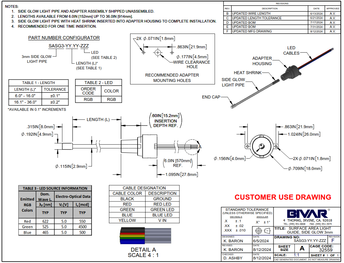
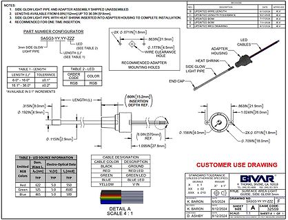
NOTES: 1. SIDE GLOW LIGHT PIPE AND ADAPTER ASSEMBLY SHIPPED UNASSEMBLED. 2. LENGTHS AVAILABLE FROM 6.0IN [152mm] UP TO 36.0IN [914mm]. 3. SIDE GLOW LIGHT PIPE WITH HEAT SHRINK INSERTED INTO ADAPTER HOUSING TO COMPLETE
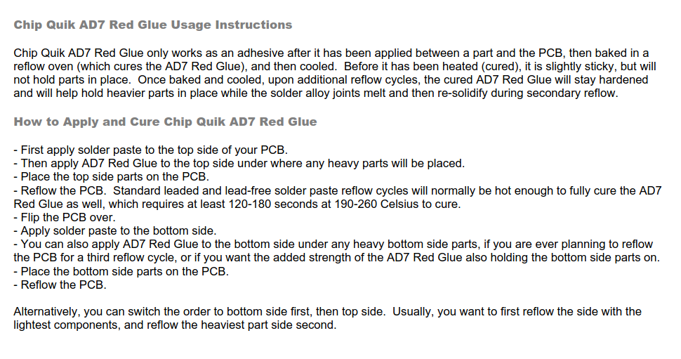
AD7 Red Glue also holding the bottom side parts on.
- Place the bottom side parts on the PCB.
- Reflow the PCB.
Alternatively, you can switch the order to bottom side first, then top side. Usually, you want to first reflow the side with the lightest components, and reflow the heaviest part side second.
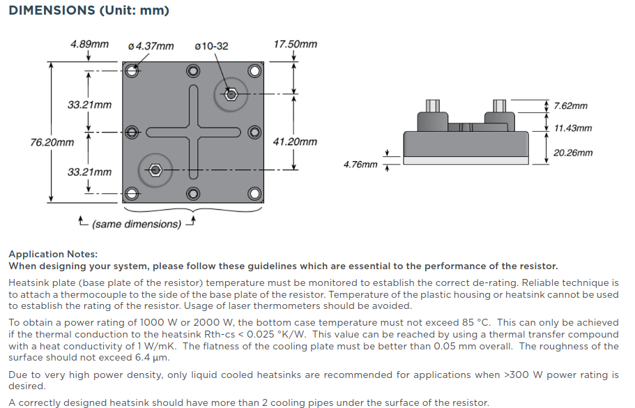
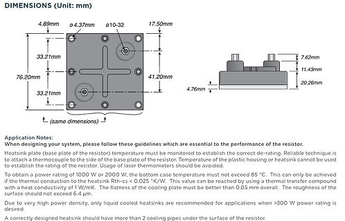
monitored to establish the correct de-rating. Reliable technique is to attach a thermocouple to the side of the base plate of the resistor. Temperature of the plastic housing or heatsink cannot be used to establish the rating of the resistor. Usage of laser thermometers should be avoided.
To obtain a power
body is qualification for passive components marked with the logo, cold resistance value, EL on one side (2)Other resistance values and maximum operating voltages and date code on the opposite side. available on request. Matched resistance values available on request MOUNTING (3)Maximum peak voltages are
deinen N-Kanal auf der High-Side bekommst du nicht ganz durchgesteuert (mess mal den Spannungsabfall am FET), mit dem P-Kanal kannst du sauber schalten. Es gibt auch viele Alternativen <100mOhm, z.B. bei Diodes gucken.
to scroll through the repeatedly to access TREBLE MODE and BASS MODE. Use the ‹/› sources.The left side of the button scrolls down the list that appears in Buttons to change the treble or bass settings, as desired.The display the display; the right side scrolls upward. For direct access to the tuner,
alles Low-Side mit NPN (oder N-MOSFET). Ich denke, das ist bei KFZ der Normalfall. Nur die Beleuchtung ist High-Side geschaltet, aber rein mechanisch, an der Elektronik-Box vorbei. Ich habe früher öfter mal
the module using a circular lens also makes the probe surrounded induction, but the left and right sides still up and down in i i g both directions sensing range, sensitivity, still need to try to install the above requirements. Page 1 of 3 HC-SR501 PIR MOTION DETECTOR Page 2 of 1 working voltage range
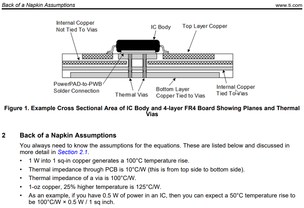
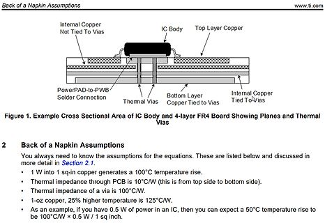
copper generates a 100°C temperature rise.
• Thermal impedance through PCB is 10°C/W (this is from top side to bottom side).
• Thermal impedance of a via is 100°C/W.
• 1-oz copper, 25% higher temperature is 125°C/W.
• As an example, if you have 0.5 W of power in an IC, then you can expect a 50°C temperature
Short Leads 6 +0/−1 C Bulk – Maximum Length Leads 30 +5/−0 A Dimensions – Millimeters FRONT VIEW SIDE VIEW L T H S LL F S T H L F Size Code Nominal Tolerance Nominal Tolerance Nominal Tolerance Nominal Tolerance Nominal Tolerance QM 15.2 ±0.4 7.3 Maximum 13.0 Maximum 18.5 Maximum 0.8 ±0.05 CE 20.3 ±
doch an > Betriebs Reisen: 40º / der einen Seite Puls reisen 400us = Operating Travel: 40°/one side pulse traveling 400us Wenn das PWM Signal 1500us +-500us macht, dann macht das Servo wie beschrieben +-50º Ausschlag (400us = 40º). Das passt zu deiner Beobachtung. Ich würde sagen, falsches
katalog/power-switches-schaltkreise_113433/?params=2613:1492961_integrierten-schaltkreises-art:high-side Wie zu erwarten, erschlägt mich die Vielfalt. Dirk F. schrieb im Beitrag #7726149: > Optokoppler Oh. Ich dacht bisher, das man damit nur LowSide schalten kann. Gibt es da spezielle Optokoppler
Dirk F. schrieb im Beitrag #7726149: >> Optokoppler > Oh. Ich dacht bisher, das man damit nur LowSide schalten kann. Gibt es > da spezielle Optokoppler? Oder ist dies gar nicht nötig? Ein Beispiel > Schaltbild für eine HighSide Schaltung? > Lass die da nichts einreden, Optokoppler verwendet man

 Bild
Bild
 Bild
Bild
 Bild
Bild
 Bild
Bild
 Bild
Bild
 Bild
Bild
 Bild
Bild

 Bild
Bild
 Bild
Bild
 Bild
Bild