-
PDF
150391-da-01-ml-DURCHFLUSSM__G1_8_2XM5_FCH_M_POM_L_de_en.pdf
sinking Durchflussrichtung Flow direction in Pfeilrichtung / at arrow-direction Durchflussbereich L/min. Flow range LPM 0,05 – 3,0 L/ min2(H O bei / at 20°C) Düse Nozzle D= 3,0 mm integriert/ integrated Impulszahl/ Liter Pulses output/ Litre ca. 2.500 Impulse/LiterO 20°C Viskosität der Medien v Viscosity
in „Problem Erfassung Impulse Durchfluss Öl“ · Haus & Smart Home ·
-
PDF
Steuerplattine.pdf
GND 13 T1 L E 14 EN 81 GND (A15)PC7 60 ÄA_L5 15 GND L R/W 16 R/W (A14)PC6 59 ÄA_L4 17 GND L RS 18 RS (A13)PC5 58 ÄA_L3 19 +5V GND 20 (A12)PC4 57 ÄA_L2 5 (A11)PC3 56 ÄA_L1 + (A10)PC2 55 ÄA_S3 GND GND (A9)PC1 54 ÄA_S2
in „AVR MEGA 1280 schaltet sich mit 50Hz an und ab“ · Mikrocontroller und Digitale Elektronik ·
-
PDF
SED1565.pdf
= “L”, D0 to D5 are HZ. D0 to D5 may be “H”, “L” or Open. RD (E) and WR (P/W) are fixed to either “H” or “L”. With serial data input, RAM display data reading is not supported. EPSON 8–21 SED1565 Series Pin
in „Pollin 128x64 GLCD : Bild verzerrt“ · Mikrocontroller und Digitale Elektronik ·
-
PDF
SSD1351-Revision_1.5.pdf
edge of E signal. Table 8-3 : Control pins of 6800 interface Function E R/W# CS# D/C# Write command ↓ L L L Read status ↓ H L L Write data ↓ L L H Read data ↓ H L H (1)e ↓ stands for falling edge of signal (2H stands for HIGH in signal (3L stands for LOW in signal In order to match the operating frequency
in „OLED128x128 SSD1351 RGB Initialisierung Color Farbe bunt SPI 3.3V AVR ATmega8 ATmega328p Assembler“ · Projekte & Code ·
-
PDF
SWKH-Rundschreiben_Nr_1-Hochschulen.pdf
die Bewertung einer Bachelorprüfung zu verpflichten: schule Nach dem Hessischen Hochschulgesetz (§ 91 HHG) erhalte die Hochschule mit der Anerkennung das Klargestellt hat die Judikative schon seit längerem, dass die Anerkennung von privaten Bildungseinrich- Recht, auf privatrechtlicher Grundlage einen
in „Meinungen und Erfahrungen zur Wilhelm Büchner HS“ · Ausbildung, Studium & Beruf ·
-
Datei
Drehzahl-ST.asm
rirechts ; ja -> richtung rechts stellen sbi PORTD, dir ; Pin 2 (Bit3,PortD) = HIGH -> Linkslauf siehe L293D DS ldi wr0, 0x62 ; DS S91 T47 und DS L293 S9 Fig/Tab5 - Turnleft = LOW out TCCR0, wr0 ; COM01 = 1 COM00 = 0 ; -> OCR2 - BOTTOM - CCR0 = LOW -> OCR2 steigend -> länger LOW -> schneller rjmp richteinstend rirechts: cbi PORTD, dir ; Pin 2 = LOW -> Rechtslauf DS von L293D ldi wr0, 0x72 ; DS S91 T47 und DS L293 S9 Fig/Tab5 - Turnright = HIGH out TCCR0, wr0 ; COM01 = 1 COM00 = 1 ; -> OCR2 - Bottom - CCR0 = HIGH -> OCR2 steigend -> länger HIGH -> schneller richteinstend
in „Fehler im ASM-Code zur Motorsteuerung“ · Mikrocontroller und Digitale Elektronik ·
-
PDF
Transistor_2N3904.pdf
transistor 2N3904 PACKAGE OUTLINE Plastic single-ended leaded (through hole) package; 3 leads SOT54 c E d A L b 1 e1 D 2 e 3 b1 L1 0 2.5 5 mm scale DIMENSIONS (mm are the original dimensions) UNIT A b b1 c D d E e e1 L L1(1) 5.2 0.48 0.66 0.45 4.8 1.7 4.2 14.5 mm 5.0 0.40 0.56 0.40 4.4 1.4 3.6 2.54 1.27 12.7
in „12V relais lässt nicht los“ · Analoge Elektronik und Schaltungstechnik ·
-
PDF
BD139-16.pdf
single-ended leaded (through hole) package; mountable to heatsink, 1 mounting hole; 3 leads SOT32 E A P 1 P D L1 L 1 2 3 bp w M c e1 Q e 0 2.5 5 mm scale DIMENSIONS (mm are the original dimensions) UNIT b c D E e e L L1(1) Q P P w A p 1 max 1 mm 2.7 0.88 0.60 11.1 7.8 4.58 2.29 16.5 2.54 1.5 3.2 3.9 0.254 2.3
in „Transistor als Schalter (BD139) richtig auslegen“ · Mikrocontroller und Digitale Elektronik ·
-
PDF
bd139.pdf
single-ended leaded (through hole) package; mountable to heatsink, 1 mounting hole; 3 leads SOT32 E A P 1 P D L1 L 1 2 3 bp w M c e1 Q e 0 2.5 5 mm scale DIMENSIONS (mm are the original dimensions) UNIT b c D E e e L L1(1) Q P P w A p 1 max 1 mm 2.7 0.88 0.60 11.1 7.8 4.58 2.29 16.5 2.54 1.5 3.2 3.9 0.254 2.3
in „Basisvorwiderstand Berechung beim BD139 richtig?“ · Mikrocontroller und Digitale Elektronik ·
-
PDF
BC337_3.pdf
transistor BC337 PACKAGE OUTLINE Plastic single-ended leaded (through hole) package; 3 leads SOT54 c E d A L b 1 e1 D 2 e 3 b1 L1 0 2.5 5 mm scale DIMENSIONS (mm are the original dimensions) UNIT A b b1 c D d E e e1 L L1(1) 5.2 0.48 0.66 0.45 4.8 1.7 4.2 14.5 mm 5.0 0.40 0.56 0.40 4.4 1.4 3.6 2.54 1.27 12.7
in „Stromverstärkung mit Transistor; Arduino“ · Analoge Elektronik und Schaltungstechnik ·
-
PDF
datasheet.pdf
transistor BC337 PACKAGE OUTLINE Plastic single-ended leaded (through hole) package; 3 leads SOT54 c E d A L b 1 e1 D 2 e 3 b1 L1 0 2.5 5 mm scale DIMENSIONS (mm are the original dimensions) UNIT A b b1 c D d E e e1 L L1(1) 5.2 0.48 0.66 0.45 4.8 1.7 4.2 14.5 mm 5.0 0.40 0.56 0.40 4.4 1.4 3.6 2.54 1.27 12.7
in „Dimensionierung der Transistorschaltung“ · Analoge Elektronik und Schaltungstechnik ·
-
PDF
BC337_3.pdf
transistor BC337 PACKAGE OUTLINE Plastic single-ended leaded (through hole) package; 3 leads SOT54 c E d A L b 1 e1 D 2 e 3 b1 L1 0 2.5 5 mm scale DIMENSIONS (mm are the original dimensions) UNIT A b b1 c D d E e e1 L L1(1) 5.2 0.48 0.66 0.45 4.8 1.7 4.2 14.5 mm 5.0 0.40 0.56 0.40 4.4 1.4 3.6 2.54 1.27 12.7
in „Transistor für Bewegungsmelder“ · Analoge Elektronik und Schaltungstechnik ·
-
PDF
BD329.PDF
single-ended leaded (through hole) package; mountable to heatsink, 1 mounting hole; 3 leads SOT32 E A P 1 P D L1 L 1 2 3 w M c e1 Q e 0 2.5 5 mm scale DIMENSIONS (mm are the original dimensions) UNIT b c D E e e L L1(1) Q P P w A p 1 max 1 mm 2.7 0.88 0.60 11.1 7.8 4.58 2.29 16.5 2.54 1.5 3.2 3.9 0.254 2.3 0.65
-
PDF
1.5KE6V8A.PDF
78.80 1.0 5.0 103.0 14.6 0.105 1.5KE82A 1.5KE82CA 70.10 77.90 86.10 1.0 5.0 113.0 13.3 0.105 1.5KE91A 1.5KE91CA 77.80 86.50 95.50 1.0 5.0 125.0 12.0 0.106 1.5KE100A 1.5KE100CA 85.50 95.00 105.00 1.0 5.0 137.0 11.0 0.106 1.5KE110A 1.5KE110CA 94.00 105.00 116.00 1.0 5.0 152.0 9.9 0.107 1.5KE120A 1.5KE120CA
in „Welches Bauteil (Diode?) ist das?“ · Analoge Elektronik und Schaltungstechnik ·
-
 Bild
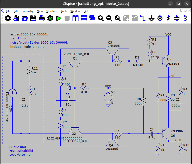
LTspice Schaltplan einer Schaltung
tran 10ms .noise V(out) I1 dec 1000 10k 30000k .include modelle_rb.lib 2SC1815GR_B Q1 R11 5m R1 100 L3 56p C3 2.8p C1 10u L4 56u R2 100 Q2 2SC1815GR_B L1C1-GRN1000000000 2N3906 Q3 R6 110 D2 1N4148 Q5 2N3904 VCC R5 91 L7 2.2u R9 910 V1 5 VE6 R18 680 R3 22 C2 100 Q6 2N3906 OUT R19 1k R10 75 R4 100 C4 4.7u
in „Kleine aktive Magnetloop-Breitbandantenne“ · HF, Funk und Felder · · Screenshots
-
PDF
tmp95fy64f.pdf
access by internal CPU Block address Address area Size A17 A16 A15 A14 A13 Single chip Single boot BA0 L L x x x FC0000H - FCFFFFH 010000H - 01FFFFH 64K byte BA1 L H x x x FD0000H - FDFFFFH 020000H - 02FFFFH 64K byte BA2 H L x x x FE0000H - FEFFFFH 030000H - 03FFFFH 64K byte BA3 H H L x x FF0000H - FF7FFFH 040000H - 047FFFH 32K byte BA4 H H H L L FF8000H - FF9FFFH 048000H - 049FFFH 8K byte BA5 H H H L H FFA000H - FFBFFFH 04A000H - 04BFFFH 8K byte BA6 H H H H x FFC000H - FFFFFFH 04C000H - 04FFFFH 16K byte 95fy64_10e.doc 12 99/01/19 11:43 TOSHIBA
in „[S] Tools für TMP95FY64F von Toshiba“ · Mikrocontroller und Digitale Elektronik ·
-
Datei
DG24128.asm
------------------------------------------------ .equ LCD_C_PORT = PORTD .equ LCD_RE = PD3 ; Reset L .equ LCD_CD = PD4 ; Code/Data H/L .equ LCD_CE = PD5 ; Enable L .equ LCD_WR = PD6 ; Write L .equ LCD_RD = PD7 ; Read L .equ LCD_D_OUT = PORTA .equ LCD_D_IN = PINA .equ LCD_D_DIR = DDRA ;--- lower Register
-
PDF
ag172d.pdf
25V L902 073G 174 65 H LINE FILTER L902 073G 174 65 LS LINE FILTER BY LISHIN L901 073G 174 76 L CHOKE COIL LI TAI LF-002923 L921 073G 253 91 H CHOKE COIL L922 073G 253 91 H CHOKE COIL L921 073G 253 91 S CHOKE COIL L922 073G 253 91 S CHOKE COIL T901 080GL17T 33 N POWER X'FMR T901 080GL17T 33 T XFMR FOR POWER TDK PT801 080GL17T 36 DN XFMR FOR POWER DARFON 47 Downloaded from www.Manualslib.com manuals search engine
in „Geplatzte 25V-Elkos im 12V-Netzteil gegen 16V Low ESR austauschen?“ · Analoge Elektronik und Schaltungstechnik ·
-
Datei
Ampel3.a51
anl A,#03h jnz GELB1 mov P5,#52h mov R0,#30 lcall wait pop 0F8h sjmp LOOP wait: push ACC push PSW L2: mov R4,#100 L0: mov R1,#255 L1: djnz R1,L1 djnz R4,L0 djnz R0,L2 pop PSW pop ACC reti ME1: setb M1 reti ME2: setb M2 reti CSEG at 4300h ZK0: db 34h,50,54h,30,94h,50,8Ch,50,94h,30,0d4h,10,34h,10 ZK1: db 34h,50,54h,30,94h,50,96h,10,91h,50,92h,30,94h,20,0d4h,10,34h,20 end
in „µController der eine Ampel steuert“ · Mikrocontroller und Digitale Elektronik ·
-
PDF
messungunrouted.pdf
C4066D R34 I C59 3 1 C E 6 L 2 TP45 R31 5 R33 R 3 R32 N R 0 2 TP47 3 0 R1 LED5 C P - LED6 R3 2 R16 5 C LED4 A C I M CI E M TP91 R14 C14 R11 R13 1 TP93 R 4 C I4066D 2 1 R19 X C TP92 R10 R65 C34 C13 R8 R9 R64 2 N 1 0 2 R66 TP94 R
in „Cadsoft Eagle“ · Platinen ·
-
PDF
LM334.pdf
einem einzigen, als nicht- rekt an einen Spannungsteiler und, was am wichtigsten ist, direkt an die lN-LO- bezie invertierender Verstärker ge- mit hoher lmpedanz ange- er nimmt nur sehr wenig hungsweise lN-Hl-Eingäng, schalteten Opamp aufgebaut schlossen werden und benö- Strom auf. Außerdem gibt es gewöhnlicher DVM-lCs wir 28 Elekto r 7-Bl9 t, ui
in „Präzise Temperaturmessung mit langer Leitung“ · Analoge Elektronik und Schaltungstechnik ·
-
PDF
MAX1647.PDF
Respect to CCI 4 TRIP POINTS AND LINEAR CURRENT SOURCES 8 BATT POWER_FAIL Trip Point MAX1647 86.5 89 91.5 % of VDCIN THM THERMISTOR_OR % of Over-Range Trip Point MAX1647 89.5 91 92.5 V REF THM THERMISTOR_COLD % of Trip Point 74 75.5 77 VREF THM THERMISTOR_HOT 22 23.5 25 % of Trip Point VREF THM THERMISTOR_UR
in „Win98 Diagnose Notebook Akku immer 50%“ · PC Hard- und Software ·
-
PDF
MAX1647_1_.PDF
Respect to CCI 4 TRIP POINTS AND LINEAR CURRENT SOURCES 8 BATT POWER_FAIL Trip Point MAX1647 86.5 89 91.5 % of VDCIN THM THERMISTOR_OR % of Over-Range Trip Point MAX1647 89.5 91 92.5 V REF THM THERMISTOR_COLD % of Trip Point 74 75.5 77 VREF THM THERMISTOR_HOT 22 23.5 25 % of Trip Point VREF THM THERMISTOR_UR
-
 Bild
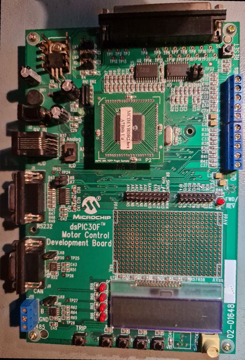
dsPIC30F Motor Control Development Board
MC9DEVBR2.14 A7B6h L4 TP1 TP2 TP3 TP4 TP5 TP6 TP7 TP8 TP9 TP10 TP11 TP12 TP13 TP14 TP15 R1 R2 R3 R4 R5 R6 R7 R8 R9 R10 R11 R12 R13 R14 R15 R16 R17 R18 R19 R20 R21 R22 R23 R24 R25 R26 R27 R28 R29 R30 R31 R32 R33 R34 R35 R36
in „[V] ältere Demoboards PIC, NEC und Motor“ · Markt · · Platinenfotos
-
PDF
18F27J13.pdf
1 D 1 2 R R / S S / O I C/ 1 N 1 / / / / E / I O S S /1 J G 1PJ N N N N O N L L 1 1 N C 2 D L / / / / C / / / / / / / 8 N 1 C A A A A D A S A A C C C C 1 7C 8C 9C G 0 3 $ M R R R R V R V R R R R R R I R 3 U P n001 n001 n001 2 0 1 2 3 4 5 6 7 8 91 1 1 1 1 C 1 V3, 3 N N 4 D G 0
in „ENC28j60, PIC18F27J13, POE, Webserver“ · Mikrocontroller und Digitale Elektronik ·
-
PDF
PK566-NB.pdf
Selection D3 D2 D1 D0 Step Angle D3 D2 D1 D0 Step Angle (Divisions/Step) (Divisions/Step) H H H H 0.72˃ L H H H 0.0288˃ (1) (25) H H H L 0.36˃ L H H L 0.018˃ (2) (40) H H L H 0.288˃ L H L H 0.0144˃ (2.5) (50) H H L L 0.18˃ L H L L 0.009˃ (4) (80) H L H H 0.144˃ L L H H 0.0072˃ (5) (100) H L H L L L H L 0.09˃ 0.00576˃ (8) (125) H L L H 0.072˃ L L L H 0.0036˃ (10) (200) H L L L 0.036˃ L L L L 0.00288˃ (20) (250) Switching while in pulse input mode may cause the motor to slip position. Figure 10 illustrates switching the step angle
in „Hitzeprobleme beim L298 !?“ · Mikrocontroller und Digitale Elektronik ·
-
PDF
MGA-62563__AV02-1237EN_.pdf
Freq. S11 S21 S12 S22 K-factor GHz Mag. Ang. dB Mag. Ang. Mag. Ang. Mag. Ang. 0.1 0.185 -82.272 22.91 13.982 155.827 0.042 5.4 0.129 -164.437 1.09 0.2 0.187 -90.11 22.63 13.537 153.346 0.042 5.474 0.135 -168.363 1.1 0.3 0.193 -98.147 22.31 13.054 150.578 0.042 5.636 0.141 -172.09 1.12 0.4 0.203 -106.14
-
PDF
E_Grad_kpl.pdf
of Wisconsin – Extension, Department of Engineering and Applied Science. 4. William L. Wolfe: Handbook of Military Infrared Technology, Office of Naval Research, Department of Navy, Washington, D.C. 5. Jones, Smith, Probert: External thermography of buildings..., Proc. of the Society
-
 Bild
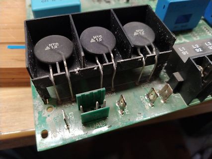
Nahaufnahme von NTC-Thermistoren auf einer Leiterplatte
NTC 1,0 NTC 1,0 NTC 1,0 L1 91 L2 92 L3 9 R303 R305 R302 R304 R303 UAC
in „Danfoss FU VLT 3006 Tod“ · Analoge Elektronik und Schaltungstechnik · · Platinenfotos
-
Datei
DELL_1wire_Emulator_Tiny85V.bas
*********************************** Mainloop: Waitreset: Disable Interrupts Timer_t0 = 0 Waitfall: L1: sbis pinb, DqPin rjmp L1 L2: sbic pinb, DqPin rjmp L2 Start Timer0 Rwaitrise: L01: sbic pinb, DqPin rjmp L01 L02: sbis pinb, DqPin rjmp L02 Stop Timer0 If Timer_t0 < T1reset Then Goto Waitreset If
in „1-Wire OW-wire slave device <=4MHz low current AVR assembler ATmega8“ · Projekte & Code ·
-
PDF
butterfly.pdf
6 2 2 5 8 2 2 7 1 2 2 C 5 M D D D D D D D D D D D D D D D 1 5 C L L L L L L L L L L L L L L L V 9 1 G D C 0 8 7 6 5 4 3 2 1 0 9 8 7 6 5 4 3 E G V 1 4 4 4 4 4 4 4 4 4 3 3 3 3 3 3 3 T R U A X A A A A A G C C C C C C C C G G V P P P P P P P P P P P P P P P P 6 3 0 1 2
in „AVR Butterfly, was benötigt?“ · Mikrocontroller und Digitale Elektronik ·
-
 Bild
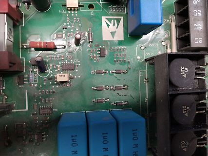
Nahaufnahme einer Leiterplatte mit elektronischen Bauteilen
ICH V3 R300 R302 L1 L2 L3 91 92 93 C18 1K50 R23 TR1 IC1 140 M NTC 1,0
in „Danfoss FU VLT 3006 Tod“ · Analoge Elektronik und Schaltungstechnik · · Platinenfotos
-
PDF
84123_usb_i2c_km-2.pdf
kurzes Makro für solch eine Daten- Wert 3: FF; loggerfunktion lautet z. B. folgendermaßen: S90 05 R04 L0200 >00 Beispiel:D/A-WandlermitPCF8591 Soll mit der vorgestellten Beispielschaltung eine analoge Die Erläuterung hierzu: Spannung auf den D/A-Wandler-Ausgang (A OUT) ausgegeben S 90 05 R 04 L 02 00 >
in „Hygrosens I2C Tmp Modul antwortet nicht“ · Mikrocontroller und Digitale Elektronik ·
-
PDF
TF5000CI.pdf
L78L06CD L78L06CZ 6 V L78L06AC L78L06ACD L78L06ACZ L78L06ACUTR 6 V L78L06AB L78L06ABD L78L06ABZ L78L06ABUTR 6 V L78L08C L78L08CD L78L08CZ 8 V L78L08AC L78L08ACD L78L08ACZ L78L08ACUTR 8 V L78L08AB L78L08ABD
in „CPU SAA7219 per Jtag auf Basis FT2232H ansprechen - Tool schreiben“ · PC Hard- und Software ·
-
PDF
lowpassO.pdf
D5 1 2 0 0 D4 7 R C 2 e maN 2 5 SV2 D1 R 3 4 3 R e L16 e 1 9 9 C C C 2 m m 7 R22 CC C R 0 2 R L20 N N 1 K I 2 C C X R31 C66R21 R Name D2 C 1 1 e e C e C e e e a a a a a a N N N 62C 03CN 13C 53CN 22C 328N4K 2C 2 2K 7C 3 1K 31C 5 3K C32 5K 6K C21 C C3 C
in „HF (UKW) Layout“ · Platinen ·
-
PDF
lowpassU.pdf
D5 1 2 0 0 D4 7 R C 2 e maN 2 5 SV2 D1 R 3 4 3 R e L16 e 1 9 9 C C C 2 m m 7 R22 CC C R 0 2 R L20 N N 1 K I 2 C C X R31 C66R21 R Name D2 C 1 1 e e C e C e e e a a a a a a N N N 62C 03CN 13C 53CN 22C 328N4K 2C 2 2K 7C 3 1K 31C 5 3K C32 5K 6K C21 C C3 C
in „HF (UKW) Layout“ · Platinen ·
-
PDF
AMN1_MP_Motion_Sensor.pdf
) (Max.) 2. Movement speed • Standard detection type/Spot detection type/ Horizontal*Remark 2 100° 91° 38° 110° • Slight motion detection type: 0.5 m/s DetectionVertical*emark 2 82° 91° 22° 93° 3. Detection object = human body (size is 700mm × 250mm range Remark 3 27.559inch × 9.843inch, but for the
in „AMN1 Motion Sensor, woher kriegt man ihn?“ · Mikrocontroller und Digitale Elektronik ·
-
PDF
AMN1_MP_Motion_Sensor.pdf
) (Max.) 2. Movement speed • Standard detection type/Spot detection type/ Horizontal*Remark 2 100° 91° 38° 110° • Slight motion detection type: 0.5 m/s DetectionVertical*emark 2 82° 91° 22° 93° 3. Detection object = human body (size is 700mm × 250mm range Remark 3 27.559inch × 9.843inch, but for the
in „Motion Sensor Analog oder Digital“ · Mikrocontroller und Digitale Elektronik ·
-
PDF
Transistortester092k.pdf
Kapazitätsmessungen dargestellt. 2. Vergleich der 680Ω Widerstände. Dargestellt wird in Zeile 1 der kryptische Text „L1+2- .3- 2+.“. Das soll Folgendes bedeuten: Das L steht für Low also die 680Ω Widerstände. 1+ steht dafür das der Widerstand von Pin1 nach + (VCC) geschaltet wird. Das nachfolgende 2- steht für die Schaltung
-
PDF
IR_Sensor.pdf
) (Max.) 2. Movement speed • Standard detection type/Spot detection type/ Horizontal*Remark 2 100° 91° 38° 110° • Slight motion detection type: 0.5 m/s DetectionVertical*emark 2 82° 91° 22° 93° 3. Detection object = human body (size is 700mm × 250mm range Remark 3 27.559inch × 9.843inch, but for the
in „Bewegungsmelder Plastikkappe direkt auf dem PIR-Sensor“ · Haus & Smart Home ·
-
PDF
GX25_Daten.pdf
brouillard d’huile par t la pression du carter inférieur r c e Engine oil capacity 0.08 l Capacité d’huile moteur 0.08 l L Dimensions (L x W x H) 192 x 221 x 230 mm Dimensions (L x l x H) 192 x 221 x 230 mm Dry weight 2.78 kg* *w/o clutch Poids à sec 2.78 kg* *sans embrayage Spezifikationen
in „Warum sind Brushlessmotoren so klein??“ · Analoge Elektronik und Schaltungstechnik ·
-
PDF
GWM120-0075P3.pdf
= 75 V with Trench MOSFETs ID25 = 125 A in DCB isolated high current package R DSon typ. = 3.7 m Ω L+ P is Gate G3 G1 G5 S3 S5 S1 L1 L2 L3 G4 G6 G2 ns S4 S6 P owerP i S2 L - Applications MOSFETs AC drives Symbol Conditions Maximum Ratings • in automobiles V T = 25°C to 150°C 75 V -electric power steering
in „Umrichter für E-Kart Anwendung 60V / 120A“ · Mikrocontroller und Digitale Elektronik ·
-
PDF
Audio_Verstaerker_1.pdf
133 C19 1n BZX84C18VL 18V Potentiometer R76 Clarostat 250R 0R22 T3 6502 R88 Q18 2N2907 125 R83 R81 L2 M7 R17 IRFP240 1K21 R89 100R 22R1 125 R77 0R47 D5 V4 T1 6502 Q3 2N2222 BZX84C6V8L V1 R67 R66 6,8V Potentiometer R70 82 2SA1837Q21 Clarostat 250R 62 47R5 22K1 0R22 R86 R18 125 R82 R75 L1 M3 121 IRFP240
in „Reverse Engineering eines Audio verstärkers“ · Analoge Elektronik und Schaltungstechnik ·
-
PDF
gesamtinhalt-1967-2019_Call_Heft.pdf
GLONASS Ergänzungen und Bemerkungen zum Artikel: Ein sehr rauscharmer Anten- nenverstärker für das L-Band ( aus Heft 3/91) Matjaz Vidmar S 53 MV 1994/2 110…111 GPS & GLONASS Ergänzungen und Bemerkungen zum Artikel: Ein sehr rauscharmer Anten- Matjaz Vidmar S 53 MV 1994/2 110…111 Änderungen nenverstärker für das L-Band ( aus Heft 3/91) Selbstbau eines Empfängers für GPS & GLONASS Teil V Matjaz Vidmar S 53 MV 1994/2 112…123 GPS & GLONASS Selbstbau eines Empfängers für GPS & GLONASS Teil VI Matjaz Vidmar S 53 MV
-
PDF
STM32F4-BASEbrd.pdf
4 2 71R C23X1 JP5 w o 3 4 4 w 3 4 5 C C R 02R R2 1 P J X W R R R D R 81R 1 C6 C C J C26 s o 1 1 6 91R L 87 C93 R15 s D D Di C R R C . E E Em D 72C R1 C2 e L L L S 1 SV2 20 1 SV3 10 01.03.2012 18:44:54 C:\Users\SuperK\13-Eagle\1-Projekte\STM32F407Vx_Baseboard\STM32F4-BASE.brd
in „STM32F407 (100pin) Basisboard - Review bitte“ · Mikrocontroller und Digitale Elektronik ·
-
PDF
fcc_9.pdf
Item –EUT Test Photos. 3.1.3 DEVIATION FROM TEST STANDARD No deviation 3.1.4 TEST SETUP V e rtic a l R e fe re n c e G ro u n d P la n e Te s t R e c e iv e r E U T 4 0 c m 8 0 c m L IS N H o riz o n ta l R e fe re n c e G ro u n d P la n e N o te : 1 .S u p p o rt u n its w e re c o n n e c te d to s e c o n d L IS N . 2 .B o th o f L IS N s (A M N ) a re 8 0 c m fro m E U T a n d a t le a s t 8 0 fro m o th e r u n its a n d o th e r m e ta l p la n e s 3.1.5 EUT OPERATING CONDITIONS The EUT was configured
in „Wlan2Serial Modul für 5 euro“ · Mikrocontroller und Digitale Elektronik ·
-
PDF
TARGET__HiQTRX_V24S_Circuit.pdf
5V 0 0 0 0 0 2 0 0 0 0 0 4 4 4 5 D I I I T I I I I I I 5 I D I T D I I I I I I I 7 6 5 K E 6 0 D 1 L I I I I T I D I I I I 6 I D O T D O O 2 2 2 R 2 2 1 2 1 2 1 2 1 2 1 L A A I N I I N I N L L L L N I E N E E I N I N I I N I I A A L K L D C C G C C G C G C C C C D C S G S S C G C G C G C D P / _ G V
-
 Bild
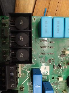
Nahaufnahme einer Leiterplatte mit Kondensatoren und NTC-Bauteilen
NTC 1,0 MK303 MK304 MK302 6H 0H1 6H 0H1 L1 91 L2 92 L3 93 94 P1 R301 W2 IC3 IC4 C18 K30
in „Danfoss FU VLT 3006 Tod“ · Analoge Elektronik und Schaltungstechnik · · Platinenfotos
-
PDF
PS9530_KM_G_071030.pdf
Altgeräte über die örtlichen Sammelstellen für Elektronik-Altgeräte zu entsorgen!k- ELVTelefon 04 91/600 888 • Telefax 04 91/6008-244 ELVjournal 4/00 1 Bau- und Bedienungsanleitung Prozessor-Netzteil PS 9530 Das neue Prozessor-Netzteil PS 9530 im soliden Metallgehäuse gehört in die Spitzen-klasse der
in „ELV Netzteil "PS 9530" 0-30V/0-10A - Erfahrungen“ · Mikrocontroller und Digitale Elektronik ·