-
PDF
mmds.pdf
a high flexibility for future add-ons. The following components are proposed: Power (1 a,b,c)GND (32 a,b,c) VCC This is given by the board design since 1 a,b,c and 32 a,b,c are each shortened. (31 a,c) Special voltage (I.e. +15V) (30 a,c) Special voltage (I.e. -15V) Communication (2 a c) RS485 (3 a
in „Modulares Mikrocontroller System“ · Mikrocontroller und Digitale Elektronik ·
-
Datei
Schrittmotor.asm
DEZ_ASC5 ;Dezimalwert spiegeln call ASC_DEZ ;ASCCII in Hex wandeln 10Byte SRAM Dezwert nach R20...R23 = 32Bit Hex -- R20=L R23=H -- Dezwert=L Dezwert+10=H clr AL lds AH, PM sbrc AH, 0 rjmp PosR ;minusbereich clr AH ori R23, 0b10000000 ;pos. Wert sub R20, R12 ;errechne Dif. zu ist sbc R21, R13 sbc R22, R14
in „Spielerei mit einem 2- und 5-Phasen-Schrittmotor“ · Projekte & Code ·
-
Datei
mpx_2digit_ntc.c
------------------------------------------------------------ */ #include <util/delay.h> #include <avr/io.h> #include <avr/pgmspace.h> #include <avr/interrupt.h> #include "adc_single.h" #include "mpx_2conc.h" /* ATtiny 24 / 44 / 84 Anschlusspins IC +-----------+ Vcc | 1 A 14 | GND PB0 - PCINT8 - XTAL1
in „7 Segment Anzeige auf verschiedenen Ports“ · Mikrocontroller und Digitale Elektronik ·
-
Datei
BelTimer_V2_02.07.10_21-46.c
links, [5] auslösen/starten/ok Erik Herkenrath (01.07.2010 begonnen) */ //Header-Dateien #include <avr/io.h> #include <stdint.h> #include "LCD/lcd.h" #include <stdlib.h> #include <avr/interrupt.h> //#include <util/delay.h> //nur falls delays verwendet werden //#include <avr/pgmspace.h> //nur falls Zugriff
in „Wie Arbeitstakte des Prozessors zählen?“ · Mikrocontroller und Digitale Elektronik ·
-
PDF
Chip_-_Infosheet.pdf
By cIosing jumper J1 a manual reset can be triggered. System Cloek - The CPU dock is generated by a 14.7456MHz erystal (Xl) for error free common baudrates. An additional 32.768kHz asynchronous timer crystal can be used for asoftware realtime ~ rial Port - True RS232 level signals are provided by the
in „12 Led's mit C++ ansprechen atmega128“ · Softwareentwicklung ·
-
PDF
Chip_-_Infosheet.pdf
By cIosing jumper J1 a manual reset can be triggered. System Cloek - The CPU dock is generated by a 14.7456MHz erystal (Xl) for error free common baudrates. An additional 32.768kHz asynchronous timer crystal can be used for asoftware realtime ~ rial Port - True RS232 level signals are provided by the
-
Datei
tft_data.c
136, 245, 55, 2, 43, 97, 246, 196, 168, 31, 69, 230, 90, 67, 107, 75, 176, 138, 164, 27, 205, 154, 32, 143, 157, 12, 101, 71, 140, 159, 141, 24, 14, 45, 45, 116, 93, 197, 215, 209, 104, 14, 103, 101, 171, 233, 204, 108, 59, 242, 140, 199, 170, 121, 124, 60, 157, 12, 36, 225, 249, 54, 35, 134, 92, 77,
-
Datei
TECHLIB_APR07_Dir.txt
AVR_ICEPRO_IO_doc.pdf 12.03.2007 16:38 702.478 AVR_Instruction_set.pdf 12.03.2007 16:37 14.198 AVR000.pdf 12.03.2007 16:37 78.501 AVR001.pdf 12.03.2007 16:37 350.457 AVR030.pdf 12.03.2007 16:37 128.488
in „STK500 CD ISO Image“ · Mikrocontroller und Digitale Elektronik ·
-
Datei
irsnd.c
# endif // IRSND_OCx #elif defined (__AVR_ATmega16__) || defined (__AVR_ATmega32__) // ATmega16|32 uses OC2 = PD7 # if IRSND_OCx == IRSND_OC2 // OC2 # define IRSND_PORT_LETTER D # define IRSND_BIT_NUMBER 7 # else # error Wrong value for IRSND_OCx
in „IRMP - Infrared Multi Protocol Decoder“ · Projekte & Code ·
-
Datei
irsnd.c
# endif // IRSND_OCx #elif defined (__AVR_ATmega16__) || defined (__AVR_ATmega32__) // ATmega16|32 uses OC2 = PD7 # if IRSND_OCx == IRSND_OC2 // OC2 # define IRSND_PORT_LETTER D # define IRSND_BIT_NUMBER 7 # else # error Wrong value for IRSND_OCx
in „IRMP - Infrared Multi Protocol Decoder“ · Projekte & Code ·
-
 Bild
Bild
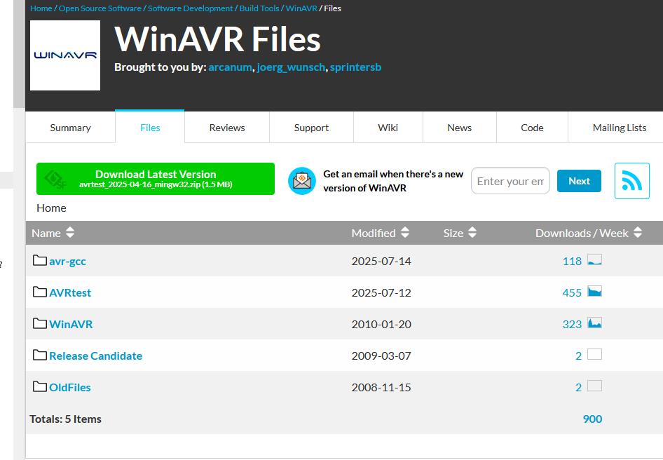
WinAVR Files Download-Seite
WinAVR Files Brought to you by: arcanum, joerg_wunsch, sprintersb Summary Files Reviews Support Wiki News Code Mailing Lists Download Latest Version avrtest_2025-04-16_mingw32.zip (1.5 MB) Get an email when there's a new version of WinAVR Next Home Name Modified Size Downloads / Week avr-gcc 2025-07-14 118 AVRtest 2025-07-12 455 WinAVR 2010-01-20 323 Release Candidate 2009-03-07 2 OldFiles 2008-11-15 2 Totals: 5 Items 900
in „WinAVR für ATmega328PB“ · Mikrocontroller und Digitale Elektronik · · Screenshots
-
Datei
BCM.S
inspiriert vom Thread "24fach 16Bit BCM logarithmisch" auf ledstyles.de, Original von bkwei * */ #include "avr/io.h" #define BITCOUNT 14 ; Bittiefe der PWM 10-16 #define MAXLIGHT 255 ; Masterhelligkeit 0-255 (kann an Adresse aMaster jederzeit geaendert werden) // MACROS Zeitschleifen .macro nops82 ; Macro Zeitschleife
in „Bit Angle Modulation Probleme“ · Mikrocontroller und Digitale Elektronik ·
-
Datei
update.php
MCU-Webserver # geändert am: 28.02.2010 # ----------------------------------------------------- /* Ausgabe vom AVR-NET-IO: webpage.h -> daten.html // AD-Werte "CO2=%VA@04\r\n" "Temperatur=%VA@05\r\n" "Luftfeuchte=%VA@06\r\n" "AD3=%VA@07\r\n" "PORTA=%VA@11\r\n" "PORTB=%VA@12\r\n" "PORTC=%VA@13\r\n" "PORTD=%VA@14\
-
Datei
ATB_Touch_Prg_1.c
I2C, P92 - AT42QT1070 // P30 - Board 1 mit AT1284p, NT2 mit 5/12V 3A #include <stdbool.h> #include <avr/pgmspace.h> #include "main.h" #include <util/delay.h> #include "i2clcd.h" #include "i2cmaster.h" #include "avr/io.h" #include "util/delay.h" #include "avr/interrupt.h" #include <stdlib.h> int8_t d;
in „AT42QT1070 - QTouch für das Modulare Board“ · Mikrocontroller und Digitale Elektronik ·
-
Datei
main.cpp
PLL_fuer_Landolt.cpp * * DDS Code von S.Landolt * * Created: 12.03.2021 * Author : Devil-Elec * Code angepasst für AVR128DB48 mit TCD0 und PLL * Board: AVR128DB48 Curiosity Nano * * Ausgangspin: PA5 */ // #define TIMERTAKT_PLL // für 48MHz PLL Takt "einkommentieren" #include <avr/io.h> #include <avr/pgmspace.h> void
in „Attiny2313 Timer16 Bit, Normal Mode, unsauber“ · Mikrocontroller und Digitale Elektronik ·
-
Datei
swdisplay_nokia.h
0x1E }, // 9 { 0x00, 0x36, 0x36, 0x00, 0x00 }, // : { 0x00, 0x56, 0x36, 0x00, 0x00 }, // ; { 0x08, 0x14, 0x22, 0x41, 0x00 }, // < { 0x14, 0x14, 0x14, 0x14, 0x14 }, // = { 0x00, 0x41, 0x22, 0x14, 0x08 }, // > { 0x02, 0x01, 0x51, 0x09, 0x06 }, // ? { 0x32, 0x49, 0x59, 0x51, 0x3E }, // @ { 0x7E, 0x11, 0x11
in „Nokia 5110 LCD defekt ?“ · Mikrocontroller und Digitale Elektronik ·
-
Datei
lcd.c
0 // |nc|EN|RW|RS| |d|d|d|d // //!!!!!!!!!!!!!!!!!!!!!!!!!!!kontrolieren ob text im rom #include <avr/io.h> #include <stdio.h> #include <stdlib.h> #include <inttypes.h> #include <avr/pgmspace.h> #include "/home/tom/cprog/avr/tools/ch2a/convert_hex2asci.c" #define CPU_CLK 800000 //cpu CLK in KHz *10
-
PDF
assembler_beginner.pdf
erscheinen, und • rechts unten ein weiteres Feld, in dem diverse Werte beim Entwanzen angezeigt werden. Avr-Asm-Tutorial 14 http://www.avr-asm-tutorial.net Alle Fenster sind in Größe und Lage verschiebbar. Für den Nachvollzug der nächsten Schritte im Studio ist es notwendig, das im Editorfenster sichtbare
in „Assembler Tutorial als PDF ?“ · Mikrocontroller und Digitale Elektronik ·
-
Datei
main.c
/* * Schattenbahnhofsteuerung * main.c * * Created: 27.06.2011 14:23:14 * Author: Christian Flach */ #include <avr/io.h> #include <stdint.h> #include <avr/sleep.h> #include <stdlib.h> #define F_CPU 1000000UL #include <util/delay.h> #include <string.h> /*UART*/ #include <avr/interrupt.h> #include <avr/pgmspace.h> #include <avr/signal.h> #include <cmf/uart.c> #define UART_BAUD_RATE 4800 /*Ende UART*/ /*PROGRAMMTEILE**************/ #define SENDEERRORS 1 #define SENDESCHRITTE
in „Flash Speicher sparen“ · Mikrocontroller und Digitale Elektronik ·
-
Datei
avr_test3.c
0x3e,0x51,0x49,0x45,0x3e, // 30 0 0x00,0x42,0x7f,0x40,0x00, // 31 1 0x42,0x61,0x51,0x49,0x46, // 32 2 0x21,0x41,0x45,0x4b,0x31, // 33 3 0x18,0x14,0x12,0x7f,0x10, // 34 4 0x27,0x45,0x45,0x45,0x39, // 35 5 0x3c,0x4a,0x49,0x49,0x30, // 36 6 0x01,0x71,0x09,0x05,0x03, // 37 7 0x36,0x49,0x49,0x49,0x36, /
in „Problem mit Nokia 3310 Display an ATtiny2313“ · Mikrocontroller und Digitale Elektronik ·
-
Datei
nixieclock.c
//DCF Uhr mit 6* Nixie //Oktober 2010 //Header Dateien #include <avr/io.h> #include <avr/interrupt.h> #include <stdlib.h> #define F_CPU 8000000 ///////////// //Variablen// ///////////// //date uint8_t week_day; uint8_t day; uint8_t month; uint16_t year; //time uint16
in „AVR - Conrad DCF Modul - Pegel zu niedrig“ · Mikrocontroller und Digitale Elektronik ·
-
Datei
main_program.c
08.03.11 Programm: main_propram.c */ #include <stdio.h> #include <stdlib.h> #include <stdint.h> #include <avr/io.h> #include <string.h> #include <util/delay.h> #include <avr/pgmspace.h> #include <avr/interrupt.h> #include <avr/eeprom.h> #include <inttypes.h> #include <math.h> #include <stdbool.h> #include "
in „Controller kann Funktionen in anderen Files manchmal nicht aufrufen“ · Mikrocontroller und Digitale Elektronik ·
-
Datei
bitwurschtel.c
#include <stdint.h> #include <avr/pgmspace.h> static const uint8_t mapping[] PROGMEM = { /* * 31......23......15.......7......0 * d4 d3 d2 d1 * 7...3..07...3..07...3..07...3..0 */ /* 0b00000000000000000000000100000000ul, /* 1A */ 8,
in „gcc und Optimierung“ · Mikrocontroller und Digitale Elektronik ·
-
Datei
vfd.h
ifndef __VFD_M18ST05B_H__ #define __VFD_M18ST05B_H__ #include <stdio.h> #include <inttypes.h> #include <avr/io.h> #include <avr/pgmspace.h> /* adapt to your U(S)ART implementation: * - uart_putc(char c) * - uart_puts(char *str) * - uart_puts_P(const char *str) * * uart_puts sends a zero terminated string
in „Futaba m18st05b serielles VFD (Medion MD8800)“ · Projekte & Code ·
-
Datei
SerialCom_CNC_dump.html
></tr> <tr class="s0"><td>1</td><td>28/02/2015 14:58:17</td><td>IRP_MJ_CREATE</td><td>UP</td><td>STATUS_SUCCESS</td><td></td><td>D:\Projekte\Controller_AVR\Arduino\GRBL_StepperMotor\SerialCom_CNC\SerialComCNC.exe</td><td></td><td></td><td>COM7</td><
in „Projekt: SerialComCNC Serielles Frontend für CNC GRBL mit ATMega“ · Projekte & Code ·
-
Datei
irmp-chibios.patch
+#endif + + // now the system is ready: init and start the timer for IRMP + + // Here we use timer 14, but you could use any other. + // The actual timer used must be available on the chosen hardware + // and activated in mcuconf.h (e.g. use #define STM32_GPT_USE_TIM14 TRUE) + + gptStart(&GPTD14, &irmp_gpt_cfg
in „IRMP - Infrared Multi Protocol Decoder“ · Projekte & Code ·
-
Datei
HTerm_dump.html
/02/2015 14:42:22</td><td>IRP_MJ_CREATE</td><td>UP</td><td>STATUS_SUCCESS</td><td></td><td>D:\Projekte\Controller_AVR\_Tools\HTerm.exe</td><td></td><td></td><td>COM7</td></tr> <tr class="s2"><td>414</td><td>28/02
in „Projekt: SerialComCNC Serielles Frontend für CNC GRBL mit ATMega“ · Projekte & Code ·
-
Datei
Arduino_Console.txt
prefs=build.warn_data_percentage=75 -prefs=runtime.tools.arduinoOTA.path=C:\Arduino\hardware\tools\avr -prefs=runtime.tools.arduinoOTA-1.2.1.path=C:\Arduino\hardware\tools\avr -prefs=runtime.tools.avrdude.path=C:\Arduino\hardware\tools\avr -prefs=runtime.tools.avrdude-6.3.0-arduino14.path=C:\Arduino\
in „Arduino Uno Bootloader verwenden“ · Mikrocontroller und Digitale Elektronik ·
-
Datei
MAX110_SUB_SPI.asm
Die daten liegen in folgender form vor ; ; POL OFL D13......D0 ; 1 0 X > - und overflow ; 1 1 X > - 14 bit ; 0 1 X > + und ofl ; 0 0 X > + 14 bit ; Ein overflow macht nix der MAX zählt da einfach weiter ; Die genauigkeit ist allerdings dann nicht mehr garantiert ; ; ; Da ich keine neg werte brauche hab
-
PDF
doc5131.pdf
Pin-out Diagram Figure 1-1. AT86RF230 Pin-Out Diagram S S S D D S 2 1 S S S D D S A A A A A A E A X X T 32 31 30 29 28 27 26 25 AVSS 1 24 IRQ Exposed Paddle AVSS 2 AVSS 23 SEL AVSS 3 22 MOSI RFP 4 21 DVSS AT86RF230 RFN 5 20 MISO AVSS 6 19 SCLK TST 7 18 DVSS RST 8 17 CLKM 9 10 11 12 13 14 15 16 S S R S D D
-
PDF
IO_subprocessor_draft.pdf
register 6 data register with function 7 command register index to data register To access a physical AVR IO register you must first write its address to the respective index register 3 or 5. 3 consecutive AVR IO registers can be accessed with the lower index while the upper index points to an alternate
in „ATMEGA16 Revision & USART receive buffer“ · Mikrocontroller und Digitale Elektronik ·
-
PDF
landtiger_v2.0_-_manual__v1.1.pdf
different LCD panels and some differences in the electrical design. The displays are identified as HY32C and HY32D. Figuur 25 HY32C (left) and HY32D (right) seen from frontside Notice that LCD HY32C has only one row of connectors and HY32D has two connectors with identical pinout. Physical dimensions and
-
Datei
Datenaustauch_via_RS232.txt
#include <avr/io.h> #include <inttypes.h> #ifndef F_CPU /* Definiere F_CPU, wenn F_CPU nicht bereits vorher definiert (z.B. durch Übergabe als Parameter zum Compiler innerhalb des Makefiles). Zusätzlich Ausgabe einer
in „Datenaustausch zwischen Atmega32 und Computer über USB-Schnittstelle“ · Mikrocontroller und Digitale Elektronik ·
-
PDF
_Dokumentation_V1.0_Stand_22.03.2012.pdf
************************* '* Programmfunktion : 10x10x10 LED-Cube * '* Programmieradapter : ICprog-AVR 2.0 (ISP) * '* Board : LED-Cube Controllerboard * '* Controller : ATMega32 * '* Taktquelle : XTAL * '* Taktfrequenz : 16000000 Hz * '* Code Version : 1.6 * '* Schaltplanversion : * '* Programmiersprache
in „Tutorial 10x10x10 LED-Cube“ · Mikrocontroller und Digitale Elektronik ·
-
Datei
log-ausgabe.txt
avrdude: AVR device initialized and ready to accept instructions Reading | ################################################## | 100% 0.00s avrdude: Device signature = 0x1e5206 (probably 8052) avrdude: NOTE: "flash
in „AT89S52 programmieren klappt nicht“ · Mikrocontroller und Digitale Elektronik ·
-
Datei
DeltaSolPro.c
> #include <avr/wdt.h> // --------------------------------------- #define SD_KARTE 1 // SD Karte #ifdef SD_KARTE #include <string.h> #include <avr/pgmspace.h> #include <avr/sleep.h> #include "fat16.h" #include "fat16
in „Mega128 speichert Flash auf SD“ · Mikrocontroller und Digitale Elektronik ·
-
Datei
dude5.4arduino_avr910.txt
not exist or is not a regular file, skipping Using Port : /dev/cu.SLAB_USBtoUART Using Programmer : avr910 Overriding Baud Rate : 19200 AVR Part : ATMEGA8 Chip Erase delay : 10000 us PAGEL : PD7 BS2 : PC2 RESET disposition : dedicated RETRY pulse : SCK serial program mode : yes parallel program mode :
in „avrdude - Probleme unter Mac OS X 10.7 (Lion)“ · Mikrocontroller und Digitale Elektronik ·
-
Datei
dude54arduino.txt
not exist or is not a regular file, skipping Using Port : /dev/cu.SLAB_USBtoUART Using Programmer : avr910 Overriding Baud Rate : 19200 AVR Part : ATMEGA8 Chip Erase delay : 10000 us PAGEL : PD7 BS2 : PC2 RESET disposition : dedicated RETRY pulse : SCK serial program mode : yes parallel program mode :
in „avrdude - Probleme unter Mac OS X 10.7 (Lion)“ · Mikrocontroller und Digitale Elektronik ·
-
Datei
foo.s
tmp_reg__ = 0 __zero_reg__ = 1 .global __do_copy_data .global __do_clear_bss ; GNU C version 4.2.4 (avr) ; compiled by GNU C version 4.0.2 20050901 (prerelease) (SUSE Linux). ; GGC heuristics: --param ggc-min-expand=99 --param ggc-min-heapsize=129491 ; options passed: -iprefix -isystem -mtest=62 -auxbase
in „C Code Optimierung für LCD (AVR32)“ · Mikrocontroller und Digitale Elektronik ·
-
Datei
ebi_sdram_example.c
* Atmel Corporation: http://www.atmel.com \n * Support email: avr@atmel.com * * $Revision: 595 $ * $Date: 2007-03-22 14:43:03 +0100 (to, 22 mar 2007) $ \n * * Copyright (c) 2008, Atmel Corporation All rights reserved. * * Redistribution and use in source and binary
in „SDRAM und Xmeaga-A X-Plained“ · Mikrocontroller und Digitale Elektronik ·
-
Datei
ebi_sdram_example.c
* Atmel Corporation: http://www.atmel.com \n * Support email: avr@atmel.com * * $Revision: 595 $ * $Date: 2007-03-22 14:43:03 +0100 (to, 22 mar 2007) $ \n * * Copyright (c) 2008, Atmel Corporation All rights reserved. * * Redistribution and use in source and binary
in „Viel RAM am kleinen Controller“ · Mikrocontroller und Digitale Elektronik ·
-
Datei
Webserver.c
#include <avr/io.h> #include <avr/interrupt.h> #include <avr/sleep.h> #include <util/delay.h> #include "enc28j60.h" #include "lcd.h" /* * PB0 -> SI * PB1 <- SO * PB2 <- INT * PB3 -> SCK * PB4 -> CS * * PD0 -> RESET
in „ENC28J60 - sendet nichts“ · Mikrocontroller und Digitale Elektronik ·
-
Datei
ATB_Ana_Prg_7.c
///////////////////////////////////////// #define F_CPU 16000000UL #include <inttypes.h> #include <avr/io.h> #include <avr/pgmspace.h> #include <util/delay.h> #include <stdlib.h> #include "i2cmaster.h" #include "ks0108.h" #include "arial_bold_14.h" #include "corsiva_12.h" #include "arial8.h" #include
in „PCF 8591 - Hard- und Software“ · Mikrocontroller und Digitale Elektronik ·
-
PDF
ZigBit_OEM_Module_Product_Datasheet.pdf
1 0 M M C P OP A A R R C C U N S S P P OP I I I G G U U U U I I C D R O G G G S P S S 18 17 16 15 14 13 12 11 10 98 7 6 5 4 3 2 1 GPIO3 1 0 8 GPIO4 2 4RF_GND GPIO5 1 7RFN_IO 2 4 DGND 2 4RF_GND DGND 2 4RFP_IO 4 4 D_VCC 2 4RF_GND D_VCC 5 2 26 27 28 29 30 31 32 33 34 35 36 37 38 39 40 41 42 S D O K _ _
-
Datei
Motorsteuerung_6.c
PORTB fürs LCD muss im Hauptprogramm noch deklariert werden #include "E:\Eigene Dateien\Dropbox\Atmel AVR\AVR Programme\1aVorlagen\lcd_tools2.c" #include "E:\Eigene Dateien\Dropbox\Atmel AVR\AVR Programme\1aVorlagen\ADC_Messung.c" #include <avr/eeprom.h> //für EEProspeicherzugriffe //Min und Maxwerte, die
in „globaler EEPromwert wird unerwünscht geändert, wieso bitte?“ · Mikrocontroller und Digitale Elektronik ·
-
Datei
dw_fuse_loeschen.txt
[86] . [01] . [ff] . [18] . [07] . [01] . [ff] . [18] . [07] . [07] . [00] . [a2] . [00] . [03] . [14] u [75] A [41] V [56] R [52] D [44] R [52 ] A [41] G [47] O [4f] N [4e] . [00] Raw message: 0x86 0x01 0xff 0x18 0x07 0x01 0xff 0x18 0x07 0x07 0x00 0xa2 0x00 0x03 0x14 0x75 0x41 0x56 0x52 0x44 0x52 0x41
in „avrdude fuses aus debugwire schreiben“ · Mikrocontroller und Digitale Elektronik ·
-
Datei
usart_tests.c
include <avr/io.h> void init_clock(); void init_usart(); void init_clock() { OSC.CTRL = OSC_RC32MEN_bm; // internen oszillator (32Mhz) aktivieren while(!(OSC.STATUS & OSC_RC32MRDY_bm)) { } DFLLRC32M.CTRL = DFLL_ENABLE_bm
in „ATxmega USART Hilfe“ · Mikrocontroller und Digitale Elektronik ·
-
Datei
uart.h
Author: Peter Fleury <pfleury@gmx.ch> http://jump.to/fleury File: $Id: uart.h,v 1.8.2.1 2007/07/01 11:14:38 peter Exp $ Software: AVR-GCC 4.1, AVR Libc 1.4 Hardware: any AVR with built-in UART, tested on AT90S8515 & ATmega8 at 4 Mhz License: GNU General Public License Usage: see Doxygen manual LICENSE:
in „Zu viele Pointer - brauche Hilfe.“ · Mikrocontroller und Digitale Elektronik ·
-
Datei
uart.h
Author: Peter Fleury <pfleury@gmx.ch> http://jump.to/fleury File: $Id: uart.h,v 1.8.2.1 2007/07/01 11:14:38 peter Exp $ Software: AVR-GCC 4.1, AVR Libc 1.4 Hardware: any AVR with built-in UART, tested on AT90S8515 & ATmega8 at 4 Mhz License: GNU General Public License Usage: see Doxygen manual LICENSE:
in „ATMega nach ADC BascomPRG stk500 WEG!“ · Mikrocontroller und Digitale Elektronik ·
-
Datei
LCD_Test_Mega32.asm
^^^^^^^^^^^^^^^^^^^^^^^^^^^^^^^^^^^^^^^^^^^^^^^^^^^^^^^^^^^^^^^^^^^^^^^^^^; ; ; ; ; ; LCD test Mega32 ; ; ; ; Pinnummer ; ; LCD Bezeichnung Anschluss ; ; 1 Vss GND ; ; 2 Vcc 5V ; ; 3 Vee GND oder Poti ; ; 4 RS PD4 am AVR ; ; 5 RW GND ; ; 6 E PD5 am AVR ; ; 7-10 DB0-3 GND ; ; 11 DB4 PD0 am AVR ; ; 12 DB5 PD1 am AVR ; ; 13 DB6 PD2 am AVR ; ; 14 DB7 PD3 am AVR ; ; 15 A Vorsicht! Meistens nicht direkt an +5V anschließbar, ; ; nur über einen Vorwiderstand (z.B. 330?)! ; ; 16 K GND ; ; ; ; ; ;......................
in „LCD an mega32“ · Mikrocontroller und Digitale Elektronik ·