-
Datei
BME280.txt
für LCD und Runnerplatine /183600@gmail.com * '* V2.1 ohne Änderungen * '* V2.2 Anpassung an LCD, Atmega32A, * '* (Hum wir immer mit 0.0% angezeigt) * '* V2.3 Serielle Ausgaben entfernt * '* V2.4 Preasure_64bit entfernt * '* V2.5 Höhenkorrektur für Home eingefügt * '* V2.6 Automatische Druckkorrektur
-
Datei
main.c
header #define DDR(x) (*(&x - 1)) // address of data direction register of port x #if defined(__AVR_ATmega64__) || defined(__AVR_ATmega128__) // on ATmega64/128 PINF is on port 0x00 and not 0x60 #define PIN(x) ( &PORTF==&(x) ? _SFR_IO8(0x00) : (*(&x - 2)) ) #else #define PIN(x) (*(&x - 2)) // address of
in „HC SR-04 Ultraschallsensor (fertiger Code im Anhang)“ · Mikrocontroller und Digitale Elektronik ·
-
Datei
Vergleich.txt
ATmega16 ATmega32 Soll F.B.-Ist nix: 949000 1 RESET 947300 RESET 947300 okay 2 INT0 nix INT0 nix okay 3 INT1 nix INT1 nix okay 4 TIMER2 COMP nix INT2 nix okay 5 TIMER2 OVF nix TIMER2 COMP nix okay 6 TIMER1
in „Hex File von Atmega16 in Atmega32 verwandeln“ · Mikrocontroller und Digitale Elektronik ·
-
 Bild
Bild
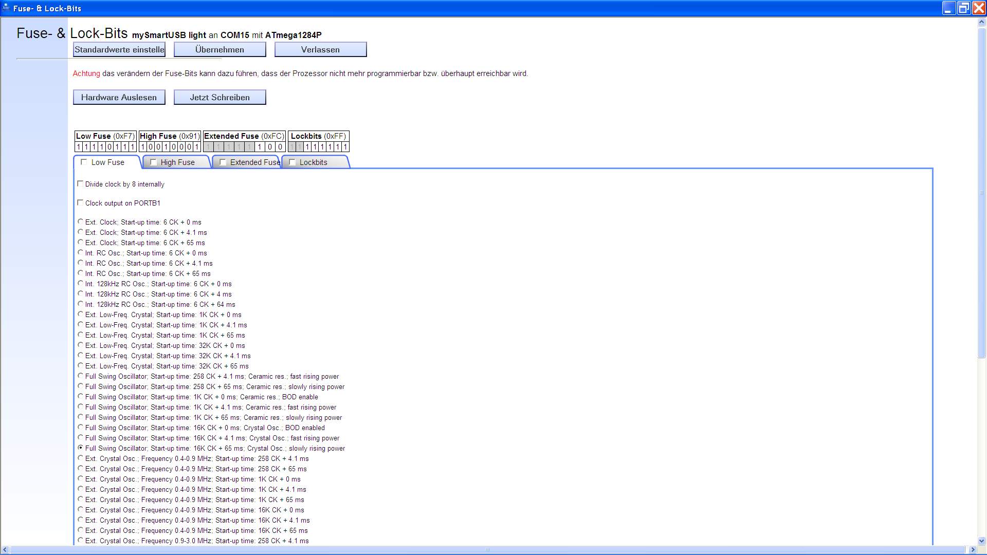
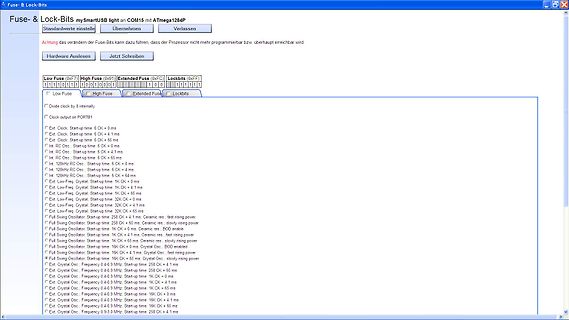
Software-Fenster zur Einstellung der Fuse- und Lock-Bits
Fuse- & Lock-Bits mySmartUSB light an ATmega1284P Standardwerte einstelle Übernehmen Verlassen Achtung das verändern der Fuse-Bits kann dazu führen, dass der Prozessor nicht mehr programmierbar bzw. überhaupt erreichbar. Low Fuse (0xF7) High
in „Floppy FDD Diskette an AVR Mikrocontroller ATmega Beispiele Assembler“ · Projekte & Code · · Screenshots
-
Datei
test2.c
/* Eine 8-kanalige PWM mit verbessertem Lösungsansatz ATmega32 @ 8 MHz */ // Defines an den Controller und die Anwendung anpassen #define F_CPU 16000000L // Systemtakt in Hz #define F_PWM 100 // PWM-Frequenz in Hz #define PWM_STEPS 256 // PWM-Schritte pro Zyklus
in „Moodlight Sourcecode hilfe“ · Mikrocontroller und Digitale Elektronik ·
-
Datei
m8535def.inc
L Y ;* ;* Number :AVR000 ;* File Name :"m8535def.inc" ;* Title :Register/Bit Definitions for the ATmega8535 ;* Date : April 16th, 2002 ;* Version :1.00 ;* Support telephone :+47 72 88 43 88 (ATMEL Norway) ;* Support fax :+47 72 88 43 99 (ATMEL Norway) ;* Support E-mail :support@atmel.no ;* Target MCU :ATmega8535 ;* ;* DESCRIPTION ;* When including this file in the assembly program file, all I/O register ;* names and I/O register bit names appearing in the data book can be used. ;* In addition, the six
in „include für AT Mega 8538“ · Mikrocontroller und Digitale Elektronik ·
-
Datei
m8535def.txt
L Y ;* ;* Number :AVR000 ;* File Name :"m8535def.inc" ;* Title :Register/Bit Definitions for the ATmega8535 ;* Date : April 16th, 2002 ;* Version :1.00 ;* Support telephone :+47 72 88 43 88 (ATMEL Norway) ;* Support fax :+47 72 88 43 99 (ATMEL Norway) ;* Support E-mail :support@atmel.no ;* Target MCU :ATmega8535 ;* ;* DESCRIPTION ;* When including this file in the assembly program file, all I/O register ;* names and I/O register bit names appearing in the data book can be used. ;* In addition, the six
in „Servomotor ansteuern, kein Interrupt!!!“ · Mikrocontroller und Digitale Elektronik ·
-
Datei
main.c
**************** // // File........: main.c // // Author(s)...: ATMEL Norway // // Target(s)...: ATmega169 // // Compiler....: IAR EWAAVR 2.28a // // Description.: AVR Butterfly main module // // Revisions...: 1.0 // // YYYYMMDD - VER. - COMMENT - SIGN. // // 20030116 - 1.0 - Created - KS // //******
in „Struct aus Flash lesen“ · Mikrocontroller und Digitale Elektronik ·
-
Datei
main.c
--------- Interrupt-Taster INT0: (www.electronicwings.com) + https://www.electronicwings.com/avr-atmega/atmega1632-external-hardware-interrupts origin written for ATmega16 https://elektro.turanis.de/html/prj271/index.html http://www.technoblogy.com/show?KX0 ADC: https://www.marcelpost.com/wiki/index.php
in „Attiny85 ADC Eingangswiderstand - wie hoch“ · Mikrocontroller und Digitale Elektronik ·
-
Datei
AVR8_Burn_O_Mat_Config.xml
caption="4.0V (3.7V - 4.5V)" Fuse1="0" Fuse2="0"/> </BrownOutDetection> <OscillatorOptions Type="ATmega8" /> </AVR> <AVR name="m16" caption="ATmega16"> <Fuse name="OCDEN" bit="7" fuseByte="hfuse" default="1" desc="Enable OCD (on chip debug)" mode="expert"/> <Fuse name="JTAGEN" bit="6" fuseByte="hfuse
in „Fehler beim Brennen von ATMEGA48 mit AVRDUDE“ · Mikrocontroller und Digitale Elektronik ·
-
Datei
V1.5_Master_6.12..txt
fünf Positionen (oben-unten;vorn-Mitte-hinten) mit Low und High-Byte ; Schaltung : SPI: MOSI, SCK ATMega8 zu ATTinys, ISP und LCD-shielt lt. Datenblatt B3,B4,B5 ; ATMega8 - ATTiny2313 ; C1 - B0 ; C2 - B0 ; C3 - B1 ; ATMega8 - LCD-shield ; C0 - A0 ADC für Joystick ; D2 - RST Taster zur Umschaltung auf
in „SPI Kopplung von ATmega8 und ATtiny 2313“ · Projekte & Code ·
-
PDF
ht16k33a_4digit_7seg.pdf
keinen erhält, kann sich aus einem Arduino / ATmega mit USB2UART-Bridge und einem CH32V003 Chip einen Programmer bauen (eine Anleitung hierfür ist für die Zukunft geplant) das Makefile wurde dahingehend geändert, dass ein Aufruf von make nicht mehr
-
Datei
3310LCD.c
NOKIA 3310 Display ***** //******************************************************** //Controller: ATmega32 (Clock: 1 Mhz-internal) //Compiler: ImageCraft ICCAVR //Author: CC Dharmani, Chennai (India) //Date: Sep 2008 //******************************************************** #include <avr/io.h> #include
in „Ladegerät für NiMH Akku mit 3310 display“ · Mikrocontroller und Digitale Elektronik ·
-
PDF
ECAD_LBB01v00_LBB02v00.pdf
FUSE-RESC3216X100N Polyfuse I-hold=0,250A; I-trip=0,50A; 16V, order code: 1206L025 Fuse Littlefuse 1206L 1 IC1 ATMEGA328P- QFP80P900X900X120-32N 8-Bit Microcontroller With 32kB In-System Programmable Flash, order code: ATmega328P-PU Microcontroller Atmel AU 1 IC2 TLC5947RHB QFN50P500X500X90-33AN 24-Channel, 12-Bit
in „LED Blinky Ball Monochrom“ · Mikrocontroller und Digitale Elektronik ·
-
Datei
tm16xx.c
Tasteninterface. Geeignet fuer: TM1651, TM1637 MCU : alle AVR ( getestet ATtiny85, ATtiny2313, ATtiny44, ATmega8, ATmega328p ) F_CPU : 8 MHz intern Pinbelegung Controller TM16xx --------------------------- PB1 CLK PB0 DIO CLK und DIO sind mit jeweils 2,2 kOhm Pop-Up Wider- staenden nach +5V zu versehen 10.01.2019
in „Siebensegment und Tasten ansteuern mit TM1651 \ TM1637“ · Projekte & Code ·
-
Datei
Bruno_Timer1_Pulsformen.ino
/* IDE 1.8.19 auf Arduino Mega2560 getestet für Arduino Leonardo ATmega32U4 23.04.2023 https://www.mikrocontroller.net/topic/553491#7395414 */ // Auf ATmega32U4 ist PB6 Arduino Pin 10 // const uint8_t pinPulsOut {12}; // OC1B bzw. PB6 invertiert const uint8_t ANZAHLTASTER
in „Präzise Pulse aus Arduino Leonardo“ · Mikrocontroller und Digitale Elektronik ·
-
PDF
AVRMKII_EN3.pdf
NTRODUCTION 1.1 What is AVR MKII? AVR MKII is a USB in-circuit programmer for controllers: Attiny, Atmega and Xmega. It cooperate with Atmel Studio and AvrDude. This AVR programmer is LUFA powered which is open source software that emulates AVRISP-MKII functionality, programmer is supported by ATMEL STUDIO
in „OLIMEX ATEMGA8 - Debugging-Modus funktioniert nicht“ · Mikrocontroller und Digitale Elektronik ·
-
Datei
spi.h
*********/ #include <avr/io.h> #ifndef SPI_H #define SPI_H /*SPI PIN CONFIGURATIONS #ifdef __AVR_ATmega32__ #define SPI_PORT PORTB #define SPI_DDR DDRB //PINS #define SCK_POS PB7 #define MISO_POS PB6 #define MOSI_POS PB5 #define SS_POS PB4 #endif */ //#ifdef __AVR_ATmega8__ #define SPI_PORT PORTB #define
in „Problem mit ADC MCP3204 und Atmega 8515“ · Mikrocontroller und Digitale Elektronik ·
-
PDF
SCHALTUNG_TV_BAS_FBAS_ATmega1284P.pdf
TV - VIDEO - BAS - FBAS - VOLLGRAFIK - s/w - ATmega1284P +5V GND 10µ 100n 450 R1 40 39 38 37 36 35 34 33 32 30 29 28 27 26 25 24 23 22 21 0 1 2 3 4 5 6 7 E N C 7 6 5 4 3 2 1 0 7 P P P P P P P P R G V P P P P P P P P P A A ATmega1284P E L L 0 1 2 3 4
in „TV BILD AVR BAS FBAS VOLLGRAFIK 320x256 Kreise Linien Punkte ASCII Assembler Atmega1284P“ · Projekte & Code ·
-
Datei
PWM_Erl__uterung.c
*****************************************/ /* Eine 8-kanalige PWM mit verbessertem Lösungsansatz ATmega32 @ 16 MHz */ /*********************************************************************/ // Defines an den Controller und die Anwendung anpassen /******************************************************
in „Problem mit der Soft-PWM“ · Mikrocontroller und Digitale Elektronik ·
-
Datei
bsp.c
**************************************************************************************** * Atmel ATmega128 * Board Support Package * * (c) Copyright 2005, Micrium, Weston, FL * All Rights Reserved * * * File : BSP.C * By : Jean J. Labrosse *************************************************************
in „gcc-avr: two or more data types in declaration specifiers“ · Mikrocontroller und Digitale Elektronik ·
-
Datei
AVR8_Burn_O_Mat_Config.xml
caption="4.0V (3.7V - 4.5V)" Fuse1="0" Fuse2="0"/> </BrownOutDetection> <OscillatorOptions Type="ATmega8" /> </AVR> <AVR name="m16" caption="ATmega16"> <Fuse name="OCDEN" bit="7" fuseByte="hfuse" default="1" desc="Enable OCD (on chip debug)" mode="expert"/> <Fuse name="JTAGEN" bit="6" fuseByte="hfuse
-
Datei
master.c
// // Anpassungen im makefile: // ATMega8 => MCU=atmega32 im makefile einstellen // lcd-routines.c in SRC = ... Zeile anhängen // #include <stdlib.h> #include <avr/io.h> #include <avr/delay.h> #define SS PB4 #define MOSI PB5 #define MISO
in „AD9833 mit SPI an MEGA32, output passt nicht“ · Mikrocontroller und Digitale Elektronik ·
-
Datei
dreh_stepp.ino
// aber nach oben begrenzen volatile int16_t count; // Zwischenzaehler fuer PCINT2-ISR volatile int32_t stepp_count; // Gesamtzaehler int32_t zaehler, alter_zaehler; // Vergleichszaehler fuer neue Ausgabewerte // beide Phasen werden zur Auswertung verwendet ISR(PCINT2_vect) { int8_t temp, neuer_zustand
in „Schrittmotor als Drehgeber mit Dynamik, AVR“ · Projekte & Code ·
-
 Bild
Bild
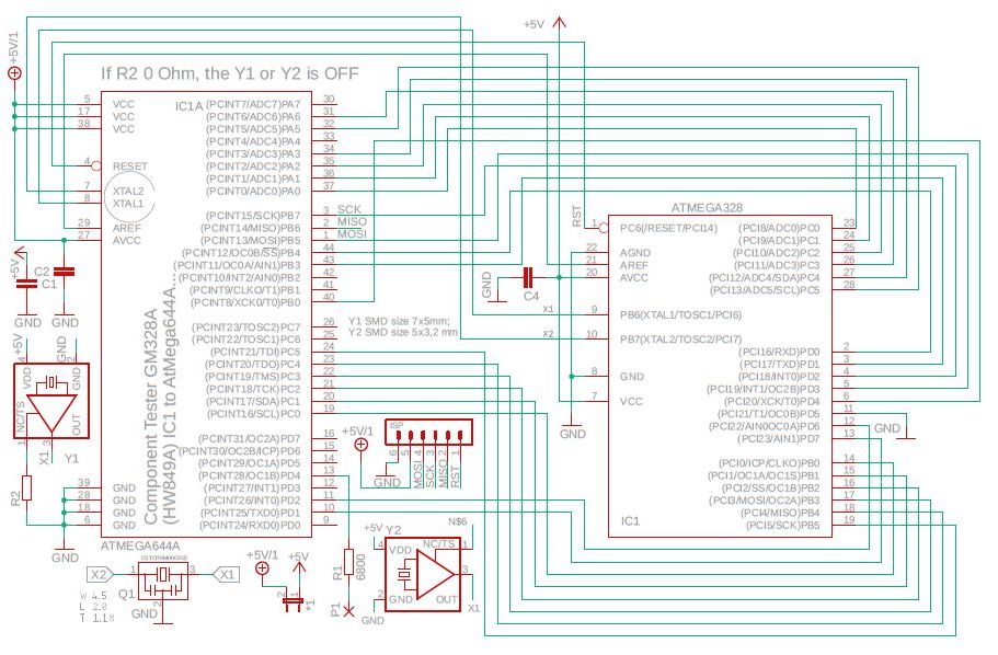
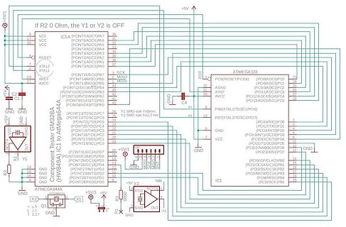
Schaltplan eines Mikrocontroller-basierten Komponenten-Testers
If R2 0 Ohm, the Y1 or Y2 is OFF +5V VCC RESET XTAL2 XTAL1 AREF AVCC GND NOCT OUT X1 R2 GND ATmega64A4 Component Tester GM328A (HW894A) IC1A (PCINT7/ADC7)PA7 (PCINT6/ADC6)PA6 (PCINT5/ADC5)PA5 (PCINT4/ADC4)PA4 (PCINT3/ADC3)PA3 (PCINT2/ADC2)PA2 (PCINT1/ADC1)PA1 (PCINT15/SCK)PB7 MISC MOSI (PCINT13/
in „Transistortester AVR“ · Projekte & Code · · Schaltpläne
-
Datei
spi.h
#ifndef SPI_H #define SPI_H #include <stdint.h> #include <avr/io.h> #if defined (__AVR_ATmega32__) #define SPI_PORT PORTB #define SPI_DDR DDRB #define SCK_PIN PB7 #define MISO_PIN PB6 #define MOSI_PIN PB5 #define SS_DDR DDRB #define SS_PORT PORTB #define SS_PIN PB4 #elif defined (__AVR_ATmega168
in „Problem durch Optimierung -Os“ · Mikrocontroller und Digitale Elektronik ·
-
Datei
test1.c
hilf = 2; for (d=0;d<=32;d++) { m_strom = m_strom + data[hilf]; hilf = hilf + 4; } hilf = 3; for ( d=0;d<=32;d++) { m_spg = m_spg + data[hilf]; hilf = hilf + 4; } //index = 0; twi_data[index]= m_gesch/32; index++; twi_data[index]=m_rich/32; index++; twi_data[index]=m_spg/32; index++; twi_data[index]=m_strom/32; index++; } void main(void) { // Declare your local variables here // Input/Output Ports initialization // Port A initialization
in „Fehler bei AD-Wandlung“ · Mikrocontroller und Digitale Elektronik ·
-
Datei
Dokument2.txt
math.h> typedef uint8_t ui8; typedef int8_t i8; typedef uint16_t ui16; typedef int16_t i16; typedef uint32_t ui32; typedef int32_t i32; typedef unsigned char ucha; typedef unsigned char byte; // *** ANFANG: Abschnitt zur Systemkonfiguration *** #if !defined (F_CPU) #define F_CPU 7372800 // uC-Takt 7,3728
in „ATmega128 USART kriegs nicht zum Laufen / bin am verzweifeln“ · Mikrocontroller und Digitale Elektronik ·
-
Datei
FG_328.ino
EEPROM //#define EEAR_SIZE uint8_t // Tiny4313 hat nur 256 Byte #define EEAR_SIZE uint16_t // fuer ATmega328 #define EE_OO_ADR 1 // 1 = eingeschaltet #define EE_P_ADR 2 // als uint32_t #define EE_W_ADR 6 // dto. #define BIT(x) (1<<x) //#define F_CPU 20000000 // 20 MHz ggf. an eff.Frequenz anpassen #define
in „PWM-Signal mit 0,1 Hz erzeugen“ · Mikrocontroller und Digitale Elektronik ·
-
Datei
test2.c
/* Eine 8-kanalige PWM mit verbessertem Lösungsansatz ATmega32 @ 8 MHz */ // Defines an den Controller und die Anwendung anpassen #define F_CPU 16000000L // Systemtakt in Hz #define F_PWM 100 // PWM-Frequenz in Hz #define PWM_STEPS 256L // PWM-Schritte pro Zyklus
in „Moodlight Sourcecode hilfe“ · Mikrocontroller und Digitale Elektronik ·
-
Datei
dmx-pwm24.h
//#define DEBUG 1 #define TARGETXX4 1 // compile for ATmega164P/324P/664(P) #define PWM10BIT 1 // use 10 bit PWM #define DMX_SIZE 24 // number of used DMX channels #define BAUD 250000L // DMX512 #define F_CPU 20000000 // system clock in Hz #define F_PWM 100L
in „C - Ersatz von switch case.“ · Mikrocontroller und Digitale Elektronik ·
-
PDF
Powermeter.pdf
should then fit into 4kB and the microcontroller can be replaced by an ATmega48, for example. • Add functions such as remote reading, demand recording or multiple tariffs. Upgrade to ATmega168, for example, if the firmware exceeds 8kB. • Add integrated LCD support simply by migrating to ATmega169. No software is ever complete and there are probably as many potential improvements Meter Firmware as there are readers of this document. The good news is the firmware is open source and can be
in „230V Leistung erfassen mit ATmega128“ · Mikrocontroller und Digitale Elektronik ·
-
PDF
volt230.pdf
should then fit into 4kB and the microcontroller can be replaced by an ATmega48, for example. • Add functions such as remote reading, demand recording or multiple tariffs. Upgrade to ATmega168, for example, if the firmware exceeds 8kB. • Add integrated LCD support simply by migrating to ATmega169. No software is ever complete and there are probably as many potential improvements Meter Firmware as there are readers of this document. The good news is the firmware is open source and can be
in „Netzteil ohne Trafo“ · Mikrocontroller und Digitale Elektronik ·
-
PDF
energymeter.pdf
should then fit into 4kB and the microcontroller can be replaced by an ATmega48, for example. • Add functions such as remote reading, demand recording or multiple tariffs. Upgrade to ATmega168, for example, if the firmware exceeds 8kB. • Add integrated LCD support simply by migrating to ATmega169. No software is ever complete and there are probably as many potential improvements Meter Firmware as there are readers of this document. The good news is the firmware is open source and can be
in „Leistungsmessung über Shunt?“ · Analoge Elektronik und Schaltungstechnik ·
-
PDF
doc2566.pdf
should then fit into 4kB and the microcontroller can be replaced by an ATmega48, for example. • Add functions such as remote reading, demand recording or multiple tariffs. Upgrade to ATmega168, for example, if the firmware exceeds 8kB. • Add integrated LCD support simply by migrating to ATmega169. No software is ever complete and there are probably as many potential improvements Meter Firmware as there are readers of this document. The good news is the firmware is open source and can be
in „Cadsoft Eagle“ · Platinen ·
-
Datei
nRF24L01_.c
react on falling edge at the nRF24L01+ interrupt output pin (which is active low). #if defined(__AVR_ATmega8__) || defined(__AVR_ATmega88A__) || defined(__AVR_ATmega168__) ISR( INT1_vect ) #else # error MCU MODEL NOT SUPPORTED #endif // defined(__AVR_ATmega8__) || defined(__AVR_ATmega88A__) || defined(__
in „nRF24L01+ Funkmodul - Auto Acknowledgement sendet keine Payload“ · Mikrocontroller und Digitale Elektronik ·
-
Datei
Bestell.txt
Bauteil Best.Nr. Stck. Preis -------------------------------------------------- 74HC73 74HC 73 1 0,22 ATmega8 ATMEGA 8-16 DIP 1 1,70 Quarz 16MHz 16,0000-HC49U-S 1 0,24 Spule 100µ SMCC 100µ 1 0,16 Taster TASTER 3305B 1 0,12 IC-Sockel GS 28P-S 1 0,36 Gehäuse SP 2090 SW 1 2,20 33p NPO-G1206 33P 2 0,10 100n X7R-G1206 100N 5 0,30 3,3n X7R-G1206 3,3N 1 0,06 10n X7R-G1206 10N 1 0,06 7 Segment SC 39-11 RT 4 2,32 7805 µA 78L05 SMD 1 0,12 160R SMD 1/4W 160 8 0,80 1k SMD 1/4W 1,0K 5 0,50 150R SMD 1/4W 150 1 0,10 1M SMD 1/4W 1,0M 1 0,10 2,2M SMD 1/4W 2,2M 1 0,10 33k SMD 1/4W 33K 1 0,10 27k SMD 1/4W 27K 1 0,10 68k
in „Multimeter“ · Projekte & Code ·
-
 Bild
Bild
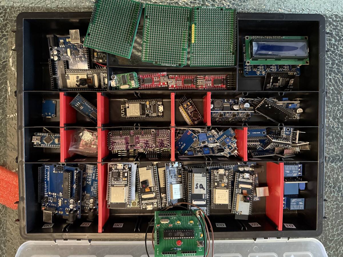
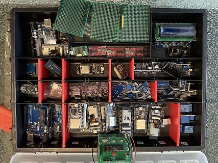
Sortiment an Mikrocontrollern und Leiterplatten in einer Kunststoffbox
Arduino, ATmega, ESP32, STM32, LCD
in „(V) elektronische Bauelemente“ · Markt · · Fotos
-
 Bild
Bild
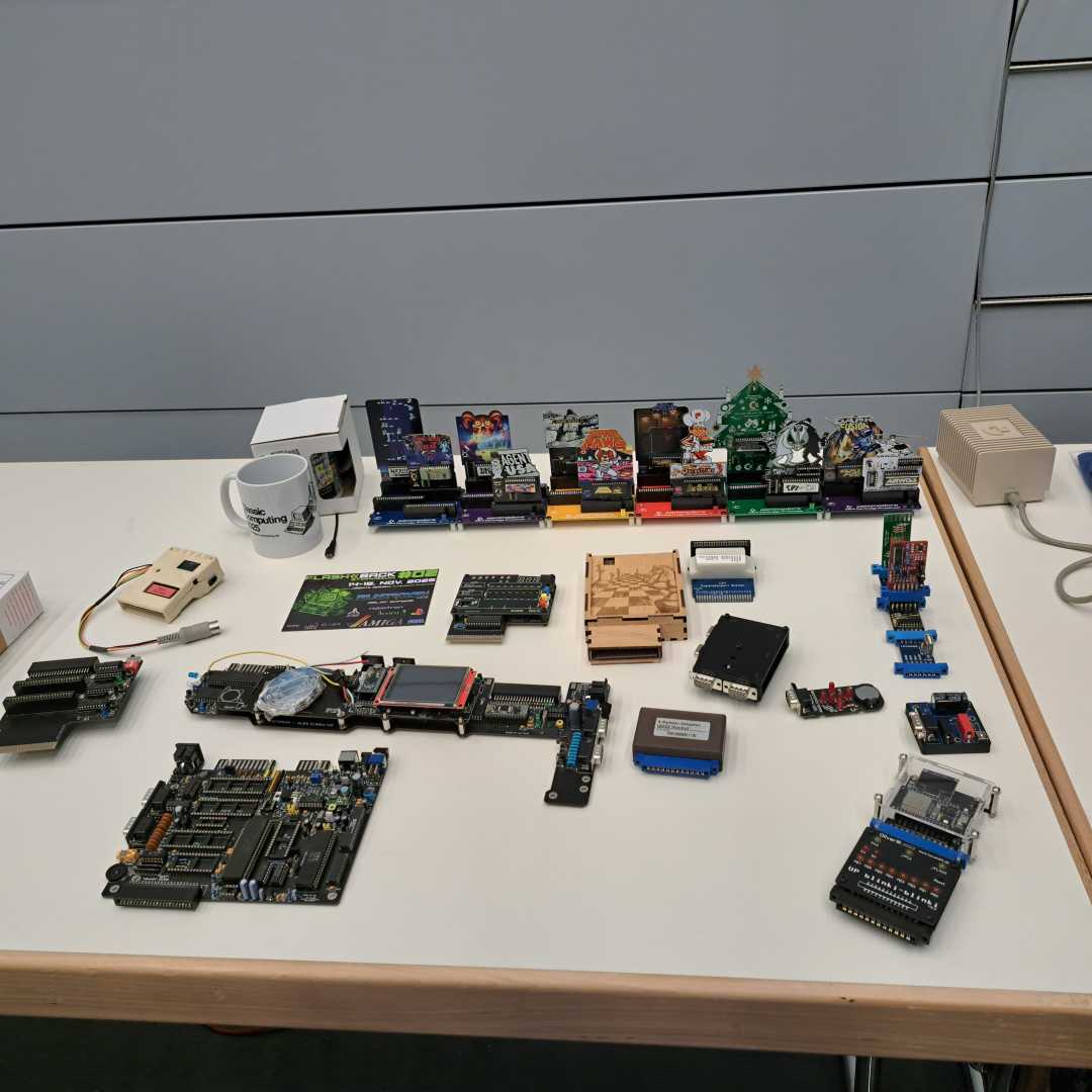
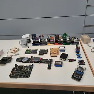
Sammlung verschiedener Mikrocontroller-Boards und Elektronikkomponenten
Arduino, Raspberry Pi, ESP32, STM32, ATmega
in „Veranstaltungstipp: Retro-Computing Treffen 2025“ · Offtopic · · Fotos
-
Datei
fixapfel.cpp
fixpointSqr (fixpoint x) { return fixpointMult (x, x); } fixpoint fixpointSqrt (fixpoint x) { uint32_t r = 0; uint32_t hi = 0; uint32_t lo = x; uint32_t c = 15 + (fixpointFractShift >> 1); uint32_t d; do { hi = (hi << 2) | (lo >> 30); lo <<= 2; r <<= 1; d = (r << 1) + 1; if (hi >= d) { hi -= d; r +=
-
Datei
HeizgV20.c
****************************************************************************** Project : Heizung ATmega32 Version : V2.0 Date : 15.09.2010 ATMEGA32 Compiler: WIN-AVR Status des Programms: 29.11.2006 Fehler im Taktgenerator (Uhr ging falsch) 15.07.2009 umgeschrieben auf Win_avr Compiler Fleury's LCD und
in „Heizungssteuerung mit ATMEGA 32“ · Mikrocontroller und Digitale Elektronik ·
-
Datei
DDS_Jesper.txt
.include "m32def.inc" ;ein ATMEGA32 steckt im Sockel .def temp1 = r21 ;Register mit dem Daten oder Befehlsbyte .def temp3 = r20 ;Hilfsregister von dem subtrahiert wird .CSEG .org 0 rjmp RESET ;********************
in „Probleme mit DDS (Jespers)“ · Mikrocontroller und Digitale Elektronik ·
-
Datei
Neigungssensor_2014_05_12.c
----------------------------------------- // Titel : Hauptprogramm Neigungssensor // Prozessor : ATmega8 mit 3,6863 MHz // Funktion : // Schaltung : D.2 Taster1, D.3 Taster2 // B.0 Rote, B.1 Gelbe, B.2 Grüne // Sprache : C // Datum : 12.05.2014 // Version : 1.0 // Autor : Stefan Hohmann //-----------
in „Festkommaarithmetik und itoa Problem“ · Mikrocontroller und Digitale Elektronik ·
-
Datei
Neigungssensor_2014_05_12.c
----------------------------------------- // Titel : Hauptprogramm Neigungssensor // Prozessor : ATmega8 mit 3,6863 MHz // Funktion : // Schaltung : D.2 Taster1, D.3 Taster2 // B.0 Rote, B.1 Gelbe, B.2 Grüne // Sprache : C // Datum : 12.05.2014 // Version : 1.0 // Autor : Stefan H. //----------------
in „Festkommaarithmetik und itoa Problem“ · Mikrocontroller und Digitale Elektronik ·
-
Datei
FloatApfel.c
return erg; } } char* floattoa (float x, char* str) { int16_t ie = 0; bool lessOne = false; float y; int32_t z; int32_t zz; char mant [11]; size_t len; uint8_t n; int16_t m; char* res = str; if (x == 0.0) { *str++ = '0'; } else { //--- Ggf. negieren, x muss im folgenden positiv sein --- if (x < 0) { *str+
-
Datei
PWM-Test.c
/* Eine 8-kanalige PWM mit intelligentem Lösungsansatz ATmega32 @ 8 MHz */ // Defines an den Controller und die Anwendung anpassen #define F_CPU 16000000L // Systemtakt in Hz #define F_PWM 100L // PWM-Frequenz in Hz #define PWM_PRESCALER 8 // Vorteiler für den
in „Problem mit der Soft-PWM“ · Mikrocontroller und Digitale Elektronik ·
-
PDF
AVR_Stamp_sheet_V1_1.pdf
20 A1 (A9)PC1 36 A9 PG3 21 21 A0 35 A8 PG2 22 22 (A8)PC0 PG1 23 23 ZRESET BUSREQ PG0 BUSREQ (T0)PD7 32 24 24 (T1)PD6 31 BUSACK SDA 25 25 BUSACK 30 ZRESET SCL 26 26 RXD0 (XCK1)PD5 29 MREQ 27 27 TXD0 (ICP1)PD4 28 RD CLKO 28 28 RD (TXD1/INT3)PD3 WR WR (RXD1/INT2)PD2 27 29 29 (SDA/INT1)PD1 26 SDA 30 30 M1 25 SCL 31 31 MREQ (SCL/INT0)PD0 32 32 IORQ 9 CLKO C (CLKO/ICP3/INT7)PE7 C (T3/INT6)PE6 8 INT6 PINHD-1X32 PINHD-1X32 (OC3C/INT5)PE5 7 INT5 6 PE4 (OC3B/INT4)PE4 5 PE3 (OC3A/AIN1)PE3 4 PE2 (XCK0/AIN0)PE2 (TXD0/PDO)PE1 3 TXD0 (RXD0/PCIN8/
in „Z180-Stamp Modul“ · Mikrocontroller und Digitale Elektronik ·
-
Datei
spi.c
#include "spi.h" uint8_t init_spi() { #if defined (__AVR_ATmega32__) SPI_DDR |= (1<<SCK_PIN) | (1<<MOSI_PIN); SS_DDR |= (1<<SS_PIN); SPI_PORT &= ~((1<<SCK_PIN) | (1<<MOSI_PIN) | (1<<MISO_PIN)); SS_PORT |= (1<<SS_PIN); SPCR = (1<<SPE) | (1 << MSTR); SPSR = (1<<SPI2X); #elif defined (__AVR_ATmega168__) SS_DDR |= (1<<SS_PIN); SS_PORT |= (1<<SS_PIN); SPI_DDR |= (1<<MOSI_PIN)|(1<<SCK_PIN); SPCR = (1<<SPE)|(1<<MSTR)|(1<<SPR0); #endif return 0; } void set_cs(uint8_t state) { if(state) { SS_PORT
in „Problem durch Optimierung -Os“ · Mikrocontroller und Digitale Elektronik ·
-
Datei
reichelt_st_te.txt
Wannenstecker für AKL 249, 2-pol, RM5,08 0,17 1 AKL 249-02 Anschlussklemmensystem 2-pol, RM5,08 0,37 1 ATMEGA 32-16 DIP ATMega AVR-RISC-Controller, DIL-40 6,20 1 MAX 232 CPE RS232-Driver, DIL-16 0,40 1 LED 5MM ST GN LED, 5mm, Standard, grün 0,08 1 LED 5MM ST RT LED, 5mm, Standard, rot 0,08 1 UA 7805 Festspannungsregler
in „Stückliste für Webserver“ · Mikrocontroller und Digitale Elektronik ·
-
Datei
Quellcode.txt
++++++++++ BASCOM Quellcode +++++++++++++++++++++++ $regfile = "M32def.dat" $crystal = 16000000 $lib "i2c_twi.lbx" Config Scl = Portc.0 Config Sda = Portc.1 I2cinit Config Twi = 100000 I2cstart I2cwbyte &H40 I2cwbyte &H0F I2cstop Do Loop End ++++++++++ Assembler Quellcode +++++++++++++++++++ .DEVICE ATmega32 .INCLUDE "m32def.inc" ; *** Konstanten *** .equ SCL = PC0 .equ SDA = PC1 .equ dev_read = 0b01000001 .equ dev_write = 0b01000000 .equ data = 0b00001111 .equ bit_anz = 0x08 ; *** Variablen *** .def
in „I2C-Bus funktioniert mit BASCOM aber nicht mit Assembler“ · Mikrocontroller und Digitale Elektronik ·