6 06 ⎯ ⎯ 3E4 H 000FFFE4 H ⎯ System reserved 7 07 ⎯ ⎯ 3E0 H 000FFFE0 H ⎯ System reserved 8 08 ⎯ ⎯ 3DC H 000FFFDC H ⎯ System reserved 9 09 ⎯ ⎯ 3D8 H 000FFFD8 H ⎯ System reserved 10 0A ⎯ ⎯ 3D4 H 000FFFD4 H ⎯ System
D U T T T T T S L D / / / / / D / / / / / D S 3 2 1 D 0 9 8 7 6 5 4/ D 3 S 2 D 1 0 9 8 7 6 5 4/ O Y _ G O R A V V O P A O V O A O V O E E E E E V C D 6 6 6 6 5 D 5 5 5 5 5 D V 5 5 5 D 5 4 4 4 4 4 4 D 4 V 4 D 4 4 3 3 3 3 3 3 M D S X C V A A O C A A C A A T T T T T C V
NO. VERSION PAGE TECHNOLOGIES CORPORATION E T 0 7 0 0 G 0 D M 6 12 0-1 DOC . FIRST ISSUE FEB.17, 2009 R E C O R D S REVISED R E V I S I O N D A T E PAGE S U M M A R Y NO. FEB.18, 2009 3 4. ELECTRPARAMETERACTERISSYMBOL CONDITION MIN. TYP. MAX.
. . . . .-. 2 3 . . . . . . . . . 4 . 4 .1 3 S electio n o f S w eep M o d e/T rig g er M o d e . . . . . . . . . . . . . . . . . . . . . 4 - 2 4 . . . 4 .1 4 D isp lay D etectio n M o d e . . . . . . . . . . . . 4 - 2 5 (1) SAM PLE DETection
. BLOCK DIAGRAM Host LCD module (Product) D0+ 100 H-driver D0- D1+ 100 S V D1- L D2+ f 1,920 lines e 100 i c D2- r D3+ i w LCD panel 100 e s r r i n v 0 H: 640 × 3 (R, G, B) D3- C d 4 V: 480 CK+ V 100 CK- DPS FRC Power supply for gradation k k 5 4 GND Note1 Note2 DC/DC VCC converter Fuse FG LCD panel
A4915 Demo Board Schematic/Layout D C B A SCHEMATIC C 2 V v r T C N C l m o N D 7 6 5 4 3 2 1 0 O g v s 3 4 3 2 1 e e a J o M o M e 1P i 1 V a v D d t 1 t o g 1 H t n o A R R R p ce h 1 1 1 n ther D C 9 8 1 6 . e a D H 7 C p n B 2 l V L k k k k y , D 1 1 u F k R 4 R 5 . 4 k U B N 2 N G
transport transmission. 3.More information reference the below: http://www.usr.cn/Search/getList/keyword/%E8%99%9A%E6%8B%9F%E4%B8%B2%E5%8F%A3/ 4.3. Serial Port Function Jinan USR IOT Technology Limited 37 / 107 inquiry@usriot.com USR-K6 User Manual www.usriot.com 4.3.1. Basic Parameters Diagram 4.3.1-1Basic
THAT POINT WHERE THE PEAK ) PULSE WAVEFORM CURRENT DECAYS TO 50% OF k SHOWN IN FIGURE 2 PP. ( 10 100 E ) PEAK VALUE PPI O ( P E A L IPP P V HALF VALUE - 2 ,P 50 P 1 t P 0.1 0 0.1 ms 1 ms 10 ms 100 ms 1 ms 10 ms 0 1 2 3 4 5 P , PULSE WIDTH t, TIME (ms) Figure 1. Pulse Rating Curve Figure 2. Pulse Waveform
C3 Y 02CC30 SKRAAKE010 SKRAAKE010 SKRAAKE010 D 2 D 2 1n 7 7 01 1 2 1 2 1 2 L 11 L 11 W1 2 01 2 01 E I1 E I1 0 0 0 0 GND GND GND OR 2 OR 2 S Push-Buttons POOEDS0LES1 E LED0 I2 I2 POBUTTON1 POBUTTON2 POBUTTON3 L LED1 2 Yellow LEDs C C POHEEDEDJ40PJN7 6 4 2 0 J4 1 3 5 7 I I I I I I I I P P P P P P P P
number of consecutive partial page programming operation within the same page without an intervening erase operation must not exceed 4 times for a single page. The addressing should be done in sequential order in a block. [/code] Hier darf das teilweise Beschreiben einer Page nur 4x erfolgen. Dann sollte die Page wieder gelöscht werden.
ICM-20948 4.2 TYPICAL OPERATING CIRCUIT VDDIO nCS SCL SCLK K K SDA I L SDI I L S S A S S A / L _ V V / L _ V V D C C U E E D C C U E E S S n A R R S S n A R R 4 3 2 1 0 9 4 3 2 1 0 9 2 2 2 2 2 1 2 2 2 2 2 1 NC 1
vs Temperature - "X" Figure 2. Iq V IN (Active) vs Temperature - "Y" IN 0.615 0.610 z M 0.605 Y C E 0.600 Q R 0.595 F O 0.590 A I S 0.585 O 0.580 0.575 -50 -25 0 25 50 75 100 125 150 TEMPERATURE ( C) o Figure 3. Oscillator Frequency vs Temperature - "X" Figure 4. Oscillator Frequency vs Temperature - "Y" 93.4 96.55 96.5 93.3 96.45 ) 93.2 E ( L 96.4 L Y Y 93.1 C 96.35 Y T 96.3 U U D 93.0 D 96.25 A A M 92.9 M 96.2 96.15 92.8 96.1 92.7 96.05 -40 -25 0 25 50 75 100 125 -50 -25 0 25 50 75 100 125 150 o TEMPERATURE
https://www.spiegel.de/wirtschaft/unternehmen/gazprom-fuellt-deutsche-gasspeicher-nicht-auf-a-a76e5e8a-ba67-4d86-8846-6af453c5df5e Sieht so ein zuverlässiger Lieferant aus?
o o r 0 2 2 0 _ c _ c 1 C C / U K U S C r r 5 E U A U A o o , E E 5 K 4 ) I D : K T N r O B O A U m M W R L L f P S ( C P n y 0 r 0 P S r a e o e 0 o 4 F R T i a c a 2 - E p o e B E T W o v s i T P L 6 l - n 4 l o : n O B i U P p E O I T ) W N r D U o R n E t I W g W A C k D D 2 - a E 4 B 3 E D 4 B ( i a : W b o t B P C M t c P 1 o s r i i c l I M b M b F n N R 6 R 6 C o U F 1 F 1 O D U L M i M i 1 E A b A b 3 R 1 R 4 4 t S S E M : e M i B i A b P W R 1
transistors must be designedtowithstand;start-upwithasupplyvoltage The start-up circuit operates in the same way as in Figure 4. Steady state waveforms of the voltage source ballast Ilamp (0.2A / Div) IC (0.2A / Div) I (0.1A / Div) V (100V / Div) 4/10 APPLICATION NOTE 20V above the nominal value of 120V RMS
Address 0) can be written from “1” to “0”. The execution times and the required clock pulses are the same as described under UPDATE MAIN MEMORY. Command: UPDATE SECURITY MEMORY Control Address Data B7 B6 B5 B4 B3 B2 B1 B0 A7…A0 D7…D0 Binary 0 0 1 1 1 0 0 1 Address Input data Hexadecimal 39H 00H…03 H Input
of main features of the module Parameter Description Power supply VBAT supply voltage range: 3.3V~4.2V Typical supply voltage: 3.8V Transmit power Class 4 (33dBm±2dB) for GSM850 Class 4 (33dBm±2dB) for GSM900 Class 1 (30dBm±2dB) for DCS1800 Class 1 (30dBm±2dB) for PCS1900 Class E2 (27dBm
die Zellenspannung bei Entladeschluß bei 0,9V/Zelle. Deine Gerät läuft also wohl mit 6x 0,9V = 5,4V statt 9V nicht mehr. Gruß aus Berlin Michael
questions/571226/how-many-amperes-can-an-alkaline-aa-battery-supply Energizer datasheet shows the same trend, at 500mA the capacity is reduced to 1500mAh, where it does 3000mAh at 25mA. https://data.energizer.com/pdfs/e91.pdf
Vanye R. schrieb im Beitrag #7449077: > > 4. Du findest eine kleine Spezialbude die auf die Reparatur > spezialisiert > ist und die das fuer 20000 repariert und in Zukunft alle 1-2Jahre > bei dir zu Gast ist. 4a. Man besorgt sich
E34 L. schrieb im Beitrag #7449021: > Ein RasPi4 mit SSD wäre sicher genauso gut, aber damals gabs das halt > noch nicht. Und in der Industrie ist man gerne mal etwas "hinterher" mit > der Technik (
dieselben Zufallswerte in das System einzuspeisen. Damit ließe sich die Kryptografie des System m.E.n angreifen (z.B. schwache Schlüssel oder gleiche Nonces generieren).
(sat) C 10 100 ) ) 75°C 25°C p 9 f = 10 kHz A E ( C 8 E = 0 A T 10 TA= −25°C N 7 TA= 25°C E I R C 6 R P C 1 A 5 R C O U 4 T P E 0.1 U 3 L O O b 2 ,0.01 C 1 I VO= 5 V 0 0.001 0 10 20 30 40 50 0 1 2 3 4 5 6 7 8 9 10 V , REVERSE VOLTAGE (V) V , INPUT
Ich bin dabei die Konfiguration für die Clock Chain eines AtSamC21E15A einzustellen. Dabei bin ich darüber gestolpert, dass laut Datenblatt für das FDPLL96M Modul als Quelle der Generic Clock Controller möglich ist. Der Generic Clock Controller hat ja 8 Generatoren
more details (b14116f) • esp_chip_info() returns the chip version in the format = 100 * major eFuse version + minor eFuse version. (c546de8) • Wi-Fi: Modified maximum SoftAP connection number and ESPNOW encrypted connection number. (d89a512) • Wi-Fi: Changed ESP-NOW receive callback
mode. (f27a95c) • Wi-Fi: Added support for SAE-PK (Public Key) authentication for station. (e44c7fb) • Wi-Fi: Added support of WPA3 Personal (SAE) in SoftAP. (146a5c4) • Wi-Fi: Added Wi-Fi Aware (NAN) support(currently only ESP32/ESP32S2 support)(d5f53fb) • Wi-Fi: Added support
ABSOLUTE TUMIDITY MUST BE LOWER THAN THE HUMIDITY OF 90%RayAT 60 te96HRS MAX). sl iu Di it ng td rgi no m e Do E 02101300-01-02 E M E R G I ND I S P L A YDEL NO. VERSIOPAGE TECHNOLOGIES CORPORATETEMB043013XDHAL 2 4 4. ELECTRICAL CHARACTERISTICS 4.1 EMBEDDED SYSTEM ELECTRICAL CHARACTERISTTa 25 C POWER SUPPLY
E. schrieb im Beitrag #7443834: > muss ich beim Kauf schon darauf achten, dass man einen Batteriespeicher > anschließen kann? Ja. Viktor E. schrieb im Beitrag #7443834: > Beispiel für die Batterie
teuer pro kWh, nur verwendbar wo wenig Zyklen und Kosten egal sind, eben beim Camping. Nur LiFePo4 mit 3500, besser 7000 Zyklen sind pro kWh günstig genug, und unter 48V ist die Leistung gering. Viktor E. schrieb im Beitrag #7443834: > Meine Idee ist aber keine reine Insellösung, sondern ein
“Vaporware”- bzw. Vorankündigungsphase steht die vierte Generation des Arduino-Evergreens Arduino R4 in gleich zwei Varianten im Arduino Store zur Verfügung. Was Arduino Uno R4 Minima und Uno R4 WiFi von den Vorgängern unterscheidet, klärt dieser Artikel. 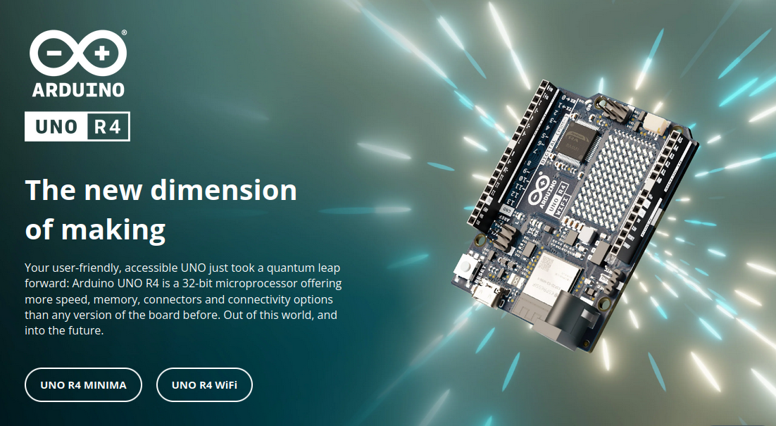 Bildquelle
MHz zur Verfügung, der Flashspeicher ist nun 256KB groß. Das RAM ist 32KB groß. ### Arduino Uno R4 Minima – preiswert, mit ISCP-Connector Beim unter https://store.arduino.cc/products/uno-r4-minima um 18 EUR erhältlichen Arduino Uno R4 Minima setzt Arduino im Allgemeinen auf bekannte Kost: neu ist
1 3 7 % 3 0 1 2 R 4 9 . R 1 2 R K N 3 E 1 1 3 R F 3 3 3 3 2 1 1 3 1 2 2 2 2 2 2 D G 7 2 . C S I C T C D C N D D D D D 1 C A C 0 1 O S F O M M N E E E E E E N S 0 R V S S E L L L L L V 3 A D 4 D T S 8 2 1 V D V 3 2 0 3 8
flicker corner frequency of the oscillator device, typical values for transistors are AF = 2, KF = 1E-5 to 1E-9. These are the equivalent SPICE parameter values which determine the corner frequency. Microwave transistors typically have a corner frequency between 1 and 5KHz with a tendency that the corner
- Support CMPCCXADD instructions. crc32 - Enable SSE 4.2 CRC32 instruction (used when SSE4.2 is supported but function is GPR only). cx8 - Support CMPXCHG8B instructions. enqcmd - Has ENQCMD
Operationsverstärker. Ich versuche seit Tagen weiter zu kommen, aber es klappt nicht. Ich hab drei E-Techniker gefragt und alle können mir warum auch immer nicht weiterhelfen... 2 PT100 Sensoren sind an einen MCP6004T OpAmp angeschlossen, welcher wiederum an den integrierten 12bit ADC von einem SAME70
allen möglichen Varianten verkauft: https://yiweitech.aliexpress.com/store/group/FFC-Cable-1-0mm-Same-Ends/900038_509418576.html
Stromleitungen voll dabei sein. 1 Meter ist wie oben erwähnt zu lang, die von Harald.K gefundene Anzeige auf eBay ist ausreichend und kurzfristig verfügbar. Danke für die Teilnahme
1 R 0 D U 7 1 C T8 – U1 6 R6 F 2 2 R1 3 * 2 F 2 7 U 2 R + OPA603 1K 6 R 0 C 1 R T5 T12 IRF640 2K2 4 5 1 F F R29 INPUT 0 C0 6E 8 2K2 7 3 OUTPUT J2 C1 1 4 C2 RBD139 BC337 . R J1 µ 3 1 0 K 3 . C E 2 4.7 µF 1 R–15V 0 BC327 2 3 C4 0 P R30 0 R K * 3 F 3 2 2K2 0 R 22pF GND 6 1 0 1 4T13 IRF9640 1 5 R 1 C 0 K 8 R5 4 3 2 R 0 2 F D 4 T9 GND GND 22K 0 R U 0 D p 0 0 2 GND 1 4 0 C 1 R 0 4 F T4 U 1 5 R 0 9K IRF9640 1 C0 R 1 MJE340 GND 5 T3 p 1 0 2T10 0 C 1 R 1 MJE340 IRF9640 F 0 1 0 1 K 1 n 1 1 C 1 R 1 R 1 C E 6 F 6 p
234 mm Parasitic elements fastened to a non-metallic or separated from boom Folded dipole mounted same as directors and reflector Director/reflector diam =2 mm Radiator diam =2 mm REFLECTOR 113.8 mm long at boom position = 150 mm (IT = 47.0 mm) RADIATOR Single dipole 109.4 mm tip to tip, spaced
234 mm Parasitic elements fastened to a non-metallic or separated from boom Folded dipole mounted same as directors and reflector Director/reflector diam =2.85 mm Radiator diam =2.85 mm REFLECTOR 113.4 mm long at boom position = 20 mm (IT = 46.5 mm) RADIATOR Single dipole 108.7 mm tip to tip
mounting surface flatness, i.e., h/TlR, if less than 4 ÉÉÉÉ ÉÉÉÉÉÉÉÉÉ mils per inch, normal for extruded aluminum, is satisfactory ÉÉÉÉ ÉÉÉÉÉÉÉÉÉ in most cases. &▯▯▯&▯"▯▯$▯▯▯▯ ▯▯*▯▯▯ !#)"(▯"▯ ▯&▯▯ Surface Finish Figure 2. Surface
limit values given by Eq. 10 have virtually duty factor as a parameter. been reached at t =p10 s.-6 1E+01 Zth j-mb / (K/W) BUK553-100A = 1E+00 0.5 0.2 0.1 1E-01 0.05 0.02 1E-02 D tp = t 0 T t 1E-03 T 1E-07 1E-05 1E-03 1E-01 1E+01 t / s Fig. 9 Example of the presentation of the transient thermal impedance
mode. The serial interfaces are mapped onto the same pads. To select/exploit the I C interface, CS line must be tied high (i.e connected to Vdd_IO). Table 2. Serial interface pin description Pin Name Pin Description CS SPI chip select (CS) I C/SPI selector
the I C and SPI serial interfaces. The latter may be SW configured to operate either in 3-wire or 4-wire interface mode. The serial interfaces are mapped onto the same pads. To select/exploit the I C interface, CS line must be tied high (i.e connected to Vdd_IO). Table 8. Serial interface pin description
I L O 1 1 5 R27 T B S 3 M e e u 14 0 2 T T 1 L 11 6 6 0K 5 6 7 i a o DL 1 k D L R5 0 3 1 00 17 0 V 60 T D D 2 R 2 0 4- 17 R4 0 3 5 + - B N 1K 2 6 2 T BT 2 R4 1u 0 n 0 C R1 4 3 2 22 1. 1 0 1 8 R 0 4- 2 6 1 3 0K C0 C 1 7 I 0 2 T
waren noch Zeiten ... 🥰 Ralph S. schrieb im Beitrag #7423929: > Na ja. Die FPU eines Cortex M4F ist schon eine Neuerung (für mich). > Berechne mal ein Apfelmännchen auf einem STM32F103 und dann auf einem > STM32F4xx. Die FPU im M4 ist schon sehr praktisch, insbesondere für digitale Signalverarbeitung
V. Veit D. schrieb im Beitrag #7424154: > Warum ist bei 32 Bit STM dominant und nicht die AVR SAM? Beide nutzen > ARM Kerne. Was macht STM so beliebt? Was machen die besser bzw. anders? Anfangs hatte ich ein AT91SAM7S-EK Board mit SAM-ICE von Segger. Der µC konnte mit diversen Renesas Controllern
dabei so aus: Der Wandler (SMD:"00=BOB") arbeitet mit 500kHz und verwendet eine Induktivität von 4.7µH. Nach einer Formel aus einem Datenblatt beträgt der Ripple-Strom 1200mA (=(12-5)*5/12/500e3/4.7e-6). Verbaut wurden zwei 220uF Elkos mit 6.3mm Durchmesser. Es gibt auch Elkos in dieser Baugröße die
Sam W. schrieb im Beitrag #7423127: > Polymer-Feststoffkondensatoren nöö, das sind stinknormale Al-Elkos, sogar minderwertige 30000h könnte man mit excellenten Teilen erreichen, z.B. NCC LXZ oder
