-
 Bild
Bild
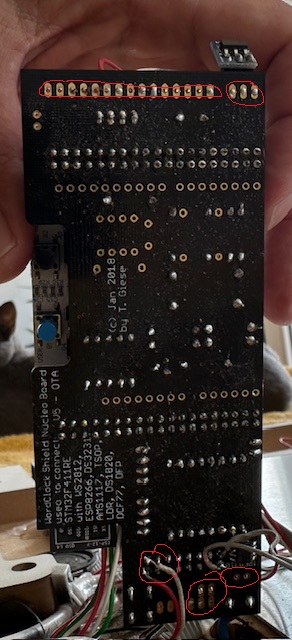
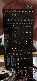
Rückseite einer Hardlock Shield Nucleo Board Leiterplatte
(c) Jan 2018 by T. Giese Hardlock Shield Nucleo Board STM32F411RE with ESP8266, DS3231, AMS1117, TSL2561, LDR, DS18B20, DFPlayer Mini, DCF77
in „WordClock mit WS2812“ · Projekte & Code · · Platinenfotos
-
PDF
Schaltung_Datenlogger_Bluetooth.pdf
Magnetschalter TPL5110 Delay RTC-Modul VSYS 100 nF Li3,1 V MADC Done BLE 1Batteriespannung Ergänzung DS3231 820 K SEEEDXIAO EPS32-C3 D6 D7 SDA SHT31D SCL Sensor
in „Stromsparende Schaltung Klimalogger auf Basis Rasp Pi Pico“ · Mikrocontroller und Digitale Elektronik ·
-
Datei
AquaDosierung_V1_2.ino
pause_hour = 0; char pause_min = 0; char pause_day = 0; char pause_month = 0; /*-----[ Zeitmodul DS3231 einlesen und aktivieren )-----*/ void setDS3231time(int second, int minute, int hour, int ndofweek, int dday, int dmonth, int dyear) { Wire.beginTransmission(ADDR_RTCDS3231); Wire.write(0); Wire.write
in „Arduino LCD Backlight auto off“ · Mikrocontroller und Digitale Elektronik ·
-
 Bild
Bild
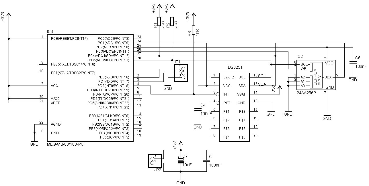
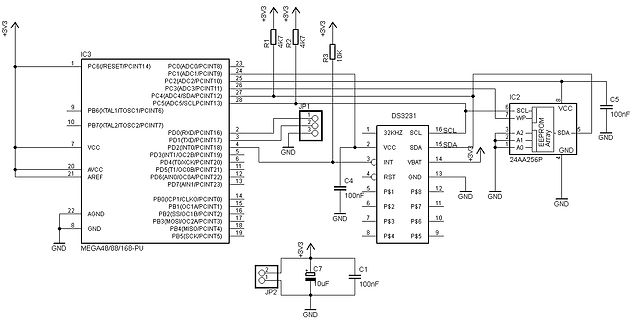
Schaltplan mit ATmega48 und EEPROM
OC1B/PCINT28) 16 PB3(MOSI/OC2A/PCINT29) 17 PB4(MISO/PCINT30) 18 PB5(SCK/PCINT31) 19 IC2 24AA256P DS3231 JP1 JP2 R1 R2 R3 C1 C4 C5 C7 GND VCC +3V3 100nF 10uF 4K7 10K
in „Temperaturdatenlogger OK? (Mega328,DS3231,I2C-EEPROM)“ · Mikrocontroller und Digitale Elektronik · · Schaltpläne
-
 Bild
Bild
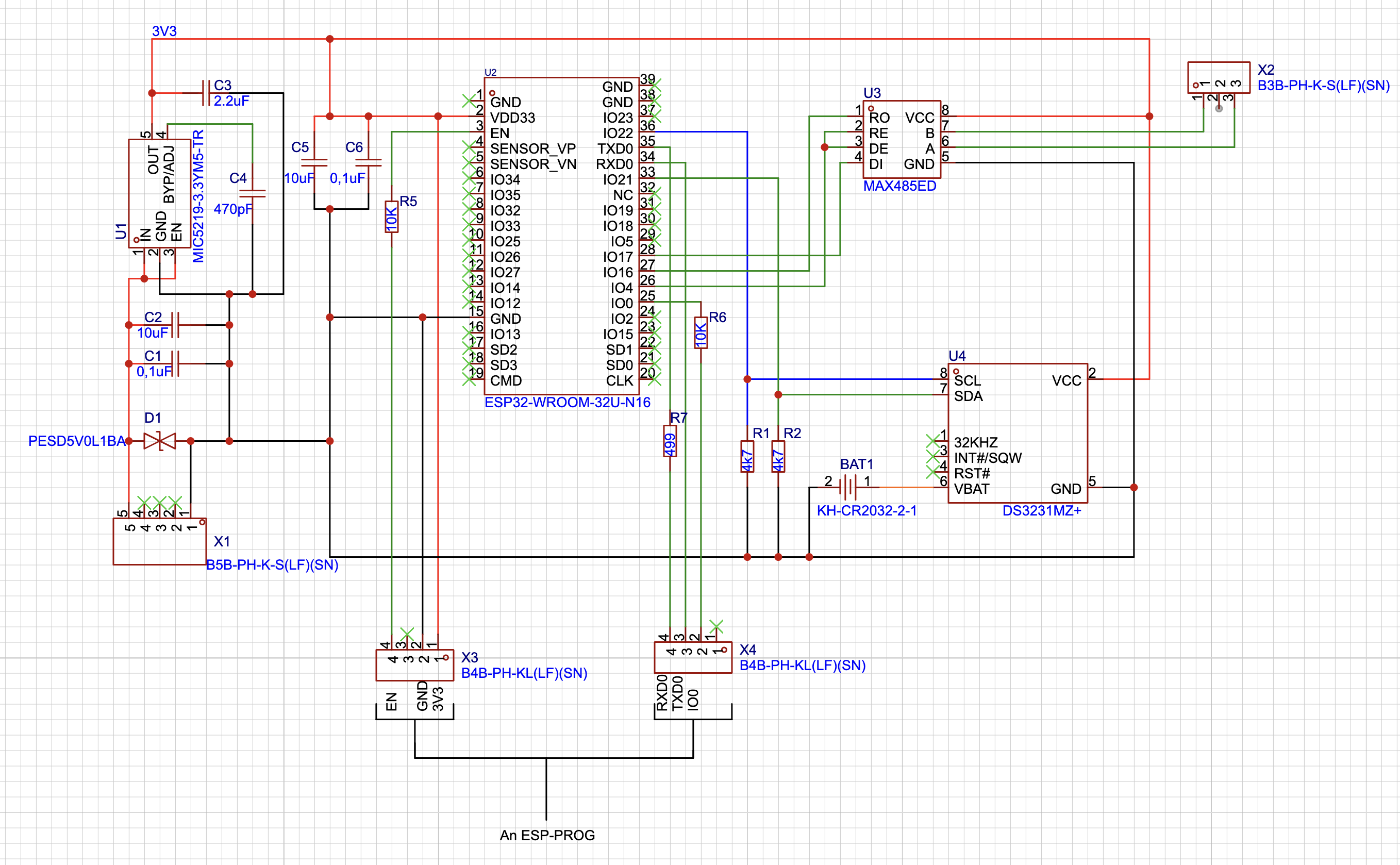
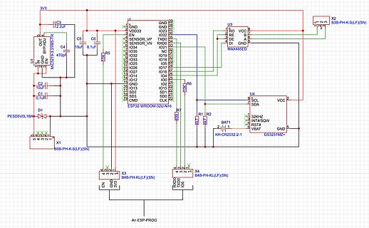
Schaltplan eines ESP32-Entwicklungsboards
, R5 10K, R6 10K, R7 10K, U3 MAX485ED, RO, RE, DE, DI, A, B, GND, VCC, X2 B3B-PH-K-S(LF)(SN), U4 DS3231MZ+, SCL, SDA, VCC, 32KHz, INT#/SQW, RST#, VBAT, BAT1, KH-CR2032-2-1, R1, R2, X1 B5B-PH-K-S(LF)(SN), D1 PESD5V0L1BA, C1 0,1uF, C2 10uF, C4 470pF, C5, C6, X3 B4B-PH-KL(LF)(SN), X4 B4B-PH-KL(LF)(SN),
in „Probleme beim flashen des ESP32 mit ESP-PROG“ · Mikrocontroller und Digitale Elektronik · · Schaltpläne
-
PDF
Schaltplan.pdf
SV1 DS3231 40 39 38 37 R3 1 32KHZ SCL 16 36 35 4,7K R4 34 33 2 VCC SDA 15 32 31 30 29 3 14 4,7K 28 27 INT VBAT 26 25 4 13 24 23 RST GND G1 22 21 5 P$1 P$8 12 - + 20 19 18 17 6 11 CR2032H 16 15 P$2 P$7 14 13 7
in „(Suche Dienstleistung) Ne555 schaltung erstellen“ · Markt ·
-
PDF
Schaltplan.pdf
GND GND 3.3V 3.3V 3.3V SV1 DS3231 K K 40 39 TEN15-2411WI 3 0 4 0 38 37 1 16 SCL R 1 R 1 36 35 32KHZ SCL 34 33 2 15 SDA 32 31 12V GND VCC VCC VCC SDA 30 29 E 3 INT VBAT 14 VBAT 28 27 T 26 25 O 4 RST GND 13 24 23 E + C1 3.3V 22 21 R
in „Raspi Shield - so in Ordnung?“ · Mikrocontroller und Digitale Elektronik ·
-
PDF
ttester.pdf
Man kann den Abgleich nahezu an jedem Ort durchführen. Untersucht habe ich Uhrenmodule mit einem DS3231 und der Platinen-Aufschrift „ZS-042”. Die untersuchten Module stammen mit großer Wahrscheinlichkeit aus chinesischer Pro- duktion und verwenden nicht den DS3231SN Chip, sondern einen DS3231M Chip mit
-
 Bild
Bild
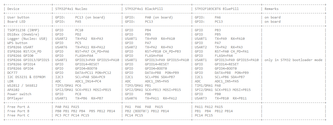
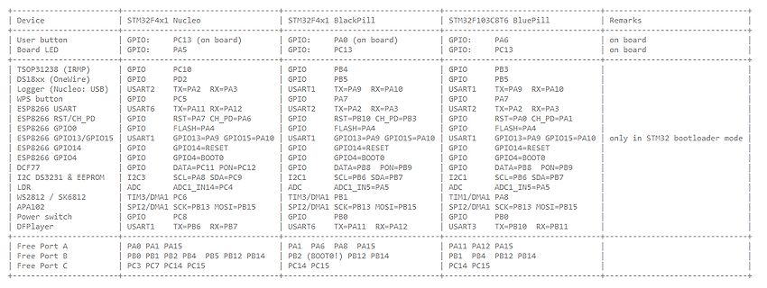
Tabelle mit Pinbelegungen verschiedener Mikrocontroller-Boards
BOOT0 | DCF77 | GPIO: DATA=PC11 PON=PC12 | GPIO: DATA=PB6 PON=PB9 | GPIO: DATA=PB8 PON=PB9 | I2C DS3231 & EEPROM | I2C3: SCL=PB8 SDA=PB9 | I2C1: SCL=PB6 SDA=PB7 | I2C1: SCL=PB6 SDA=PB7 | ADC | ADC: ADC1_IN1=PC
in „WordClock mit WS2812“ · Projekte & Code · · Screenshots
-
Datei
TextWithArduinoGraphics_RTC_Fertig_ohne_Serial.print.ino
Arduino_LED_Matrix.h" ArduinoLEDMatrix matrix; //End Led-Matrix //Begin RTC #include "RTClib.h" RTC_DS3231 rtc; char daysOfTheWeek[7][12] = { "Sonntag", "Montag", "Dienstag", "Mittwoch", "Donnerstag", "Freitag", "Samstag" }; // End RTC /************************************************************** DateTime
in „RTC DS3231 (EOSC) Uhrzeit läuft nicht weiter, nur mit Knopfzelle“ · Mikrocontroller und Digitale Elektronik ·
-
Datei
Print_test_Function_call.ino
#include <SPI.h> #include <Wire.h> #include "DS3231.h" #include <Adafruit_GFX.h> #include <Adafruit_SSD1306.h> #include "thermalprinter.h" #define SCREEN_WIDTH 128 // OLED display width, in pixels #define SCREEN_HEIGHT 64 // OLED display height, in
in „Arduino: Ausgabe Zeit als Funktionsaufruf für mehreren "Devices"“ · Mikrocontroller und Digitale Elektronik ·
-
Datei
bb_i2c.h
twi_port,twi_pin_sda) #define change_d_out pinDIRout(twi_port,twi_pin_sda) /* adressen: twi-lcd: 64 ds3231: 0x68 / 104 si4703: 32 */ //========================================== void i2c_WriteBit(unsigned char ccc) { _delay_us(1); if(ccc){data_h;} else {data_l;} _delay_us(1); clock_h; _delay_us(1); clock_l
in „stm32f103 i2c_read“ · Mikrocontroller und Digitale Elektronik ·
-
Datei
I2C_TWI0_Address_and_Frequency_Scanner.ino
U10: AT24C256 (256K EEprom) I2C device found at address 0x68 = B0110.1000 = B1101.000x ... U11: DS3231 (RTC) I2C device found at address 0x73 = B0111.0011 = B1110.011x ... U7: PCA9538D (Portexpander) I2C device found at address 0x7C = B0111.1100 = B1111.100x ... U6: PCA8574D (Portexpander) ??? */ #include
in „NXP PCA8574 hat Phänomen mit 2 Adressen“ · Mikrocontroller und Digitale Elektronik ·
-
Datei
test99.cc
sport.h> #include <external/hal/adccontroller.h> #include <etl/meta.h> #include "hc05.h" #include "ds3231.h" #include "ssd1306.h" using namespace std::literals::chrono; using namespace External::Units::literals; template<auto HWRev = 0, typename MCU = DefaultMcuType> struct Devices; // HWRev 6 template
in „C++ in (deeply) Embedded Systemen für Neuprojekte“ · Mikrocontroller und Digitale Elektronik ·
-
Datei
MultiSpeedI2CScanner.ino
] = "0.1.06"; // scans devices from 50 to 800KHz I2C speeds. // lower than 50 is not possible // DS3231 RTC works on 800 KHz. TWBR = 2; (?) const long allSpeed[] = { 50, 100, 200, 250, 400, 500, 800 }; long speed[sizeof(allSpeed) / sizeof(allSpeed[0])]; int speeds; int addressStart = 0; int addressEnd
in „Probleme mit meinem LCD-Display“ · Mikrocontroller und Digitale Elektronik ·
-
Datei
MultiSpeedI2CScanner.ino
] = "0.1.06"; // scans devices from 50 to 800KHz I2C speeds. // lower than 50 is not possible // DS3231 RTC works on 800 KHz. TWBR = 2; (?) const long allSpeed[] = { 50, 100, 200, 250, 400, 500, 800 }; long speed[sizeof(allSpeed) / sizeof(allSpeed[0])]; int speeds; int addressStart = 0; int addressEnd
in „i2c & LCD stellt sich quer :/“ · Mikrocontroller und Digitale Elektronik ·
-
Datei
MultiSpeedI2CScanner.ino
] = "0.1.06"; // scans devices from 50 to 800KHz I2C speeds. // lower than 50 is not possible // DS3231 RTC works on 800 KHz. TWBR = 2; (?) const long allSpeed[] = { 50, 100, 200, 250, 400, 500, 800 }; long speed[sizeof(allSpeed) / sizeof(allSpeed[0])]; int speeds; int addressStart = 0; int addressEnd
in „ADS1115 lässt Arduino Uno einfrieren“ · Mikrocontroller und Digitale Elektronik ·
-
Datei
UhrWS2812.ino
/** * NeoClock * * Clock using 60 WS2812B/Neopixel LEDs and DS3231 RTC * * Libraries needed: * * Adafruit NeoPixel (Library Manager) - Phil Burgess / Paint Your Dragon for Adafruit Industries - LGPL3 * * Rtc by Makuna (Library Manager) - Michael C. Miller * * Arduino
in „LED Uhr mit RTC braucht Taster“ · Mikrocontroller und Digitale Elektronik ·
-
Datei
bb_i2c_arm.c
pinDIRout(twi_port,twi_pin_sda) //#define data_in pinVAL(twi_port,twi_pin_sda) /* adressen: twi-lcd: 64 ds3231: 0x68 / 104 si4703: 32 */ //bei 72Mhz F_CPU=6536 #define xF_DELAY 6536 void _delay_us(long us){//genau auf 100sec uint32_t i,j=xF_DELAY*us/1000; for(i=0;i<j;i++); } //==============================
in „stm32f103 i2c_read“ · Mikrocontroller und Digitale Elektronik ·
-
Datei
main.cpp
t state = STARTUP; uint8_t btn_state = BTN_INAKTIV; uint32_t time_stamp = 0; uint8_t result; RTC_DS3231 rtc; DateTime now; uint8_t ps; uint8_t apis; uint16_t session_timeout; unsigned long prev_time; uint8_t get_pump_state() { /* return current state of the pump based on time and day given time should
in „Absturz beim ESP8266“ · Mikrocontroller und Digitale Elektronik ·
-
PDF
Private_Entruempelung_des_Bastel-Lagers.pdf
Zusammen 20€ #50 – Relaiskarten • 2x 8er • 3x 4er • Zusammen 15€ #51 – Keypad 4x4 • Zusammen 9€ #52 – DS3231 RTC • 3x RTC • 2x SD-Adapter Breakout • Zusammen 10€ #53 – TFT Displays • 5x vorhanden • 1.8“ TFT 128x160 Pixel • SPI Interface • Zusammen 15€ #54 – uBlox NEO-7M GPS Modul • 4x vorhanden • Inkl. Breakout
-
PDF
Private_Entruempelung_des_Bastel-Lagers_V2.pdf
Zusammen 20€ #50 – Relaiskarten • 2x 8er • 3x 4er • Zusammen 15€ #51 – Keypad 4x4 • Zusammen 9€ #52 – DS3231 RTC • 3x RTC • 2x SD-Adapter Breakout • Zusammen 10€ #53 – TFT Displays • 5x vorhanden • 1.8“ TFT 128x160 Pixel • SPI Interface • Zusammen 15€ #54 – uBlox NEO-7M GPS Modul • 4x vorhanden • Inkl. Breakout
-
PDF
Private_Entruempelung_des_Bastel-Lagers_V3.pdf
Zusammen 20€ #50 – Relaiskarten • 2x 8er • 3x 4er • Zusammen 15€ #51 – Keypad 4x4 • Zusammen 9€ #52 – DS3231 RTC • 3x RTC • 2x SD-Adapter Breakout • Zusammen 10€ #53 – TFT Displays • 5x vorhanden • 1.8“ TFT 128x160 Pixel • SPI Interface • Zusammen 15€ #54 – uBlox NEO-7M GPS Modul • 4x vorhanden • Inkl. Breakout
-
PDF
Private_Entruempelung_des_Bastel-Lagers_V4.pdf
Zusammen 20€ #50 – Relaiskarten • 2x 8er • 3x 4er • Zusammen 15€ #51 – Keypad 4x4 • Zusammen 9€ #52 – DS3231 RTC • 3x RTC • 2x SD-Adapter Breakout • Zusammen 10€ #53 – TFT Displays • 5x vorhanden • 1.8“ TFT 128x160 Pixel • SPI Interface • Zusammen 15€ #54 – uBlox NEO-7M GPS Modul • 4x vorhanden • Inkl. Breakout
-
Datei
dcf_az.ino
, 4); #define STATUS_PIN LED_BUILTIN #define DCF_PIN 2 #include <wire.h> #include "RTClib.h" RTC_DS3231 rtc; int HIGH_Start = 0; int HIGH_Ende = 0; int HIGH_Zeit = 0; int LOW_Start = 0; int LOW_Ende = 0; int LOW_Zeit = 0; int ZONE = 0; int disp=0; bool Signal = false; bool neueMinute = false; int BIT
in „Arduino und Atmega8“ · Mikrocontroller und Digitale Elektronik ·
-
PDF
CamperDisplay.pdf
EXTRESET U14 4 6 8 9 1 GND P5 X - OUT25 OUTWASTE 1 CLK SCL 8 SCL 2 3 4 2 1 0 WATERREF 0R0 4 - V 2 VCC DS3231 SDA 7 D D D A MOS2 IN BTS410 2 N R20 100nF 2 LM339 C15 3 6 SDA 10nF 7 p D 7 V V V D K 8 3 VDD N 1 INT VBAT C 2 G 10K NRST V 1 R 4 O 4 RST U8 GND 5 BT1 D R8 STATUS U4 C C42 100nF 44 10 5 VOUT +3,3V
in „Akku und Wasserstandsdisplay für Wohnmobile“ · Projekte & Code ·
-
PDF
12062017_Schaltplan.pdf
3 C 1 3 1 (TXD)PD1 15 D MSTBV4 R R C (RXD)PD0 14 max. 300 uA / SMBUS D +5V Temp/RH MEGA32-P U1 u DS3231 V 1 , + SDA X15-1 VIN+ VIN- 0 16 1 C4 2 VS VBUS SCL 32KHZ 9 . 8 . F SCL X15-2 ALERT A1 15 2 R 2 R 2 0 3 SDA A0 I2C - SLAVE ADDRESS SDA VCC 1 8 IC41 GND/2.2C X15-3 SCL GND 1000000 VDD2 VDD1 14 VBAT
in „Messtechnische Schaltung mit uC“ · Mikrocontroller und Digitale Elektronik ·
-
Datei
serialevent.ino
0, 0, 0, 0, 5, 1, 2, 10000, 100, 0, 0, 0, 0, 0, 5, 1, 2, 10000, 100, 0, 0, 0, 0}; //RTC&Zeit RTC_DS3231 RTC; String filename = ""; void setup() { loadconfigs(); Serial.begin(115200); if (! RTC.begin()) {} setSyncProvider(syncProvider); setSyncInterval(1000); if (!SD.begin(chipSelect)) { Serial.println
-
Datei
main.c
//#include "max5717.h" // DAC-Funktionen //#include "sram23lcv.h" // SRAM-Funktionen //#include "ds3231.h" // RTC-Funktionen //#include "lcd44780.h" // LCD-Funktionen #include "out.h" // Zahlenausgabe USART/LCD //#include "i2c.h" // SPI-Funktionen - fuer i2c_init() #include "usb_serial.h" // USB-Funktionen
in „Atmega32U4-Board: USB-Ausgabe in Betrieb nehmen“ · Mikrocontroller und Digitale Elektronik ·
-
Datei
Plotclock_v1_2.ino
http://www.pjrc.com/teensy/td_libs_DS1307RTC.html // DS1307RTC works with the DS1307, DS1337 and DS3231 real time clock chips. // Please run the SetTime example to initialize the time on new RTC chips and begin running. #include <Wire.h> #include <DS1307RTC.h> // see http://playground.arduino.cc/Code
in „Plotclock zusammenbauen und programmieren“ · Mikrocontroller und Digitale Elektronik ·
-
Datei
web_services.cpp
extern uint16_t start_time[7]; extern uint16_t stop_time[7]; extern uint8_t status[7]; extern RTC_DS3231 rtc; String file_data; uint8_t reponded = 0; const char header_html[] PROGMEM = R"rawliteral( <!DOCTYPE HTML> <html> <head> <meta name="viewport" content="width=device-width, initial-scale=1"> <style
in „Absturz beim ESP8266“ · Mikrocontroller und Digitale Elektronik ·
-
Datei
code.c
DCF_INTERRUPT 0 // Interrupt number associated with pin #define LDR_PIN 0 //dcf variables DateTime time; RTC_DS3231 rtc; DCF77 DCF = DCF77(DCF_PIN, DCF_INTERRUPT); uint8_t strip[NUM_LEDS]; uint8_t secondColorStrip[NUM_LEDS]; uint8_t stackptr = 0; CRGB leds[NUM_LEDS]; IRrecv irrecv = IRrecv(IR_RECV_PIN); decode_results
in „Arduino hängt sich auf (Wordclock)“ · Mikrocontroller und Digitale Elektronik ·
-
PDF
Forum.PDF
PI1rc4 C11 Pt Pt COJ0rc+3.3 C 6 P BT1_rtc J1_rtc PU0rc2VCC GND PI1rc1 Pt 2 120591-1 1025-7 2 F P2 DS3231S# +3.3 0 Pt 1 c C r 0 C C02 1 GND GND GND GND C n 0 1 1 U1_rtcB P PU0rc5 NC NC PI1rc0 P PU0rc6 PI1r0c 2 PU0rc7 NC NC PI1rc1 8 NC NC 12 PU0rc8 NC NC PI1rc1 DS3231S# GND GND GND D Title D Size Number
in „Raspberry Pi Compute Module 3 (Carrier Board)“ · Mikrocontroller und Digitale Elektronik ·
-
PDF
Forum.PDF
PI1rc4 C11 Pt Pt COJ0rc+3.3 C 6 P BT1_rtc J1_rtc PU0rc2VCC GND PI1rc1 Pt 2 120591-1 1025-7 2 F P2 DS3231S# +3.3 0 Pt 1 c C r 0 C C02 1 GND GND GND GND C n 0 1 1 U1_rtcB P PU0rc5 NC NC PI1rc0 P PU0rc6 PI1r0c 2 PU0rc7 NC NC PI1rc1 8 NC NC 12 PU0rc8 NC NC PI1rc1 DS3231S# GND GND GND D Title D Size Number
in „Raspberry Pi Compute Module 3 (Carrier Board)“ · Mikrocontroller und Digitale Elektronik ·
-
Datei
log.txt
RTC test for DS3231 via I2C 20:49:15 Thursday 24.08.2023 Temp: 31.75 Age Offset: 0 20:49:16 Thursday 24.08.2023 Temp: 31.75 Age Offset: 0 20:49:17 Thursday 24.08.2023 Temp: 31.75 Age Offset: 0 20:49:18 Thursday 24.08.2023
in „DS3231SN RTC Module mit DS3231M (MEMS) Typ installiert“ · Mikrocontroller und Digitale Elektronik ·
-
Datei
beispiel.html
</b></span> - <span style="color: blue;"><b> DS1803 </b></span> - <span style="color: blue;"><b> DS3231N </b></span> - <span style="color: blue;"><b> PCA9535 </b></span> - <span style="color: blue;"><b> TLE-4242-G </b></span> - <span style="color: blue;"><b> ULN2803 </b></span> OK </li> </ul> kicadlib.org
in „[KiCad] Bibliotheksaufbau - Konzeptideen gesucht“ · Platinen ·
-
PDF
PicoMite_User_Manual.pdf
Interface Using the RTC GETTIME command it is easy to get the current time from a PCF8563, DS1307, DS3231 or DS3232 real time clock as well as compatible devices such as the M41T11. These integrated circuits are popular and cheap, will keep accurate time even with the power removed and can be purchased
in „allgemeine PicoMite Anfängerfragen“ · Mikrocontroller und Digitale Elektronik ·
-
PDF
PicoMite_User_Manual_4_.pdf
Interface Using the RTC GETTIME command it is easy to get the current time from a PCF8563, DS1307, DS3231 or DS3232 real time clock as well as compatible devices such as the M41T11. These integrated circuits are popular and cheap, will keep accurate time even with the power removed and can be purchased
in „Qual der Wahl - Sensoren Auswertung auf Display ("Analog")“ · Mikrocontroller und Digitale Elektronik ·
-
PDF
kicad_8450_dcm_liste_neu_v3.pdf
information-storag 3.0V - 4.5V VDD DS28EA00 1-Wire Digital Thermometer with Sequence Detect and PIO DS3231 Extremely Accurate I2C-Integrated RTC/TCXO/Crystal SOIC-16 DS3231MZ ±5ppm, I2C Real-Time Clock SOIC-8 DS3232M ±5ppm, I2C Real-Time Clock with SRAM SOIC-8 MAX1248 4-Channel 10-Bit ADC with Serial Interface
in „KiCAD Eeschema, Bibliotheksdokumentation *.dcm als PDF-Datei“ · Platinen ·