-
PDF
WS2812B.pdf
WS2812B Intelligent control LED integrated light source Features and Benefits Intelligent reverse connect protection, the power supply reverse connection does not damage the IC. The control circuit and
in „ESP32-H2 will nicht schlafen“ · Mikrocontroller und Digitale Elektronik ·
-
PDF
Schaltung_LPC.pdf
PEGELWANDLER 4 L 5 L 6 L 4 L 5 L 6 L DCPRG 23 DCPRG OUT9 17 L4_G LED_DATA_3V3 2 18D LED_DATA DIN WS2812B DOUT DIN WS2812B DOUT DIN WS2812B DOUT VPRG 6 XERR OUT10 18 L4_B 3 A1 B1 17 27 VPRG OUT11 19 L5_R 4 A2 B2 16 IREF OUT12 20 L5_G 5 A3 B3 15 S S S OUT13 21 L5_B 6 A4 B4 14 V V V 2k2 1 GND OUT15 22 L6
in „LPC1756 - WS2812B und Schaltplankontrolle“ · Mikrocontroller und Digitale Elektronik ·
-
Datei
README.txt
===== ----- FILES ============================================================================== ws2812.h Public definitions for using the driver, here you can do some customization if required (ie. change the timing etc.). ws2812test.c Quick'n'dirty test program, doing some chasing light if you have some LEDs as strip ws2812_tinymega.s Implementation for ATtiny and ATmega ws2812_xmega.s Implementation for ATxmega asmdefs.h Used in the ASM source, implements some handy macros gammacorrection.h Some definitions for gamma
in „AVR ASM ws2811 / ws2812 Ansteuerung mit FastPWM“ · Projekte & Code ·
-
Datei
ws2812.c
/****************************** File: ws2812.c ********************************* * Author : wizard2001 22.03.2023 * Version : V1.0.0 * Settings : MounRiver Studio V1.84 MCU CH32V003F4P6 CH32F003_Board SSOP20 * Description : Control WS2812 Chain
in „Problem: CH32V003 läst sich nicht (mehr) flashen“ · Mikrocontroller und Digitale Elektronik ·
-
PDF
WS2812B-V5.pdf
WS2812B Ver. No.: V5 Intelligent control LED integrated light source Features and Benefits The control circuit and the LED share the only power source. Control circuit and RGB chip are integrated in a
in „PWM-Signal verstärken“ · Mikrocontroller und Digitale Elektronik ·
-
PDF
WS2812B-V5.pdf
WS2812B Ver. No.: V5 Intelligent control LED integrated light source Features and Benefits The control circuit and the LED share the only power source. Control circuit and RGB chip are integrated in a
in „WS2812B mit 3.3V ansteuern“ · Mikrocontroller und Digitale Elektronik ·
-
PDF
WS2812B__Ver._No._V5__EN_19112715001349.pdf
WS2812B Ver. No.: V5 Intelligent control LED integrated light source Features and Benefits The control circuit and the LED share the only power source. Control circuit and RGB chip are integrated in a
in „Adressierbare RGB LEDs 3.3V gesucht“ · Mikrocontroller und Digitale Elektronik ·
-
PDF
WS2812B_Datasheet_2017.pdf
WS2812B Intelligent control LED integrated light source Features and Benefits The control circuit and the LED share the only power source. Control circuit and RGB chip are integrated in a package of 5050
in „WS2812 Ansteuerung“ · Mikrocontroller und Digitale Elektronik ·
-
PDF
WS2812B-MINI.pdf
WS2812B-Mini Intelligent external control LED Integrated light source Features and Benefits The IC’s control circuit and the LED share the same power supply. Control circuit and RGB chip are integrated
in „Indirekte Beleuchtung mit ca. 30m LED Streifen“ · Analoge Elektronik und Schaltungstechnik ·
-
Datei
WS2812.cpp
using the fast 800kHz clockless WS2811/2812 protocol. Based on https://github.com/cpldcpu/light_ws2812 From Tim cpldcpu */ #include "WS2812.h" // Timing in ns #define w_zeropulse 350 #define w_onepulse 900 #define w_totalperiod 1250 void ws2812_init() { ws2812_DDREG |= mask; // Enable DDR } #define
in „Hab meinen MPP(T) akkulader probiert :)“ · Mikrocontroller und Digitale Elektronik ·
-
Datei
ws2812.c
/****************************** File: ws2812.c ********************************* * Author : Reinhard 23.04.2025 * Version : V1.0.0 * Settings : MounRiver Studio MCU CH32X035 * Description : Ansteuerung WS2812/WS2815 per SPI * PA.7(SPI-MOSI) - WS2812/WS2815 Data * ******************************************************************************/ //--------------------------- Includes #include "debug.h" #include "ws2812.h" #include "gpio_def_x035.h
in „CH32V003 / SPI und Gehäuse SOP-16“ · Mikrocontroller und Digitale Elektronik ·
-
Datei
ws2812_sendarray.asm
temporäres Register .DEF loopcounter = r17 ;Schleifenzähler ;Hier Port und Pin festlegen, an denen die WS2812 angeschlossen ist: .EQU led_port = PORTx ;WS2812 relevantes PORT Register .EQU led_ddr = DDRx ;WS2812 relevantes Data Direction Register .EQU led_pin = PDx ;WS2812 relevanter I/O Pin ;Hier die Anzahl
in „Lightweight WS2811/WS2812 Library“ · Mikrocontroller und Digitale Elektronik ·
-
PDF
WS2812B-V4.pdf
WS2812B-V4 Intelligent control LED integrated light source Features and Benefits The control circuit and the LED share the only power source. Control circuit and RGB chip are integrated in a package of
in „PWM-Signal verstärken“ · Mikrocontroller und Digitale Elektronik ·
-
Datei
main.c
/* * Light_WS2812 library example - RGB_blinky * * cycles one LED through red, green, blue * * This example is configured for a ATtiny85 with PLL clock fuse set and * the WS2812 string connected to PB4. */ #define F_CPU
in „Lightweight WS2811/WS2812 Library“ · Mikrocontroller und Digitale Elektronik ·
-
Datei
WS2812.h
#define WS2812_LAT LATAbits.LATA4 #define WS2812_TRIS TRISAbits.TRISA4 void WS2812_Init(void); void WS2812_Write(unsigned char *data, int number_leds); inline void WS2812_WriteBit(unsigned char DataBit);
in „[ASM & C] PIC12/PIC18/PIC24 WS2812 SPI Library“ · Projekte & Code ·
-
Datei
WS2812Ctrl.cpp
/*----------------------------------------------------------------------- WS2812Ctrl.c Control of LED Strip with WS2812B driver ----------------------------------------------------------------------- Last committed: $Revision: 05 $ Last changed by: $Author: Thomas.Stief@web.de$
-
Bild
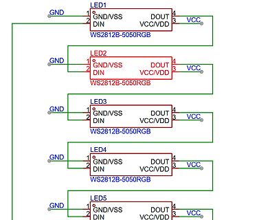
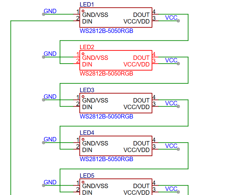
Schaltplan mit fünf WS2812B-5050RGB LEDs
LED1 WS2812B-5050RGB GND/VSS DIN DOUT VCC/VDD VCC GND LED2 WS2812B-5050RGB GND/VSS DIN DOUT VCC/VDD VCC GND LED3 WS2812B-5050RGB GND/VSS DIN DOUT VCC/VDD VCC GND LED4 WS2812B-5050RGB GND/VSS DIN DOUT VCC/VDD VCC GND LED5 WS2812B-5050RGB GND/VSS DIN DOUT VCC/VDD VCC GND
in „ESP32 und 240Stück WS2812B“ · Mikrocontroller und Digitale Elektronik · · Schaltpläne
-
Datei
main24.s
address ws2812loop_1: mov.b [w1++],w2 mov #4,w4 ws2812loop_2: mov #0xF0F0,w0 ;Send 2x '1' btss w2,#7 mov.b #0xC0,w0 ;Send '0' swap w0 ;Swap byte W0 btss w2,#6 mov.b #0xC0,w0 ;Send '0' rlnc w2,w2 rlnc w2,w2 btsc SPI1STAT,#SPITBF ;Wait for transmission finished. bra $-2 mov w0,SPI1BUF dec w4,w4 bra nz,ws2812loop_2 cp w1,w3 ;Compare curent RGB_byte address with ast RGB_byte addres bra lt,ws2812loop_1 ;bra if less then return .end
in „[ASM & C] PIC12/PIC18/PIC24 WS2812 SPI Library“ · Projekte & Code ·
-
Datei
main.c
ifndef F_CPU #error please define F_CPU with the correct clock-frequency of your MCU #endif #include "ws2812.h" #include <stdlib.h> #include <stdio.h> #include <stdbool.h> #include <stdint.h> #include <inttypes.h> #include <string.h> #include <alloca.h> #include <avr/io.h> #include <avr/wdt.h> #include <avr
in „AVR ASM ws2811 / ws2812 Ansteuerung mit FastPWM“ · Projekte & Code ·
-
Datei
WS2812_Glediator.ino
of WS2812 pixels # // # // Adjust the correct DATA PIN and the correct NUMBER OF PIXELS you are using # // in the definitions section below before uploading this sketch to your # // Arduino device. # // # //
in „Auswahl zweier Arduino Sketches“ · Mikrocontroller und Digitale Elektronik ·
-
Bild
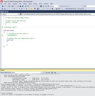
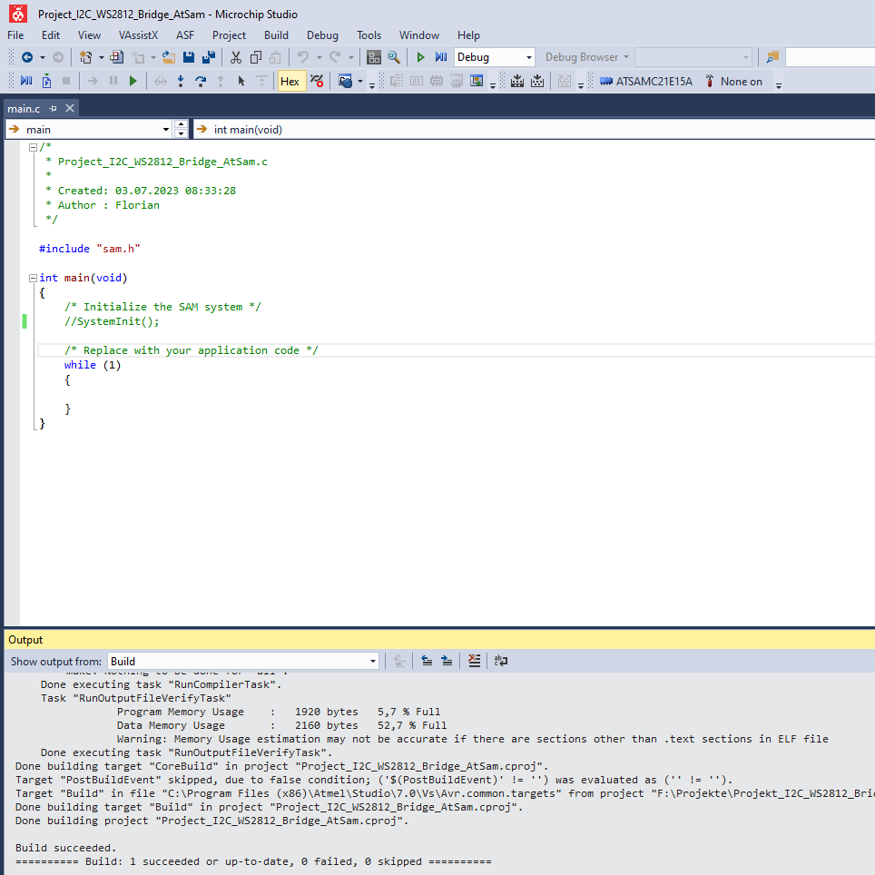
Screenshot der Microchip Studio Entwicklungsumgebung
Project_I2C_WS2812_Bridge_AtSam - Microchip Studio File Edit View VassistX ASF Project Debug Tools Help Debug ATSAMC21E15A main.c int main(void) #include "sam.h" /* Initialize the SAM system */ /* Replace with your application
in „Unrealistische Recourcenauslastung bei leerem Projekt“ · Mikrocontroller und Digitale Elektronik · · Screenshots
-
Datei
ws6812_test_zwo.c
ANZAHL_LEDS 525 #include <util/delay.h> #include <avr/io.h> #include <avr/interrupt.h> #include "light_ws2812.h" struct cRGBW led[ANZAHL_LEDS]; int main(void) { while(1) { for (uint16_t i = 0; i < ANZAHL_LEDS; i++) { led[i].r=128;led[i].g=00;led[i].b=0;led[i].w=0; // Write red to array } ws2812_setleds_rgbw
in „atmega328; data memory voll, wie umlagern“ · Mikrocontroller und Digitale Elektronik ·
-
Datei
WS2812.cpp
RGB values to the Dataout port using the fast 800kHz clockless WS2811/2812 protocol. */ #include "WS2812.h" // Timing in ns #define w_zeropulse 350 #define w_onepulse 900 #define w_totalperiod 1250 void ws2812_init() { ws2812_DDREG |= mask; // Enable DDR } #define w_nop1 "nop \n\t" #define w_nop2 "rjmp
in „Ein "non bloated" arduino 328p WS2812 treiber“ · Projekte & Code ·
-
Datei
main.c
power.h" #include "delay.h" #if WCLOCK24H == 1 #include "tables.h" #endif #include "log.h" #include "ws2812/ws2812.h" #define VERSION "2.0.3" // 2016-06-21 typedef enum { aus = 0, gelb = 1, blau = 2, weiss = 3, grau = 4, }FARBCODE; static const WS2812_RGB FARBE_SCHWARZ = {0, 0, 0}; static const WS2812_RGB FARBE_GELB = {241, 205, 60}; static const WS2812_RGB FARBE_BLAU = {5, 9, 163}; static const WS2812_RGB FARBE_WEISS = {200, 200, 200}; static const WS2812_RGB FARBE_GRAU = {70, 70, 70}; /* FARBCODE anzeige[114] = { aus, aus, aus, aus, aus, aus, aus
-
PDF
WS2812.pdf
WS2812 Intelligent control LED integrated light source Features and Benefits l Control circuit and RGB chip are integrated in a package of 5050 components, form a complete control of pixel point. l Built-in
in „WS2812/2811 mit PIC asm.Verzweiflung!“ · Mikrocontroller und Digitale Elektronik ·
-
PDF
WS2812preliminary.pdf
WS2812 Intelligent control LED integrated light source Features and Benefits l Control circuit and RGB chip are integrated in a package of 5050 components, form a complete control of pixel point. l Built-in
in „[Mitbestellung] SMD5050 RGB-LED mit integriertem 8-bit PWM Controller“ · Markt ·
-
PDF
WS2812.pdf
WS2812 Intelligent control LED integrated light source Features and Benefits l Control circuit and RGB chip are integrated in a package of 5050 components, form a complete control of pixel point. l Built-in
in „Kabelquerschnitt für 5V?“ · Analoge Elektronik und Schaltungstechnik ·
-
PDF
WS2812preliminary.pdf
WS2812 Intelligent control LED integrated light source Features and Benefits l Control circuit and RGB chip are integrated in a package of 5050 components, form a complete control of pixel point. l Built-in
in „WS2812 Timing“ · Mikrocontroller und Digitale Elektronik ·
-
Datei
ws2812c.asm
;WS2812 CONTROL ;--------------------------------------------------------------------------------- ;USING ATTINY1614 @ 5V/20MHz, WS2812B LED STRIP ;FUSE: INT.RC OSC20 ;PORT-Belegung: I/O-A0: UPDI INP-B0: ;
in „WS2812 control @ ATTiny1614 (Assembler)“ · Projekte & Code ·
-
PDF
Schaltplan.pdf
3 4 5 6 7 8 A A U1 ESP32-WROOM-32D(16MB) B GND 39 GND B GND 1 38 2 GND GND 37 GND VCC VDD33 IO23 WS2812 Ch3 EnableEN IO22 36 SCL 12V Input SENSOR_VP TXD0 35 TX 12V Input Rot 34 6 SENSOR_VN RXD0 33 RX 12V Inpu7 IO34 IO21 32 SDA 5v InputIO35 NC nicht verbunden 5v Input GIO32 IO19 31WS2812 Ch4 12 V Output
in „LD1117 3.3 V wird warm“ · Analoge Elektronik und Schaltungstechnik ·
-
Datei
C_Programm.c
/* * Light_WS2812 library example - RGB_blinky * * cycles one LED through red, green, blue * * This example is configured for a ATtiny85 with PLL clock fuse set and * the WS2812 string connected to PB4. */ # define
in „ws2812 mit atmega32“ · Mikrocontroller und Digitale Elektronik ·
-
Bild
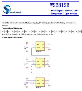
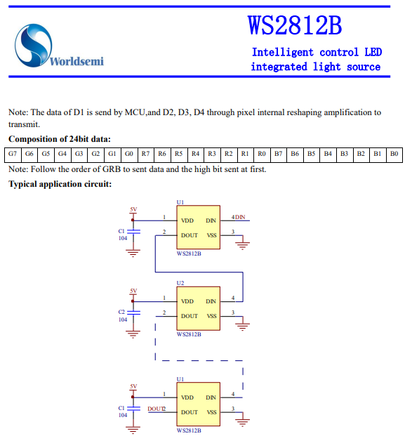
Datenblatt Ausschnitt WS2812B LED Treiber
WS2812B Intelligent control LED integrated light source Note: The data of D1 is send by MCU,and D2, D3, D4 through pixel internal reshaping amplification to transmit. Composition of 24bit data: G7 G6 G5 G4
in „Problem mit WS2812b 4-Layer Board“ · Mikrocontroller und Digitale Elektronik · · Screenshots
-
PDF
4xRGB-LED-Steuern-5V_SCH.PDF
- 2 2 2 2 + 0 3- 1 7 2 7 3 7 4 7 2 R 4 R 4 R 1 4 R 4 1+ 1 1 1 K2 RGB-LED Daten Klemme 4 3 2 1 K3 WS2812B 3 VSS Dout 2 4 Din VDD 1 D4 WS2812B VSS Dout 3 2 4 Din VDD 1 D3 WS2812B 3 VSS Dout 2 Din VDD 4 1 D2 WS2812B VSS Dout 3 2 4 Din VDD 1 D1
in „empehlung Microcontroller WS2812B Steuern“ · Mikrocontroller und Digitale Elektronik ·
-
Bild
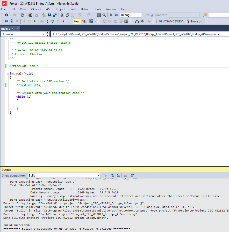
Microchip Studio Code-Editor und Build-Ausgabe
Project_I2C_WS2812_Bridge_AtSam - Microchip Studio File Edit View VAssistX ASF Project Build Tools Window Help main.c /* * Project_I2C_WS2812_Bridge_AtSam.c * Created: 03.07.2023 08:33:28 * Author: Florian */ //#
in „Unrealistische Recourcenauslastung bei leerem Projekt“ · Mikrocontroller und Digitale Elektronik · · Screenshots
-
Datei
installation_lauflicht.c
include <avr/io.h> #include <avr/interrupt.h> #include <stdio.h> #include <stdlib.h> #include "light_ws2812.h" #define WHITE_LIGHT PORTD3 //weiße LED-Kette #define STATUS_LED PORTD4 //Status/Test-Led #define RESERVE PORTD5 //frei #define WS2812_RESERVE PORTD6 //Reserve für evtl. zweite WS2812-Kette //ws2812
in „HCSR04-US-Sensoren an Atmega328P kurioser Effekt // Entstörung“ · Mikrocontroller und Digitale Elektronik ·
-
Datei
installation_lauflicht.c
include <avr/io.h> #include <avr/interrupt.h> #include <stdio.h> #include <stdlib.h> #include "light_ws2812.h" #define WHITE_LIGHT PORTD3 //weiße LED-Kette #define STATUS_LED PORTD4 //Status/Test-Led #define RESERVE PORTD5 //frei #define WS2812_RESERVE PORTD6 //Reserve für evtl. zweite WS2812-Kette //ws2812
in „Atmega328P: PB6/PB7 als I/O nutzen“ · Mikrocontroller und Digitale Elektronik ·
-
Datei
LED_WS2812B.c
/pgmspace.h> #include "light_ws2812.h" uint16_t sample; // Byte-Nummer der LED struct cRGB led[5]; //Stuktur der Header-Datei definieren. Nur die LED-Anzahl angeben. uint8_t i=0; //Schleifenvariable int color_def=134; unsigned char color_data
in „WS2812 Ansteuerung per Bitbanging für AVR und ARM von 4 Mhz-60 Mhz“ · Projekte & Code ·
-
Datei
ws2812_config.h
settings. #define w_lowtime ((w1_nops+w_fixedlow)*1000000)/(F_CPU/1000) #if w_lowtime>550 #error "Light_ws2812: Sorry, the clock speed is too low. Did you set F_CPU correctly?" #elif w_lowtime>450 #warning "Light_ws2812: The timing is critical and may only work on WS2812B, not on WS2812(S)." #warning "Please
in „WS2812b LED-streifen aktualisiert sich erst nach zweitem aufruf“ · Mikrocontroller und Digitale Elektronik ·
-
Datei
LED_WS2812B.c
############################################################################# // Steuerung von 5 WS2812B über einen beliebigen Port //################################################################################### #include <avr/io.h> #include <util/delay.h> #include <avr/pgmspace.h> #include "light_ws2812
in „WS2812 Ansteuerung per Bitbanging für AVR und ARM von 4 Mhz-60 Mhz“ · Projekte & Code ·
-
Datei
ws6812_test_zwo.c
= ring_green; led[pixel[zeile_akt][i]].b = ring_blue; led[pixel[zeile_akt][i]].w = ring_white; } ws2812_setleds_rgbw(led,ANZAHL_LEDS); zeile_akt++; } } int main(void) { create_matrix(ANZAHL_ZEILEN, ANZAHL_SPALTEN); while(1) { fill_background(0,0,0,0); ws2812_setleds_rgbw(led,ANZAHL_LEDS); _delay_ms(500
in „LED-Matrix mit light_ws2812-library; Ansteuerungsgeschwindigkeit“ · Mikrocontroller und Digitale Elektronik ·
-
Datei
tetris_io.c
--------------------------------------- */ #include "Project.h" #include "tetris_io.h" #include "ws2812.h" /* stores the color (number) of every pixel */ uint8_t TRIS_pixelArrey[GRID_DX][GRID_DY]; static void TRIS_SetPixel(uint_fast8_t x, uint_fast8_t y, uint_fast8_t color) { /* check array borders *
in „ein plattformunabhängiger Tetris-Clone“ · Projekte & Code ·
-
Datei
led_modes.c
/* * led_modes.c * * Created: 05.05.2016 23:25:26 * Author: Hannes */ #include "includes/light_ws2812.h" #include <math.h> #include <stdlib.h> #define MAX 255 #define BASE 10 #define RESOLUTION 64 //number of steps to increment the brightness value #define NOF_COLORS 14 #define NOF_MODES (NOF_COLORS
in „Code zu groß für AtTiny45“ · Mikrocontroller und Digitale Elektronik ·
-
Datei
ws2812b.h
#ifndef WS2812B #define WS2812B #ifdef STM32F10X_MD #include <stm32f10x.h> #include <irq_stm32f103.h> #endif #if defined(STM32F303xE) || defined(STM32F303xD) || defined(STM32F303xC) #include <stm32f3xx.h> #include
in „WS2812b Pixel mit STM32 und PWM/DMA ohne Hal“ · Mikrocontroller und Digitale Elektronik ·
-
Datei
main.c
We are running at 48 MHz, so set divider to /16, so we have 0.33 us bit length == 1 MHz clock for WS2812 */ SPI1->CR1 = SPI_CR1_BIDIMODE|SPI_CR1_BIDIOE|SPI_CR1_SPE|SPI_CR1_BR_0|SPI_CR1_BR_1|SPI_CR1_MSTR|SPI_CR1_SSM|SPI_CR1_SSI; SPI1->CR2 = SPI_CR2_DS_0|SPI_CR2_DS_1|SPI_CR2_DS_2|SPI_CR2_TXDMAEN; // LED
in „The secret of WS2812B“ · Mikrocontroller und Digitale Elektronik ·
-
Datei
main.c
include <stdlib.h> #include <string.h> #include "UART.h" #include "LCD.h" #include "site.h" #include "WS2812.h" #include "WLAN.h" // Contains ssid and passwd #define numberLED 12 char buf[64]; unsigned char ChrToHex(char chr); void HexToStr(unsigned char hex, char* str); int main(void) { struct RGBvalue{
in „Einfacher Webserver mit PIC24 + ESP8266“ · Projekte & Code ·
-
Bild
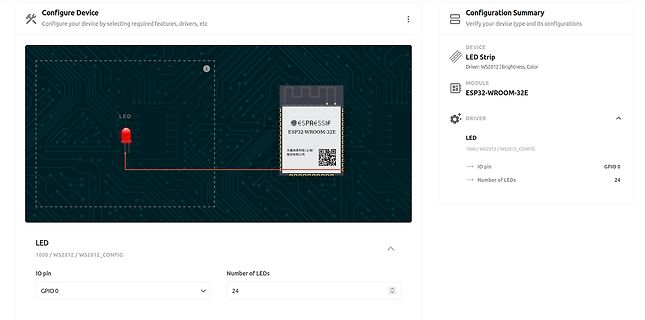
Software-Konfiguration für ESP32-WROOM-32E und LED-Streifen
etc Configuration Summary Verify your device type and its configurations DEVICE LED Strip Driver: WS2812 | Brightness, Color MODULE ESP32-WROOM-32E DRIVER LED 1000 / WS2812 / WS2812_CONFIG IO pin GPIO 0 Number of LEDs 24
in „Neues RTL-SDR-Dongle, Matter-Gerätegenerator von ESP32 und andere Funknachrichten“ · HF, Funk und Felder · · Screenshots
-
Bild
Software-Konfiguration für ESP32 und LED-Strip
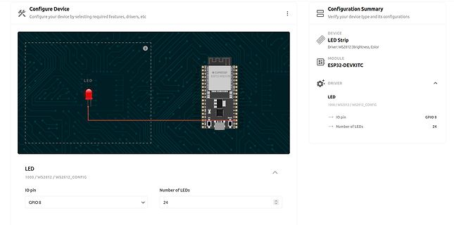
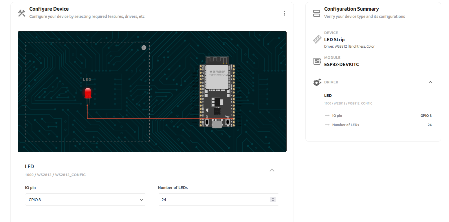
WROOM Configuration Summary Verify your device type and its configurations DEVICE LED Strip Driver: WS2812 | Brightness, Color MODULE ESP32-DEVKITC DRIVER LED 1000 / WS2812 / WS2812_CONFIG IO pin GPIO 8 Number of LEDs 24
in „Neues RTL-SDR-Dongle, Matter-Gerätegenerator von ESP32 und andere Funknachrichten“ · HF, Funk und Felder · · Screenshots
-
Bild
Produktübersicht M5STACK STAMP FLY Drohne
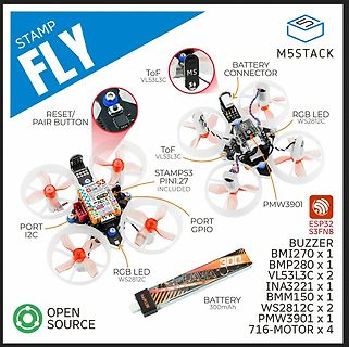
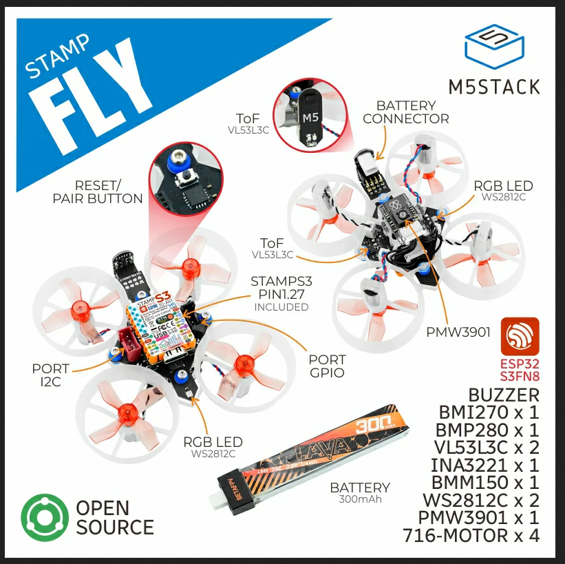
STAMP FLY M5STACK RESET/ PAIR BUTTON ToF VL53L3C BATTERY CONNECTOR RGB LED WS2812C ToF VL53L3C STAMPS3 PIN1.27 INCLUDED PORT I2C PORT GPIO RGB LED WS2812C PMW3901 BATTERY 300mAh ESP32 S3FN8 BUZZER BMI270 x 1 BMP280 x 1 VL53L3C x 2 INA3221 x 1 ISM150 x 1 WS2812C x 2 PMW3901 x 1 716
in „Bauteil-Roundup: Drohnenkit bis Piezoputzanlage“ · Mikrocontroller und Digitale Elektronik · · Sonstiges
-
Bild
Produktübersicht M5Stack STAMP FLY V1.1 Drohne
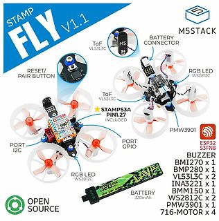
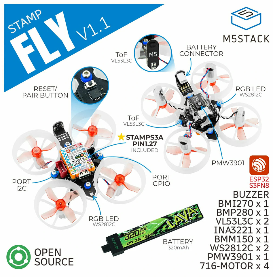
STAMP FLY V1.1 M5STACK RESET/ PAIR BUTTON ToF VL53L3C BATTERY CONNECTOR RGB LED WS2812C ToF VL53L3C STAMPS3A PIN1.27 INCLUDED PORT I2C PORT GPIO RGB LED WS2812C PMW3901 BUZZER BMI270 x 1 BMP280 x 1 VL53L3C x 2 INA3221 x 1 BMM150 x 1 WS2812C x 2 PMW3901 x 1 716-MOTOR x 4 LAVA 320mAh LIHV

in „Neue Bauteile: Hochgeschwindigkeitsfunk, Löttechnik und die Rückkehr der QWERTZ-Tastatur“ · Mikrocontroller und Digitale Elektronik · · Sonstiges
-
Bild
Schaltplan eines LED-Treiberschaltkreises
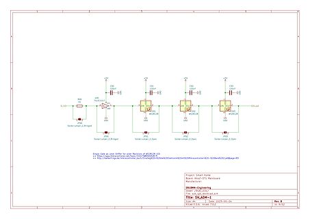
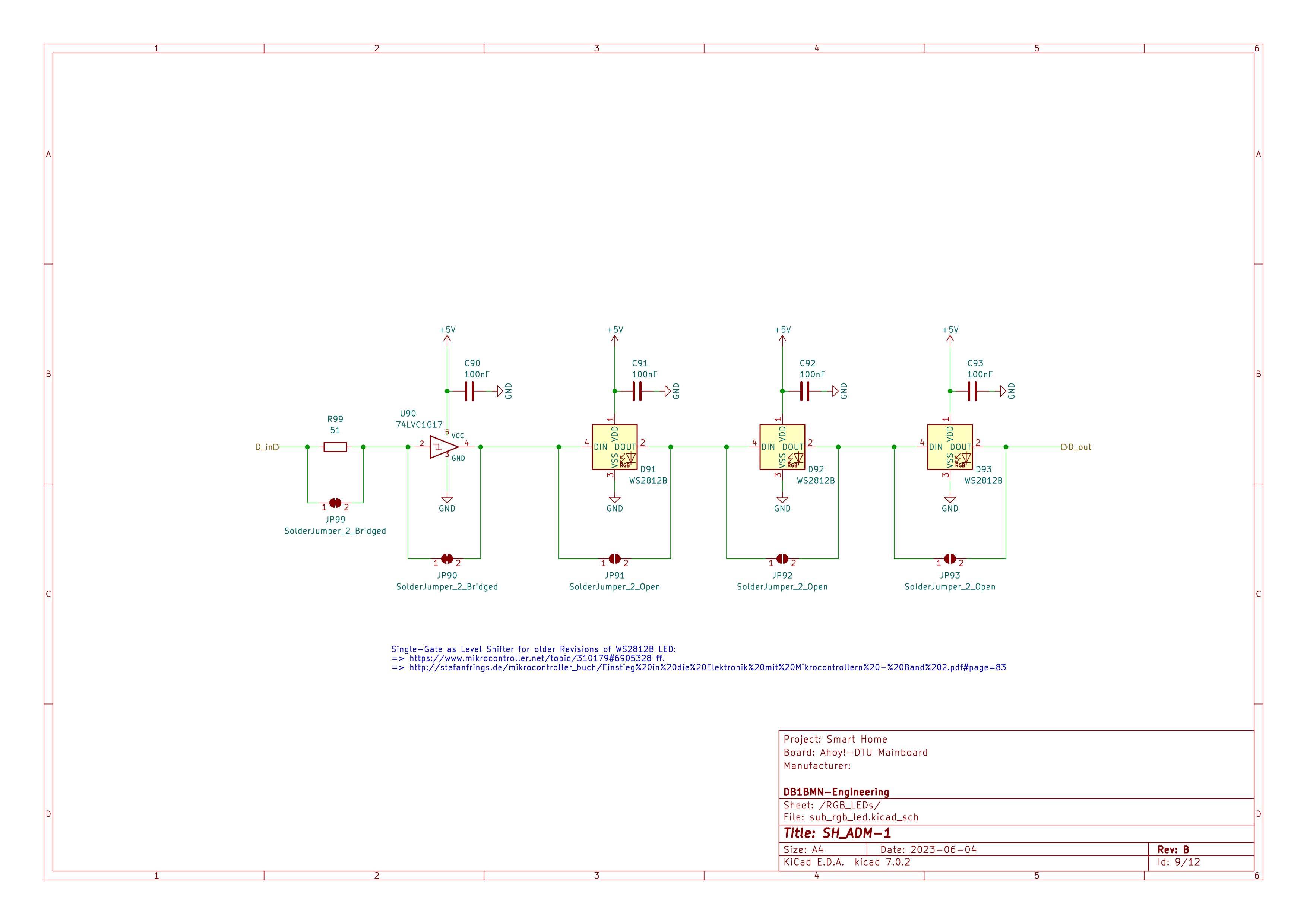
S1, U90 74LVC1G17, D_in, GND, +5V, C90 100nF, JP99 SolderJumper_2_Bridged, JP90, C91 100nF, D91 WS2812B, DIN, DOUT, JP91 SolderJumper_2_Open, GND, C92 100nF, D92 WS2812B, DIN, DOUT, JP92 SolderJumper_2_Open, C93 100nF, D93 WS2812B, DIN, DOUT, D_out, Project: Smart Home, Board: Anydot-DTU Mainboard,
in „Wortuhr Dioden Multiplex entstören“ · Analoge Elektronik und Schaltungstechnik · · Schaltpläne