-
 Bild
Bild
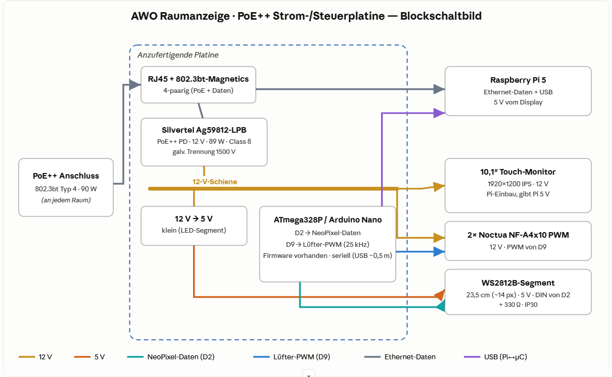
Blockschaltbild einer Strom- und Steuerplatine
Lüfter-PWM (25 kHz) Firmware vorhanden · seriell (USB ~0,5 m) 2x Noctua NF-A4x10 PWM 12 V · PWM von D9 WS2812B-Segment 23,5 cm (~14 px) · 5 V · DIN von D2 + 330 Ω · IP30 12 V 5 V NeoPixel-Daten (D2) Lüfter-PWM (D9) Ethernet-Daten USB (Pi->µC)
in „Projekt AWO-Raumanzeige — Hilfe/Umsetzung einer PoE++ Strom- & Steuerplatine gesucht (Raspberry Pi)“ · Platinen · · Diagramme
-
PDF
Spielfeld-Mini-200.pdf
LED - Spielbrett mit WS2812B 144 LED /m Lageplan der Bauteile 32 33 34 35 36 + + 31 + 7 6 0 3 11 5 3 + 8 + 8 3 12 + 29 2 + 9 + 28 4 + e 7 40 S Zi 4 27 p 3 6 1 l er 2 5 + 1 1 iel r2 Sp 10 2 8 9 6 + 4 3 + + 7 + + 4 5 2 1 25 26
in „Gefräste Platine rationell mit LED 's bestücken“ · Platinen ·
-
Datei
ws2812.h
DMA_HandleTypeDef *DmaHandle); void WS2812_DMA_TransferCompleteHandler(DMA_HandleTypeDef *DmaHandle); #endif /* WS2812B_H_ */
in „WS2812B mit Lib von Martin Hubáček auf F103“ · Mikrocontroller und Digitale Elektronik ·
-
 Bild
Bild
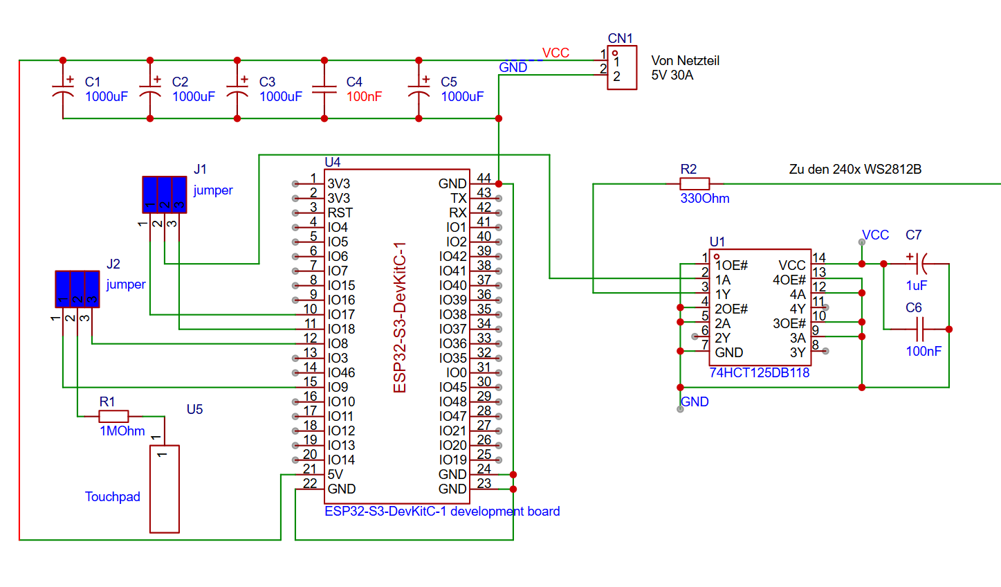
Schaltplan ESP32-S3-DevKitC-1 mit Peripherie
1000uF C3 1000uF C4 100nF C5 1000uF CN1 1 2 VCC GND 5V 30A J1 jumper J2 jumper R2 330Ohm Zu den 240x WS2812B U4 ESP32-S3-DevKitC-1 1 3V3 2 3V3 3 RST 4 IO4 5 IO5 6 IO6 7 IO7 8 IO5 9 IO6 10 IO7 11 IO8 12 IO8 13 IO4 14 IO5 15 IO9 16 IO10 17 IO11 18 IO12 19 IO13 20 IO14 21 5V 22 GND 44 GND 43 TX 42 RX 41 IO
in „ESP32 und 240Stück WS2812B“ · Mikrocontroller und Digitale Elektronik · · Schaltpläne
-
Datei
ws2812_config.h
correctly?" #elif w_lowtime>450 #warning "Light_ws2812: The timing is critical and may only work on WS2812B, not on WS2812(S)." #warning "Please consider a higher clockspeed, if possible" #endif #if w2>0 #define w2_nops w2 #else #define w2_nops 0 #endif #if w3>0 #define w3_nops w3 #else #define w3_nops
in „WS2812b LED-streifen aktualisiert sich erst nach zweitem aufruf“ · Mikrocontroller und Digitale Elektronik ·
-
PDF
WS2812D_Datasheet-English.pdf
the earlier WS2812 LEDS is shown above. As you can see, the timing is virtually identical to the WS2812B timing. This means that the light_ws2812 library is able to support these devices without any modifications. http://www.world-semi.com
in „"Sammelbestellung" für 8mm RGB LEDs mit WS2811 chip“ · Markt ·
-
Datei
KnightRider.ino
/* a LED driver, knight rider style drives a string of intelligent LEDs (WS2812B) speed setting via voltage on analog input */ #include <Adafruit_NeoPixel.h> #define LED_CNT 30 #define LED_PIN 22 #define POTI_PIN A0 Adafruit_NeoPixel pixels(LED_CNT, LED_PIN, NEO_GRB + NEO_KHZ800
in „LED-Lauflicht im Knight Rider Style“ · Projekte & Code ·
-
Datei
ws2812c.asm
------------------------------------------------------------------ ;USING ATTINY1614 @ 5V/20MHz, WS2812B LED STRIP ;FUSE: INT.RC OSC20 ;PORT-Belegung: I/O-A0: UPDI INP-B0: ; INP-A1: INP-B1: ; INP-A2: INP-B2: ; INP-A3: INP-B3: ; OUT-A4: WS2812 DATA ; INP-A5: ; INP-A6: ; INP-A7: .EQU LEDCN = 12*3 ;LED
in „WS2812 control @ ATTiny1614 (Assembler)“ · Projekte & Code ·
-
PDF
Schematic_STM32L05__HSN-TTN_Mini_Node_LoRa_v1.2_2021-02-27.pdf
4 3 3 3 SCL 3 OS GND 8 NEOPIX VCC VEXTOUT D HDR-M-2.54_1x1 4 4 4 SDA R7 GND D 1 10K LED1 GND VCC WS2812B R470 1 4 2 VDD DIN 3 Neopix DOUT VSS GND GND VCC P1 STLINK connector 1 VCC 2 GND 3 SWCLK 4 SWDIO E 5 VCC-T E 6 RSTn C5 C6 100nF 10uF S S D C A L C4 100nF R10 R9 100k 100k JP1 U1 GND PINHD-1X12-CB
-
PDF
Schematic_Atmega_1284p_Mini_Lora_2021-11-18.pdf
TOSC1/PCINT22) 24 PC6 LED1 HDR-M-2.54_1x1 GND PC2 22 PC2(PCINT18/TCK) PC5(TDI/PCINT21)23 PC5 VCC WS2812B-B 1 VEXT PC3(PCINT19/TMS) PC4(TDO/PCINT20) PC4 1 VDD DIN 4 2 DOUT VSS 3 NEO GND J2 HDR-M-2.54_1x4 ARDUINO LED 1 PB1 19-217/BHC-ZL1M2RY/3T PB2 2 PB3 3 PB4 4 LED 1K J1 GND R4 HDR-M-2.54_1x6 D Pullups
in „Hilfe bei Schaltplan 1284p, Mosfet usw, MCU neustart“ · Mikrocontroller und Digitale Elektronik ·
-
Datei
ws2812.S
enable interupts in between bytes only when LEDs can tolerate a longer break in the data signal! ; WS2812B can't!!! (max. 5us in real life, data sheet says 50us!) ;sei subi data_cnt, 1 sbc data_cnt+1, r1 breq ws2812_w_end rjmp ws2812_w_byte_loop ws2812_w_end: pop r26 sts SREG, r26 ; restore I-Bit ret
in „Frage zu IR-Remote+LED-Strips an AVR“ · Mikrocontroller und Digitale Elektronik ·
-
Datei
Liste.txt
Unbekannt 75x 3mm Rot LED 75 Stück unkannt 34x SMD LED Rot Unbekannt 35x Rot Gewinkelt Unbekannt 40x WS2812B RGB Intelligent control LED integrated light source (3,5-5 Volt) 1 Unbekannte Platine 4535670 60341/ Rafi lage 2 540 553634 7 Sekment Anzeigen 24x LTS2301e Unbekannt 10x7 mm ROT 10 Rot 12x17 mm Unbekannt
-
Datei
UhrWS2812.ino
/** * NeoClock * * Clock using 60 WS2812B/Neopixel LEDs and DS3231 RTC * * Libraries needed: * * Adafruit NeoPixel (Library Manager) - Phil Burgess / Paint Your Dragon for Adafruit Industries - LGPL3 * * Rtc by Makuna (Library Manager) -
in „LED Uhr mit RTC braucht Taster“ · Mikrocontroller und Digitale Elektronik ·
-
PDF
Elektronik_Sortimente.pdf
1-2x LED-Streifen: WS2801B (Achtung: Unterschiedliche Anzahl LEDs pro Meter) 1-2x LED-Streifen: WS2812B (Achtung: Unterschiedliche Anzahl LEDs pro Meter) 10x Siebensegment-Anzeige * alle Elemente in Through the Hole und in SMD Bauweise (0805, 0603) Sicherungen Sortiment 5x20mm, flink, 0,16A … 6,3A (
in „Einkaufsliste für die Einrichtung eines Elektronik-Labors“ · Mikrocontroller und Digitale Elektronik ·
-
Datei
riennevaplus.vhd
30 ns Taktperiode für einen 33 MHz Takt constant cCKPERIOD_NS : integer := 30; -- die Zeiten für WS2812B constant cRESET_NS : integer := 50000; constant cT0H_NS : integer := 400; constant cT0L_NS : integer := 850; constant cT1H_NS : integer := 800; constant cT1L_NS : integer := 450; -- die entsprechende
-
Datei
WS2812Ctrl.cpp
--------------------------------------------------------- WS2812Ctrl.c Control of LED Strip with WS2812B driver ----------------------------------------------------------------------- Last committed: $Revision: 05 $ Last changed by: $Author: Thomas.Stief@web.de$ Last changed date: $Date: 04.05.2015 $
-
Datei
main.cpp
classic SuperMini: plain BLUE LED on GPIO8, active-low. * LED_TYPE 1 -> SuperMini Plus/V2: addressable WS2812B NeoPixel on GPIO8. * */ #include <Arduino.h> #include <NimBLEDevice.h> #ifndef LED_TYPE #define LED_TYPE 0 #endif #if LED_TYPE == 1 #include <FastLED.h> #endif // ---------------------------------
-
Datei
ws2812.c
* - clocktime will be 125ns * - port-toggle (sbi) needs 2 cycles - use out instead! * new timing WS2812B: * - LOW: 111 0000000 ( H:0.375us L:0.875us ) * - HIGH: 11111 0000 ( H:0.75us L:0.500us ) * * original (old) timing WS2812: * - LOW: 111 000000 ( H:0.375us L:0.75us ) * - HIGH: 111111 00000 ( H:0.75us
in „AVR ASM ws2811 / ws2812 Ansteuerung mit FastPWM“ · Projekte & Code ·
-
Datei
Liste.txt
---------------------------------------------------- +3x Grün Schaltschrank Warnleuchte 230V 40x WS2812B RGB Intelligent control LED integrated light source (3,5-5 Volt) 1 Unbekannte Platine 4535670 60341/ Rafi lage 2 540 553634 ------------------------------------------------------------------------
-
Datei
main.c
brightness * (width - fwLed) / width); } FastLED.show(); } } int main(void) { init(); FastLED.addLeds<WS2812B, DATA_PIN, GRB>(leds, NUM_LEDS); ledsClear(); Serial.begin(115200); volatile unsigned long data[6]; enum dataIndex { mode, hue, saturation, brightness, duration, width }; data[mode] = 6; data[hue]
in „C++: struct an class übergeben“ · Mikrocontroller und Digitale Elektronik ·
-
Datei
code.c
//setup leds incl. fastled for (int i = 0; i < NUM_LEDS; i++) { strip[i] = 0; } FastLED.addLeds<WS2812B, STRIP_DATA_PIN, GRB>(leds, NUM_LEDS); resetAndBlack(); displayStrip(); // setup dcf DCF.Start(); setSyncInterval(60); //every hour setSyncProvider(getDCFTime); while (timeStatus() == timeNotSet)
in „Arduino hängt sich auf (Wordclock)“ · Mikrocontroller und Digitale Elektronik ·
-
Datei
ws2812.c
WS2812 driver * * Copyright (c) 2014-2018 Frank Meyer - frank(at)fli4l.de * * Timings: * WS2812 WS2812B WS2812S WS2813 Common symmetric(!) values * T0H 200ns-500ns 250ns- 550ns 250ns- 550ns 220ns - 380 ns 470 ns * T1H 550ns-850ns 650ns- 950ns 700ns-1000ns 580ns -1600 ns 800 ns * T0L 650ns-950ns 700ns
in „WS2812B mit Lib von Martin Hubáček auf F103“ · Mikrocontroller und Digitale Elektronik ·
-
Datei
wordclock_esp.txt
= 50; Grün = 50; Blau = 50 => ergibt einen weißen Farbton. //Tipp: Der blaue Anteil muss bei den WS2812B-LED's etwas reduziert werden, da dieser dominanter ausfällt. //Helligkeit der LED's kann mit Werten zwischen 0 - 255 eingestellt werden. //Beispiel 1: Rot = 255; Grün = 255; Blau = 255 => weißer Farbton
in „ESP8266 startet nicht“ · Mikrocontroller und Digitale Elektronik ·
-
PDF
PicoMite_User_Manual.pdf
'type' is a single character specifying the type of chip being driven as follows: O = original WS2812 B = WS2812B S = SK6812 As an example: DIM b%(4)=(RGB(red), Rgb(green), RGB(blue), RGB(Yellow), rgb(cyan)) SETPIN GP5, DOUT BITBANG WS2812 O, GP5, 5, b%() will output the specified colours to an array
in „allgemeine PicoMite Anfängerfragen“ · Mikrocontroller und Digitale Elektronik ·
-
PDF
PicoMite_User_Manual_4_.pdf
'type' is a single character specifying the type of chip being driven as follows: O = original WS2812 B = WS2812B S = SK6812 As an example: DIM b%(4)=(RGB(red), Rgb(green), RGB(blue), RGB(Yellow), rgb(cyan)) SETPIN GP5, DOUT BITBANG WS2812 O, GP5, 5, b%() will output the specified colours to an array
in „Qual der Wahl - Sensoren Auswertung auf Display ("Analog")“ · Mikrocontroller und Digitale Elektronik ·