-
 Bild
Bild
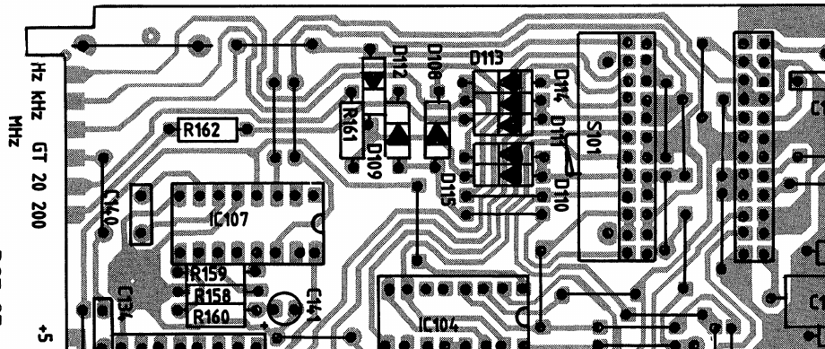
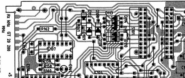
Ausschnitt eines Leiterplatten-Layouts
Hz kHz MHz GT 20 200 C40 IC107 R162 R159 R158 R160 C141 D109 R161 D112 D108 D115 D114 D110 S101 IC104 +5
-
 Bild
Bild
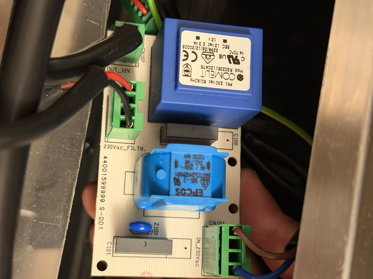
Leiterplatte mit Transformator und Bauteilen
COMELIT Mod. R3023E120A75 PRI. 230 VAC 50/60HZ SEC. 12 VAC 2.3 VA 2298/26/12/20005 tc 70°C CE US 230Vac_FILTR. 44001599999 S-DD1 C101 Z100 C100 IN_230VAC
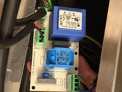
-
 Bild
Bild
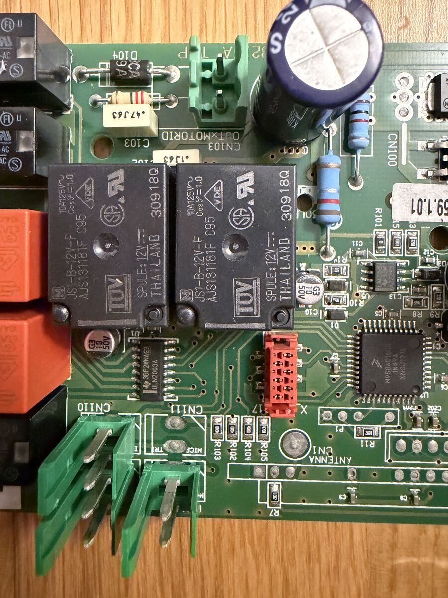
Bestückte grüne Leiterplatte mit Transformatoren
D104, 9A, C103, CN103, 30918Q, 104125V, Cos=1.0, JS1-B-12V-F, AJS131181F, C95, TOV, SPULE: 12V, THAILAND, CN100, R101, 59.1.01, R10, C13, R10, R8, R9, R3, IC10, R11, CN11, CN10, R109, R102, R104, R105, UN1, R7
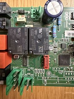
-
 Bild
Bild
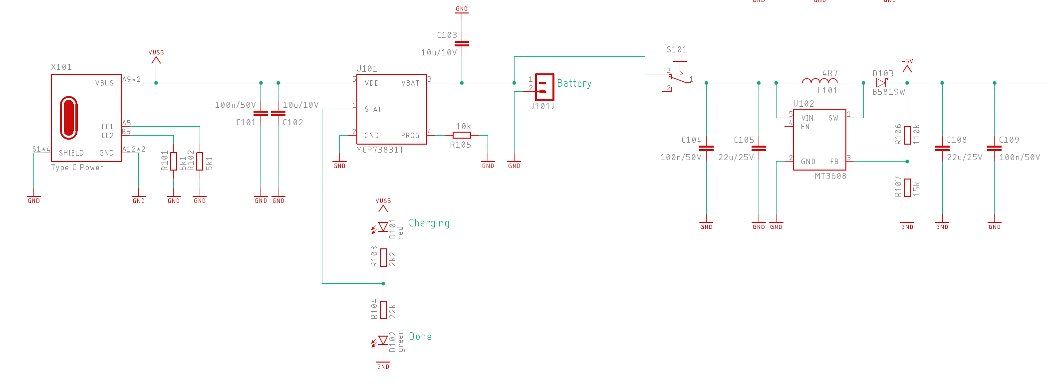
Schaltplan einer Akku-Ladeschaltung mit USB-C
X101 VBUS A9*2 CC1 CC2 GND A12*2 SHIELD Type C Power R101 10R GND R102 5k1 GND C101 100n/50V GND C102 10u/10V GND U101 VDD VBAT STAT PROG GND MCP73831T R105 10k GND GND C103 10u/10V S101 GND L101 4R7 D103
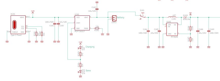
-
 Bild
Bild
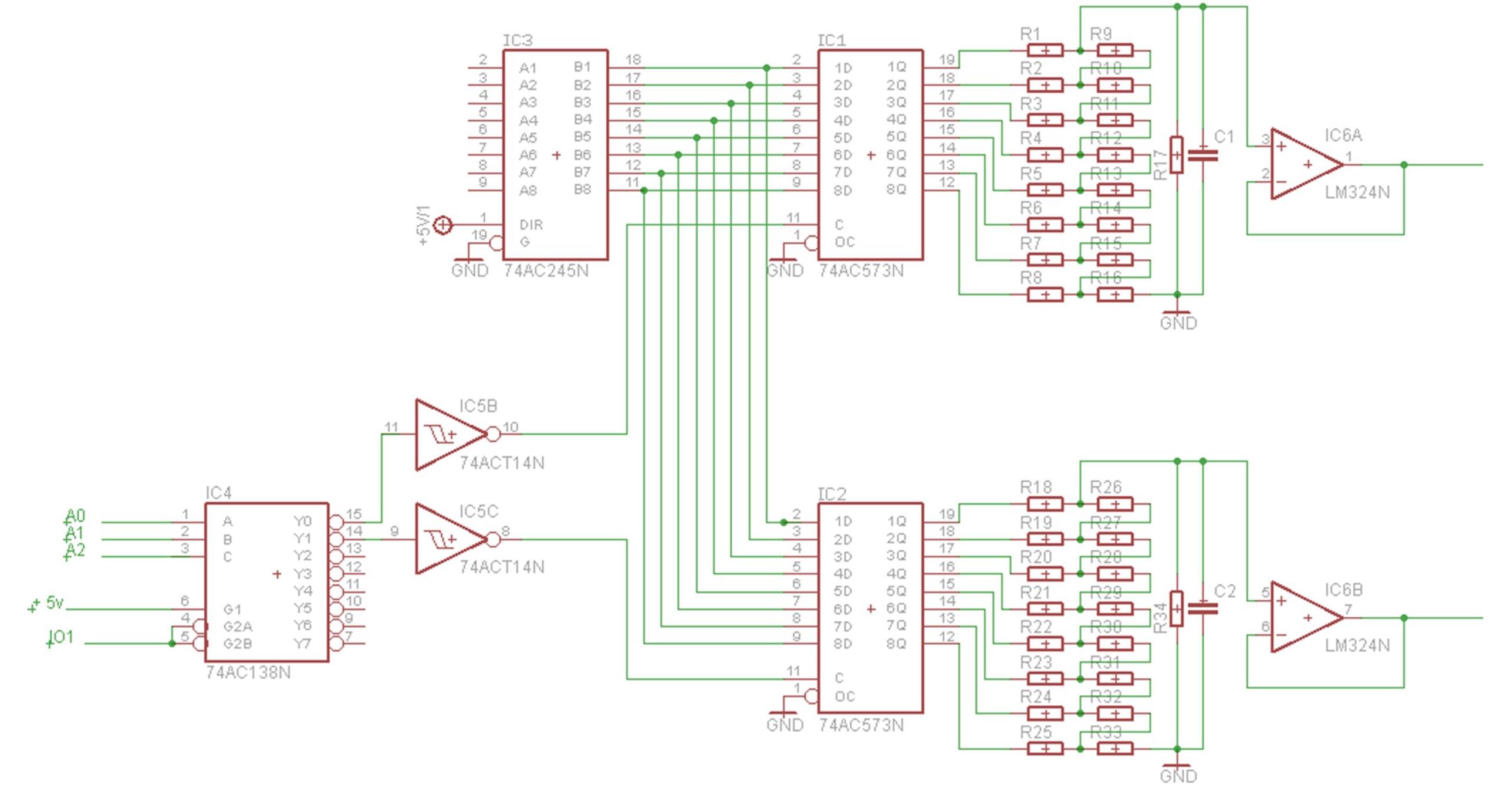
Schaltplan mit Logikgattern und Operationsverstärkern
IC3 2 A1 B1 18 IC1 1D 1Q 19 R1 R9 2 A2 B2 17 2D 2Q 18 R2 R10 3 A3 B3 16 3D 3Q 16 R3 C1 4 A4 B4 15 4D 4Q 15 R5 5 A5 B5 14 5D 5Q 14 R6 6 A6 B6 13 6D 6Q 13 R14 7 A7 B7 12 7D 7Q 12 R15 8 A8 B8 11 8D 8Q 11 R16 9 DIR GND 74AC245N 19 +5V/1 11 C 1 GND OC 74AC573N R7 R8 R14 R15 R16 GND IC5B 11 + IC4 A0 A1 A2 1 A 2 B 3 C 12 Y3 13 Y4 14 Y5 15 Y0 16 Y6 10 6 G1 7 5V 101 G2A G2B 74AC138N IC5C 9 + IC2 2 1D 1Q 19 R18 R26 3 2D 2Q 18 R19 R20 4 3D 3Q 16 R20 R38 5 4D 4Q 15 R22 R30 6 5D 5Q 14 R23 R32 7 6D 6Q
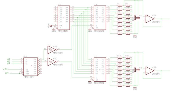
-
 Bild
Bild
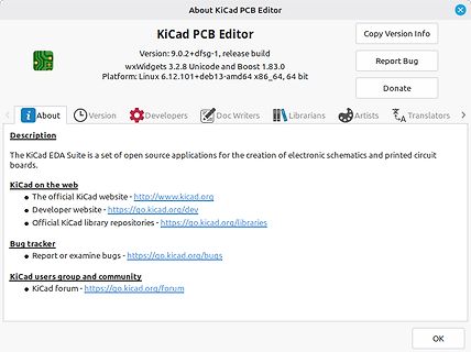
About-Dialog des KiCad PCB Editors
Version: 9.0.2+dfsg-1, release build wxWidgets 3.2.8 Unicode and Boost 1.83.0 Platform: Linux 6.12.101+deb13-amd64 x86_64, 64 bit Copy Version Info Report Bug Donate About Version Developers Doc Writers Librarians Artists Translators Description The KiCad EDA Suite is a set of open source applications
-
 Bild
Bild
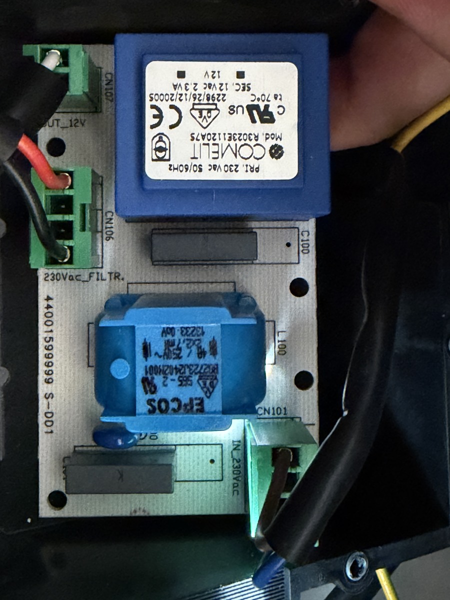
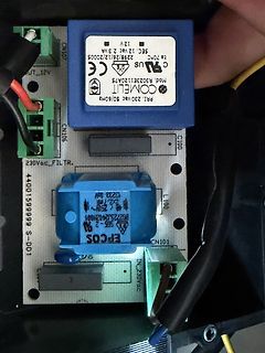
Bestückte Leiterplatte mit Transformator und Netzteilmodul
CN107 12 V SEC, 12 VAC 2.3 VA 229/26/12/20005 UL CE Mod. R3023E1120A75 COMELIT PRI. 230 VAC 50/60HZ CN106 C100 230VAC_FILTR. 44001599999 S-DD1 EPCOS L100 CN101 IN 230VAC
-
 Bild
Bild
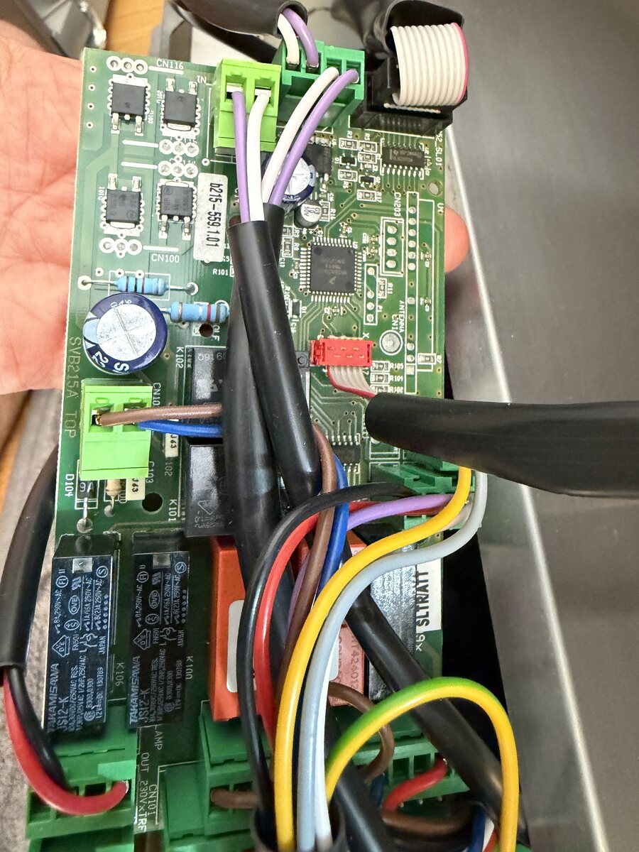
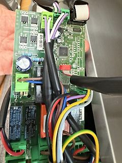
Elektronikplatine mit Kabeln und Relais
CN116, CN100, SV6215A TOP, D10, K102, K101, K104, K105, TAKAMISAWA, 250V~ 5A, 100V~ 10A, 230V~ 5A, 230V~ 10A, OUT 230V~ 1X, B215-558.101
-
Thread
Sirius Dunstabzug – Glaslift fährt kurz hoch und sofort wieder runter
öffnen werde für Details) - Hersteller: CIAR - Typ: LM25_N - Eingang: 24–30 V DC - Strom: 2,5 A max. - Duty Cycle: 2 min ON / 5 min OFF - Max. Load: 400 N Motor/Bauteil ist dieser: https://ciar.it/catalog/en/linear-actuators/85-lm25-n.html
ausgebaut aus dem Motor. Ging relativ leicht und steckte nur drinnen. (Siehe Fotos) Aufschrift: S566A 319
-
Thread
[V] Konvolut (83) SMD Leistungsinduktivitäten, Würth, Fastron, Coilcraft (35€)
://www.mouser.de/de/ProductDetail/Wurth-Elektronik/744043003?qs=PGXP4M47uW5A9aPDpHYFLQ%3D%3D 4x Fastron Leistungsdrossel, SMD, 100 µH, 1.9 A, PISR-101M-04 https://www.buerklin.com/de/p/fastron/festinduktivitaeten/pisr-101m-04/74D4824/ 4x Fastron Leistungsdrossel, SMD, 220 µH, 1.1 A, PISN-221M-04 https://www.buerklin.com/de/p/fastron/festinduktivitaeten/pisn-221m-04/74D4766/ 12x Würth 7447709101 Leistungsinduktivitäten – SMD WE-PD 100uH 2.5A DCR=110mOhms AEC-Q200 https://
-
 Bild
Bild
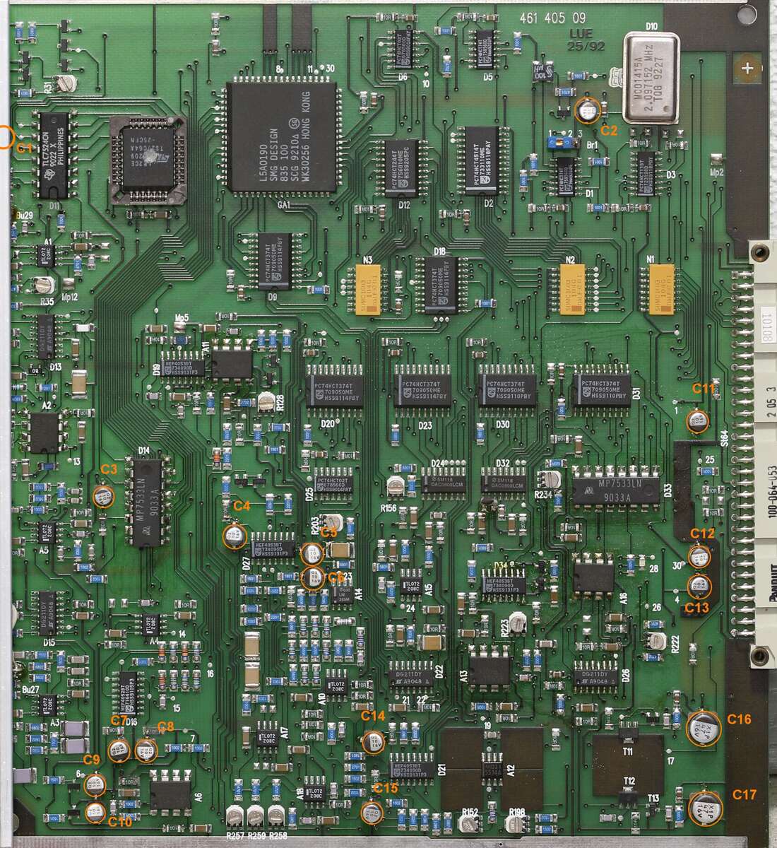
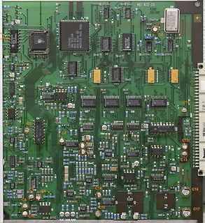
Detailaufnahme einer bestückten Leiterplatte
461 405 09 LUE 25/92 MCO1438A 2-100 9267 LS401890 835 100 GN SC9 9210 0 W3226 NING KONG GA1 D1 D12 D2 D3 D5 D10 D13 D14 D15 D16 D18 D19 D20 D23 D24 D30 D32 D33 D35 D56 D60 D61 D62 D63 D64 D65 D66 D67 D68 D69 D70 D71 D72 D73 D74 D75
-
Thread
KiCAD Problem, hat sich von selbst deinstaliert
Überraschungen wichtiger. > Ich brauche zum Arbeiten nicht die neuesten Programmversionen. Da bin ich zu 101% bei dir. Aber da schliesst sich natuerlich gerade im Zusammenhang mit Kicad wieder der Kreis, wie ich oben ja schon beschrieben habe. Und wenn du jetzt nicht nur mit Linux spielst sondern es dein
und natürlich Debian. Wer damit zurecht kommt, hat dann auch die Erfahrung und die Kenntnisse, um a) eine qualifizierte Entscheidung für einen Exoten zu treffen, und dann b) auch damit vernünftig zurande zu kommen. Eigentlich simpel, man setzt ja auch keine Fahranfänger in Formel1-Renner oder in Doppelstöcker
-
Thread
Suche IC SN74141 in Dil 10 Stk.
Ist schon fertig https://www.dk.freelancer.com/u/ysjoelfir/portfolio/74141e-a-simple-replacement-for-an-old-ic-7104594# Transistoren wohl MMBTA42
Zehnerstellen hat man ja extra Ausgänge. https://download.mikroe.com/documents/datasheets/TPIC6A595_datasheet.pdf
-
Thread
Balkonkraftwerk, Basiswissen und Aufbau.
runterregeln lassen, dann "verbrennt" die Leistung in den Modulen - für Warmwasseraufbereitung o.ä. nutzen
Martin S. schrieb im Beitrag #8083517: > Cekon. Ist für 3x16A Dauerstrom spezifiziert. Bis 3x125A...
-
Thread
Polwechselnden Impuls mit Transistoren verstärken
ist es üblich, solche qualitativen Angaben wie "möglichst gering" mit Quantitäten wie "höchstens 20 mA" zu fixieren. Wenn du also 20 mA fließen lassen könntest, dann vergiss die Transistoren und puffere das Signal nur mit "low coil power" bzw "high sensitive" Relais wie z.B. Finder 40.62.7.024.0000 (20mA) oder Hongfa HFD16 (10mA)
-
 Bild
Bild
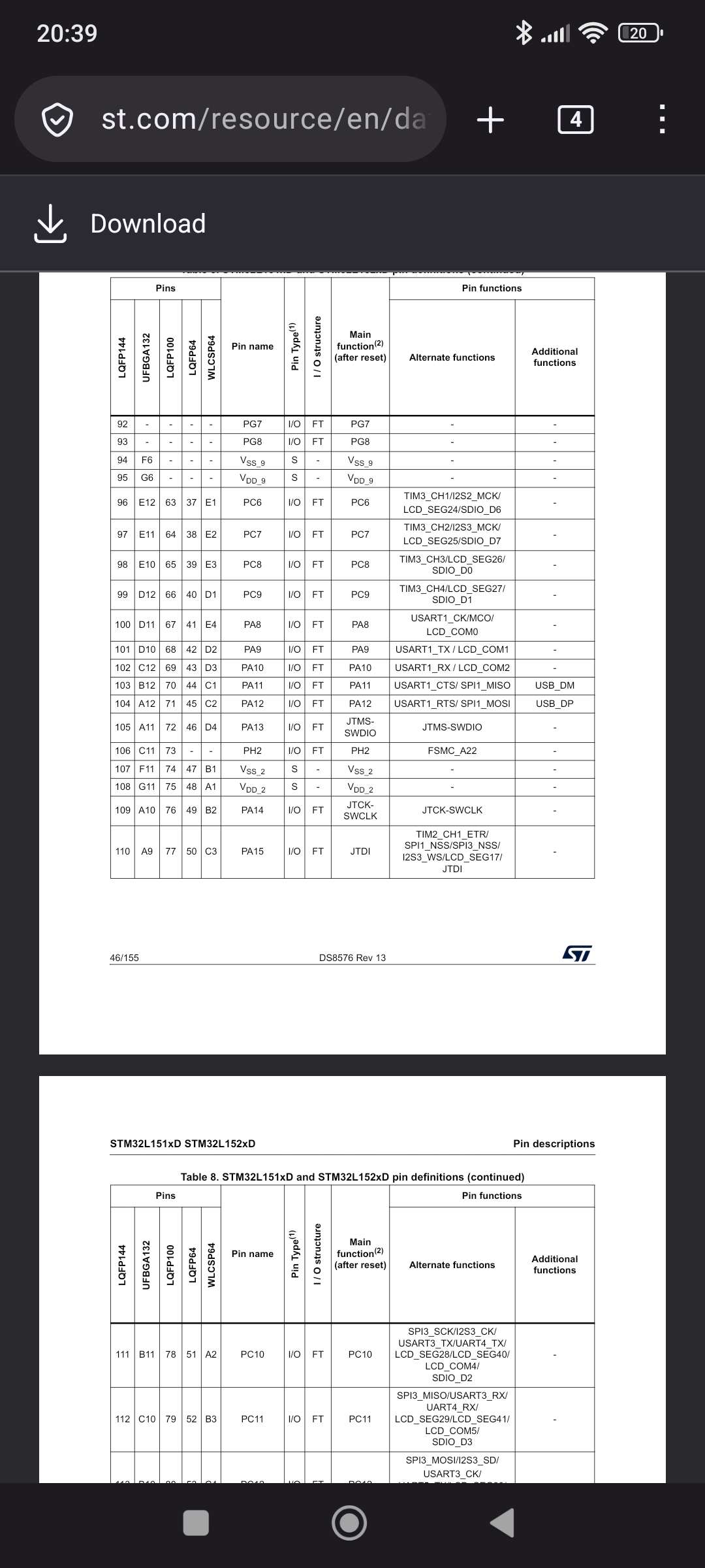
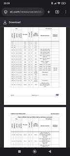
Pinbelegungs-Tabelle eines STM32L151x/STM32L152xD Mikrocontrollers
PA8 I/O FT PC8 98 E10 65 39 E3 I/O FT PC9 99 D12 66 40 D1 I/O FT PC9 100 D11 67 41 E4 PA8 I/O FT PC9 101 D10 68 42 D2 I/O FT PC10 102 C12 69 43 D2 I/O FT PC10 103 B12 70 44 C1 PA10 I/O FT PC10 104 A12 71 45 C2 I/O FT PC11 105 A11 72 46 D3 I/O FT PC11 106 C11 73 ... STM32L151xD STM32L152xD Pin definitions
-
 Bild
Bild
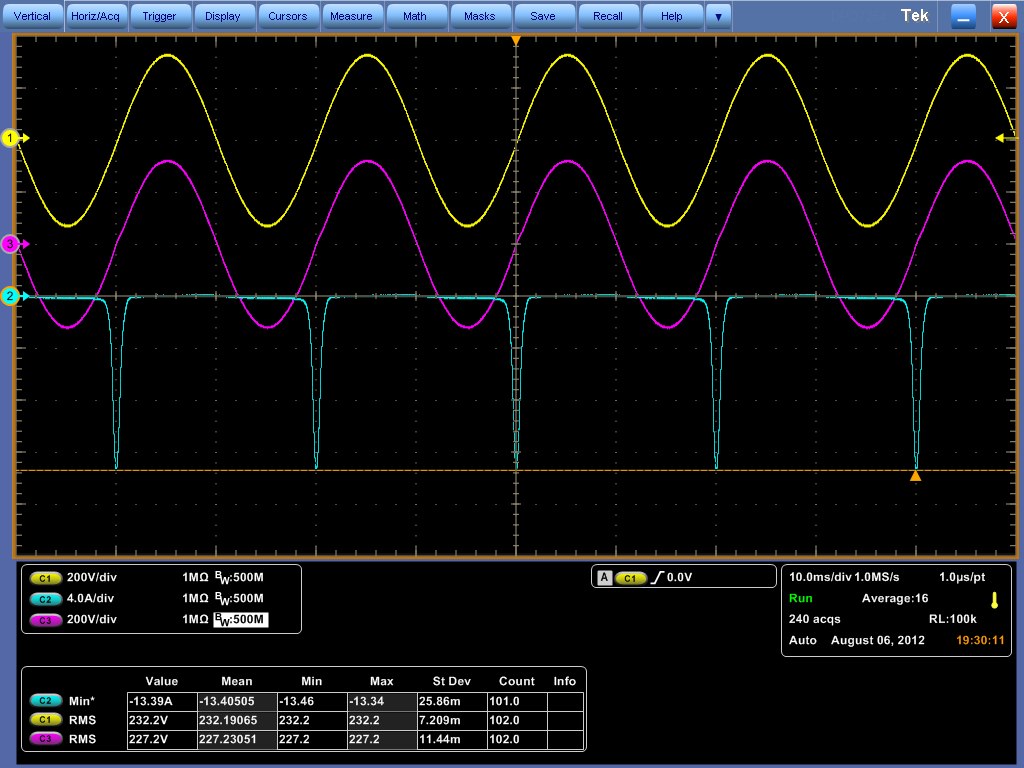
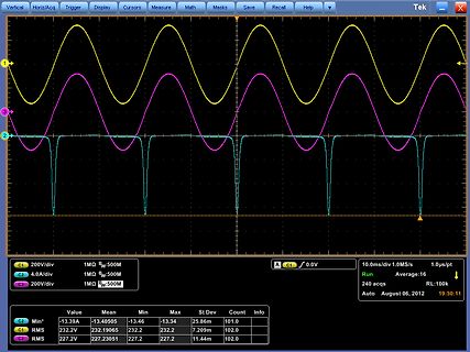
Oszilloskop-Messung von drei Signalen
Trigger Display Cursors Measure Math Masks Save Recall Help Tek X 1 2 3 C1 200V/div 1MΩ BW:500M C2 4.0A/div 1MΩ BW:500M C3 200V/div 1MΩ BW:500M A C1 0.0V Run 10.0ms/div 1.0MS/s 1.0µs/pt 240 acqs RL:100k Auto August 06, 2012 19:30:11 C3 Min* -13.39A -13.40505 -13.46 -13.34 25.86m 101.0 C1 RMS 232.2V 232.19065
-
Thread
Multimeter will keine Kapazitäten messen
script geschrieben, an einem Kopfhörerausgang kann man ein passendes Signalsample abspielen (Kammerton A ist beliebt, 440 Hz), das V-Sync-signal am VGA hat je nach Framerate 50 ... 72 Hz oder so, das Hsync-signal ist im zweistelligen kHZ Bereich, ...
Bei einigen alten 200ern immer so 50 Ohm zu wenig, bei einem neuen (habe gerade nur den einen) aber 101 bei Sollwert 100. Bei diversen alten Anderen aber totalen Mist, entweder sind die "hochohmiger" geworden, oder die haben einen anderen 3-Ring-Code als der Rest und ich kenne ihn nicht. Will sagen: 100%
-
Thread
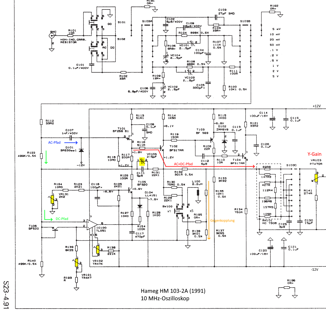
Schaltungstechnik Oszilloskop-Y-Eingangsverstärker (Hameg)
Um was geht es denn genau? Ich war an der Entwicklung u. a. von HM 1007, 205-3 und 303 beteiligt.
also um den Faktor 18 geringer als in der AN47. Den 2. OP-Amp A2 mit Verstärkungsfaktor 10 hat sich Hameg gespart. Bisher ist das nur eine Aufzählung der Gemeinsamkeiten und Unterschiede, die Funktionen muß ich erst noch richtig verstehen...
-
 Bild
Bild
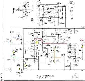
Schaltplan eines 10 MHz Oszilloskops
S101, S102, S103A, S103B, R101, R102, R103, R104, R105, R106, R107, R108, R109, R110, R111, R112, R113, R114, R115, R116, R117, R118, R119, R120, R121, R122, R123, R124, R125, R126, R127, R128, R129, R130, R131, R132, R133, R134, R135, R136, R137, R138, R139, R140, R141, C101 bis C126, T101 bis T106, D101 bis D104, VR101 bis VR104, Hameg HM 103-2A (1991) 10 MHz-Oszilloskop, +12V, -12V, AC-Pfad, DC-Pfad, Y-Gain
-
 Bild
Bild
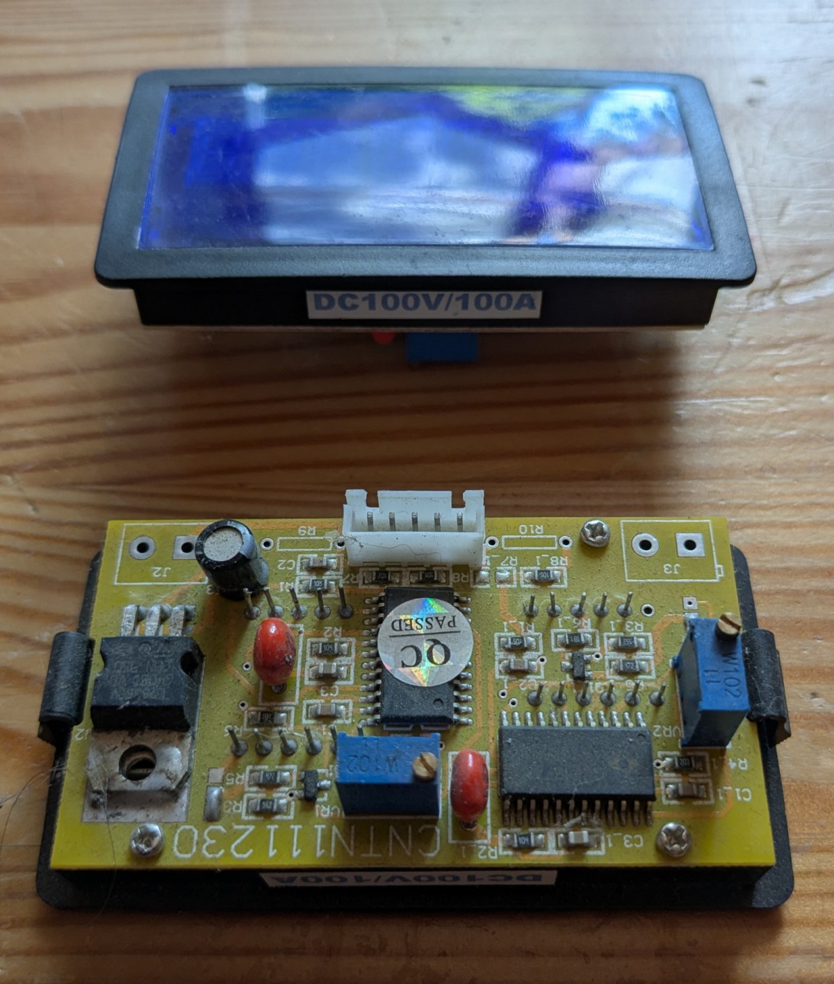
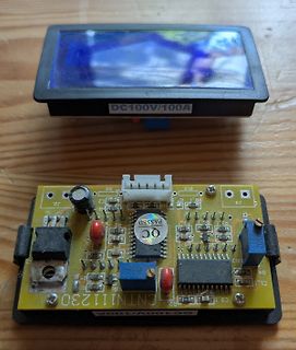
DC-Voltmeter-Modul mit Display und Leiterplatte
DC100V/100A CNTN111230 J2 C2 R2 R9 R10 J3 QB PASSED QC J1 101 VR2 CL1 C3 R5 R3 R1
-
Thread
KI, der stochastische Papagei
five new elements after the given ones. So answer: 37, 50, 65, 82, 101. We can also mention that it's an arithmetic progression of differences (second-order). Provide maybe a short explanation. The user didn't ask for explanation but could be helpful. Provide in
www.spiegel.de/netzwelt/studie-ki-modell-claude-zitiert-russisches-desinformations-netz-als-nachrichtenquelle-a-ff43dfdb-2f49-4311-8aea-f77a58192959
-
Artikel
AVR Arithmetik
Some Useful Assembler Multibyte Maths Subroutines & Macrocalls (oder hier) Elm-Chan's Bibliotheken u.a. Arithmetik Multiplication by a Fixed Point Constant, Embedded.com, 06/16/09 M. Rosenblattl, A. Wolf: Fixed Point Library According to ISO/IEC Standard DTR 18037 for Atmel AVR Processors (pdf, engl., 133 S.) ISO/IEC DTR 18037 (pdf, engl., 101 S.) – Spezifikation einer Erweiterung von C99 zur Unterstützung von Embedded Systems A Different Kind of Multiplication
-
 Bild
Bild
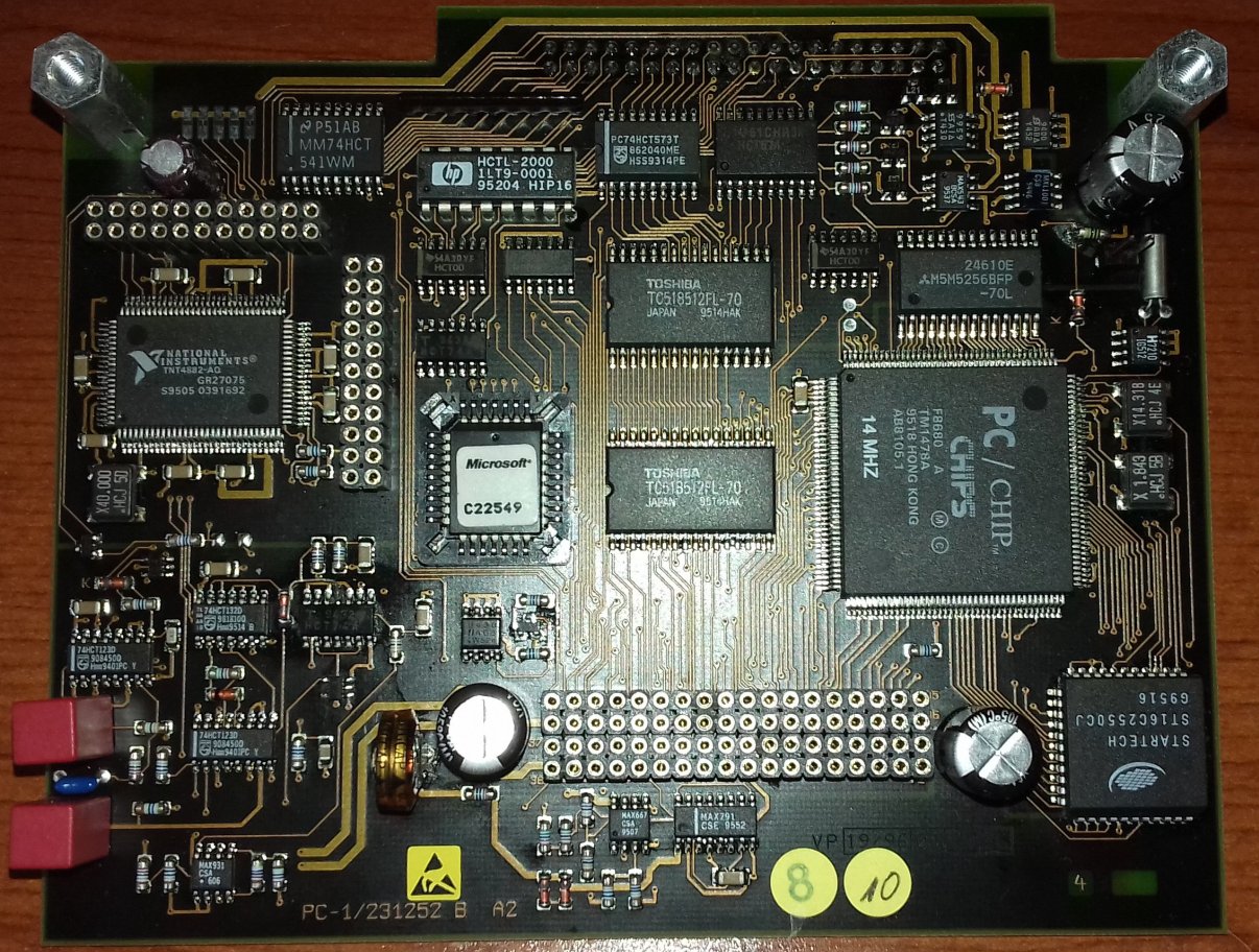
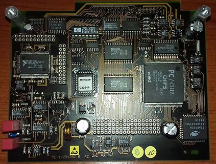
Bestückte Leiterplatte einer Computerkomponente
0001 95204 HIP16 HCT1-2000 TOSHIBA TOS18512L-70 JAPAN 9514MA MICROSOFT C22549 CHIPS PC/CHIP 14 MHZ AB101-5 1998 AB1518 HONG KONG 24610E MS8256BFP 70L X1-318 JKF AE 9916 STARCH 69516 ST1C2550CJ PC-1/231252 B A2
-
 Bild
Bild
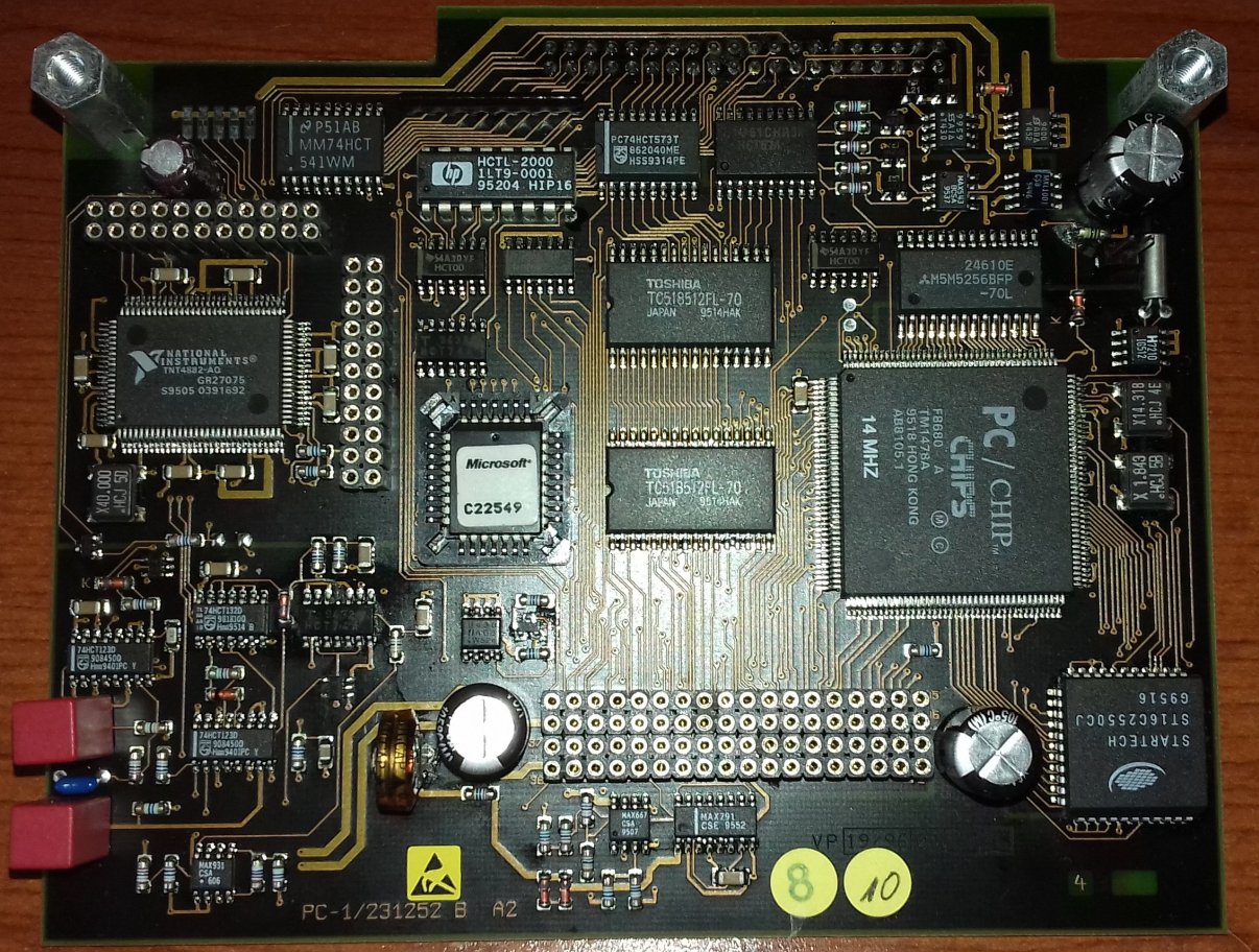
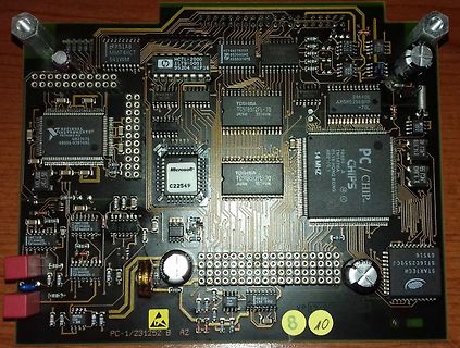
Bestückte Leiterplatte einer Computerkomponente
0001 95204 HIP16 HCT1-2006 TOSHIBA TOS18512L-70 JAPAN 9514MA MICROSOFT C22549 CHIPS PC/CHIP 14 MHZ AB101-5 1998 AB1518 HONG KONG 24610E MS8256BFP 70L X1-318 JKF AE 9916 STARCH 69516 ST1C2550CJ PC-1/231252 B A2
-
Artikel
Drehgeber
unter realen Bedingungen zeigen jedoch schnell die Schwächen dieser Ansätze. Flankenerkennung von A und Pegelauswertung von B. Viele Sparvarianten verwenden einen externen Interrupt, welcher auf die steigende oder fallende Flanke von Spur A auslöst und dann den Pegel von B auswertet. Ist B=0, dann
zwei Schwachstellen. Die Auflösung wird auf ein Viertel reduziert, weil nur jede steigende Flanke von A ausgewertet wird. Pendelt der Encoder zwischen zwei Codes, bei denen A seinen Pegel wechselt, kommt es zu (sehr) vielen Interrupts, die den Mikrocontroller vollkommen auslasten können. interpretiert
-
Thread
Warum funktioniert eine ISDN-Dose nicht als Netzwerkdose?
Umbelegen auf Ethernet nur eine der Buchsen genutzt werden, die andere sollte durch einen Blindstecker o.ä. blockiert werden. [pre] Nr. ISDN Ethernet (100BaseT) 1 - Tx+ 2 - Tx- 3 a2 Rx+ 4 a1 - 5 b1 - 6 b2 Rx- 7 - - 8 - -
nichts. Das mit den Fragezeichen ist ein reines > Stilmittel. "multiple exclamation marks are a sure sign of a diseased mind" - und das lässt sich auf Fragezeichen erweitern. Gut, haben wir das geklärt. Du bist halt damit überfordert, eBay-Links zu posten, und Du bist damit überfordert, in