-
PDF
P14067EJ2V0DS00.pdf
0 10 20 30 0 4 1 2 4 6 8 10 14 20 30 Drain CurrentD(mA) Frequency f (GHz) 4 Data Sheet P14067EJ2V0DS00 NE3210S01 S-PARAMETERS MAG. AND ANG. V DS= 2 V, I = 10 mA FREQUENCY S 11 S21 S12 S22 MHz MAG. ANG. MAG. ANG. MAG. ANG. MAG. ANG. 2000.0000 0.973 –21.2 4.450 154.2 0.022 75.9 0.550 –15.2 2500.0000 0.951
in „Vorverstärker für magnetische Loop“ · HF, Funk und Felder ·
-
PDF
User_Guide_ETEMB043013XDHAL_Interface_Description_V1.0.pdf
IC and associated components if not used. Interface Description V1.0 2020-03-13 page 10 of 17 2.5 RS232 -CN5 Pin # Name I/O Description 1 VSS P GND 2 RTS O RS232 Request To Send 3 TX O RS232 TXD 4 RX I RS2132 RXD 5 CTS O RS232 Clear To Send 6 VSS P GND RTS: PD4 TX: PD5 RX: PD6 CTS: PD3 FORCE_ON: PJ12,
in „EDT Display Interface mit STM32F7“ · Mikrocontroller und Digitale Elektronik ·
-
Datei
2013.03.25_Testboard.bas
----------- ------------------------------------------- Serielle Schnittstellen & Autoflash über RS232 & RS232 Variablen Config Com1 = 57600 , Synchrone = 0 , Parity = None , Stopbits = 1 , Databits = 8 , Clockpol = 0 ' RS232 über USB Enable Urxc On Urxc Com1_isr Dim Rs232_flash As Byte , Rs232_str As
in „siemens tc35i und rs232 Kommunikationsprobleme“ · Mikrocontroller und Digitale Elektronik ·
-
PDF
ACB_Datasheet_premininary.pdf
Data sheet AKKON USB Contrtoller Board DS001 AKKON USB CONTROLLER BOARD Development board with the PIC18F4550™* Datasheet 16bit Microcontroller board with USB Authors: Gerhard Burger Version: 1.0 Last update: 19.10.2005 File: Attachments: no
in „interessiert an einem PIC18 USB controller board?“ · Markt ·
-
PDF
ACB_Datasheet_premininary.pdf
Data sheet AKKON USB Contrtoller Board DS001 AKKON USB CONTROLLER BOARD Development board with the PIC18F4550™* Datasheet 8bit Microcontroller board with USB Authors: Gerhard Burger Version: 1.0 Last update: 19.10.2005 File: Attachments: no
in „interessiert an einem PIC18 USB controller board?“ · Markt ·
-
Datei
Descriptions.txt
symbol 66 Positive VOLTAGE REGULATOR 65 P-Channel Enhancement MOSFET (HEXFET); -100V; -12A; 0,3Ohm 62 RS232 TRANSEIVER 61 OMRON SWITCH 58 TEST PIN 54 SMD PAD 50 Resistor 45 SOLDER PAD drill 1.0 mm, distributor Buerklin, 12H555 44 Z DIODE 43 WAGO SREW CLAMP 42 SOLDER PAD RTM, drill 1,1mm, distributor Buerklin
in „[KiCad] Bibliotheksaufbau - Konzeptideen gesucht“ · Platinen ·
-
Datei
ds1820.asm
relativ lange wandlungszeit erheblich kürzen (leichte änderung in main-routine) ; - optional einem rs232-treiber-baustein (z.b. max232cpe o.ä.) um bei nutzung des rs232- ; ausganges des avr den pegel auf normgerechte spannungen umzusetzen, die rs232-schnitt- ; stelle fungiert im programm nur als sender
in „mehere ds1820 an einem bus“ · Mikrocontroller und Digitale Elektronik ·
-
PDF
EPOS2_Communication_Guide_En.pdf
interface. Even other CANopen devices (I/O modules) supporting the CANopen standard CiA DS 301 may be accessed. Figure 7-32 Gateway Communication – Structure Communication data are exchanged between USB/RS232 master and the gateway using a maxon-spe- cific USB/RS232 protocol. Data between
in „CRC Funktion übersetzen (so das diese auf GCC läuft)“ · Mikrocontroller und Digitale Elektronik ·
-
PDF
uC51_UEdit_T_Deck_s.pdf
Command Line Arguments = Category&02 = COMPILER OPTIONS Processor = Intel MCS51 (8051-family)|Dallas DS80C390|Dallas DS80C400|Freescale/Motorola HC08|Zilog Z80|GameBoy Z80|Atmel AVR|Microchip PIC 14- bit (p16f84-family)|Microchip PIC 16-bit (p18f452-family)|Toshiba TLCS-900H|Phillips XA51 Compiler Options
in „Wickenhäuser uC51 und UltraEdit“ · Mikrocontroller und Digitale Elektronik ·
-
PDF
DS_FT232R_v104.pdf
™ Future Technology Devices International Ltd. FT232R USB UART I.C. Incorporating Clock Generator Output and FTDIChip-ID™ Security Dongle The FT232R is the latest device to be added to FTDI’s range of USB UART interface Integrated Circuit Devices. The FT232R is a USB to serial UART interface with optional clock generator output, and the new FTDIChip-ID™ security dongle feature. In addition, asynchronous and synchronous bit bang interface modes are available. USB to serial designs using the FT232R have been further simplified by fully integrating the external EEPROM, clock circuit and USB resistors onto
in „Mosfet für FT232R“ · Analoge Elektronik und Schaltungstechnik ·
-
PDF
DS_FT232R_v104.pdf
™ Future Technology Devices International Ltd. FT232R USB UART I.C. Incorporating Clock Generator Output and FTDIChip-ID™ Security Dongle The FT232R is the latest device to be added to FTDI’s range of USB UART interface Integrated Circuit Devices. The FT232R is a USB to serial UART interface with optional clock generator output, and the new FTDIChip-ID™ security dongle feature. In addition, asynchronous and synchronous bit bang interface modes are available. USB to serial designs using the FT232R have been further simplified by fully integrating the external EEPROM, clock circuit and USB resistors onto
in „FT232R Frage Bezug auf Masse“ · Mikrocontroller und Digitale Elektronik ·
-
PDF
DS_FT232R_v102.pdf
™ Future Technology Devices International Ltd. FT232R USB UART I.C. Incorporating Clock Generator Output and FTDIChip-ID™ Security Dongle The FT232R is the latest device to be added to FTDI’s range of USB UART interface Integrated Circuit Devices. The FT232R is a USB to serial UART interface with optional clock generator output, and the new FTDIChip-ID™ security dongle feature. In addition, asynchronous and synchronous bit bang interface modes are available. USB to serial designs using the FT232R have been further simplified by fully integrating the external EEPROM, clock circuit and USB resistors onto
-
PDF
DS18S20_RS232.pdf
T2OUT T2IN 12 1 D111 3 Eingang R1IN R1OUT Ausgang 1 GND PL101-3 TXD Eingang8 R2IN R2OUT 9 9 1N4148 DS18S20 GND PL101-7 RTS MAX232 B GND B PL101-9 RI PL101-10 +5V X101 1 B 2 S 3 U 4 GND PN61729-S C C +5V 1C V IC101P C105 D 5G X7R-G1206 10/16 1 D D M. Pabelick GND 1 2 3 4 5 6
in „Temperaturmessung DS18S20 mit MAX232 über Serielle Schnittstelle“ · Mikrocontroller und Digitale Elektronik ·
-
PDF
TB6560schv1.2.pdf
X1 R 11 T1IN T1OUT 14 10 T2IN T2OUT 7 1 2 12 R1OUT R1IN 13 2 6 B 9 R2OUT R2IN 8 3 7 +5V T 4 8 T MAX232 5 9 C E 2 + C16 C12 O F GND +C14 C11 R 47µ 1µ _ 10µ 1µ O 1 2 M 0 9 7 8 +12V 2 1 1 8 1 GND GND T 3 CLK D C M M M 6 6 6 6 V T V V 1 1B 1B B B 21 O D DS DS DS S DIR P MOTOR2_A 4 16 1 ENBL OUT-AP 2 MOTOR2
in „Schrittmotorsteuerung TB6560 - Motor spinnt“ · Mikrocontroller und Digitale Elektronik ·
-
Datei
PIC16F630_DS1820.asm
& erkennen call delay_600us movlw 0xCC movwf ds1820 call write_ds1820 ; ROM-Kommando 0xCC: Skip ROM call delay_600us movlw 0x44 movwf ds1820 call write_ds1820 ; Kommando 0x44: Convert Temperature call delay_1s call init_ds1820 call delay_600us movlw 0xCC movwf ds1820 call write_ds1820 ; ROM-Kommando 0xCC: Skip ROM movlw 0xBE movwf ds1820 call write_ds1820 ; Kommando 0xBE: Read Scratchpad call read_ds1820 movf ds1820, w movwf temp1 ; Temperatur LSB call read_ds1820
in „DS1820 an PIC16F630 - Softwareprobleme, ich verzweifle!“ · Mikrocontroller und Digitale Elektronik ·
-
PDF
XPort_reference_design_and_guidelines.pdf
then you will need a back door circuit to provide a logic OR between the host microprocessor and an RS232 transceiver. The following is a block diagram of the circuit to implement a back door serial channel. See the XPort reference design (Figure 2) for the exact details. RS232 Connector RX_in TX_out Host RS232 Transceiver Microprocessor MAX 3221 TX RX RX_out TX_in TXD uP TXD xp TXD xp TXD xp RXD xp RX TX X P o t Lantronix Page 7 of 7 XPort reference design and guidelines.doc
in „Lantronix X-Port beschalten“ · Mikrocontroller und Digitale Elektronik ·
-
Datei
Sensormodul2-3.asm
bis zu 8 1-Wire-Busse angeschlossen werden können. Verwendbar sind folgende ; Temperatursensoren: DS1820, DS18S20, DS18B20, DS1822, DS1920. Die Luftfeuchtigkeit wird mit einem HIH-4000 ermittelt und über einen DS2438 an den 1-Wire angeschlossen. Weiterhin wird der Luftdruck ; über einen MPXA6115A direkt
in „AVR-ASM Knobelei : Bitmanipulation am LCD im 4-Bit Mode“ · Mikrocontroller und Digitale Elektronik ·
-
Datei
INT0_problem.txt
twi_off ;#### TEST #### ;rcall berechne_min_adresse ; rcall bcd_to_bin ; rcall dual2bcd ; rcall temp_RS232 ; ldi akku,0x1F ; sts aktueller_tag_s,akku ; lds akku,aktueller_tag_s ;rcall init_DS1307 ;#### ENDE TEST #### ;################################# sei ;Interrupts global freigeben ; call test_RAM_DS1307
in „atmega 168 INT0 löst keinen Interrupt aus! Assembler!“ · Mikrocontroller und Digitale Elektronik ·
-
Datei
main.c
NextUSBOut; //char RS232_In_Data; unsigned char LastRS232Out; // Number of characters in the buffer unsigned char RS232cp; // current position within the buffer unsigned char RS232_Out_Data_Rdy = 0; USB_HANDLE lastTransmission
in „GPIB-nach-USB-Konverter“ · Mikrocontroller und Digitale Elektronik ·
-
Datei
Uhr_Temp.asm
/* * Uhr_Temp.asm * * Version: v1 * Verwendete Hardware: -ATMega128A -DS1307 -AT24C32 -DS18B20 -MAX232 -LCD 16x2 * Eine Uhr mit EntsorgungsKalender. * -Restmüll * -Papier * -Gelber Sack * * Einstellungen mit PC-Terminalprogramm * zu aktivieren mit der leertaste * * Created
-
PDF
AT91SAM7A3-EK.pdf
5 F P F E 3 6 EXTERNAL REF E I E G V L V T BP1 BP3 BP4 O N O O NOT POPULATED T R T V 0 T 0 M E W P DS1 DS2 DS3 DS4 USER'S GREEN LED USER'S TACT SWITCH J8 JTAG/ICE CONNECTOR 1 J6 ANALOG INPUT 2-4 AT91SAM7A3-EK Evaluation Board User Guide 6165C–ATARM–26-Jun-06 Section 3 Board Description ® ® ® 3.1 AT91SAM7A3
-
PDF
Frequenzgang.pdf
frequency Oszilloskop Type Tektronix Rigol mV frequency response TDS3014 TDS210 DS1104Z DS1054Z 100MHz 60MHz (100MHz) 50MHz 700 MHz mV mV mV mV 1 662 686 663 672 2 666 684 672 664 600 5 668 684 668 668 10 669 676 664 664 20 663 664 656 648 500 40 656 638 644 612 60 651 602 618 568
in „Rigol-DS1054Z“ · Mikrocontroller und Digitale Elektronik ·
-
PDF
catalog.pdf
Category]: RF Semiconductors and Devices [Desc]: LNA/PA RF Front End 4.8dB 22dB 16-Pin VQFN EP T/R RS-232 / RS-422 / RS-485 Interface Page 59/87 Bauteileliste vom 12.08.2022 ICs MPN: MAX232ACPE [ID]: 000023 [Price]: 2.36 USD [QTY]: 2 [Category]: RS-232 / RS-422 / RS-485 Interface ICs [Desc]: MAX232 Series 116 kbps 5.5 V Through Hole RS-232 Transceiver - PDIP-16 Real Time Clocks MPN: DS1307+ [ID]: 000017 [Price]: 3.155 USD [QTY]: 4 [Category]: Real Time Clocks [Desc]: Clock, Real Time; PDIP; 8 Pins; -0.5 to +7.0 V; 0.7 V (Max.); +0.8 V
-
PDF
catalog.pdf
Category]: RF Semiconductors and Devices [Desc]: LNA/PA RF Front End 4.8dB 22dB 16-Pin VQFN EP T/R RS-232 / RS-422 / RS-485 Interface ICs Page 71/105 Bauteileliste vom 12.08.2022 MPN: MAX232ACPE [ID]: 000023 [Price]: 2.36 USD [QTY]: 2 [Category]: RS-232 / RS-422 / RS-485 Interface ICs [Desc]: MAX232 Series 116 kbps 5.5 V Through Hole RS-232 Transceiver - PDIP-16 Real Time Clocks MPN: DS1307+ [ID]: 000017 [Price]: 3.155 USD [QTY]: 4 [Category]: Real Time Clocks [Desc]: Clock, Real Time; PDIP; 8 Pins; -0.5 to +7.0 V; 0.7 V (Max.); +0.8 V
-
PDF
catalog-3.pdf
Category]: RF Semiconductors and Devices [Desc]: LNA/PA RF Front End 4.8dB 22dB 16-Pin VQFN EP T/R RS-232 / RS-422 / RS-485 Interface ICs Page 71/105 Bauteileliste vom 12.08.2022 MPN: MAX232ACPE [ID]: 000023 [Price]: 3.2521 USD [QTY]: 2 [Category]: RS-232 / RS-422 / RS-485 Interface ICs [Desc]: MAX232 Series 116 kbps 5.5 V Through Hole RS-232 Transceiver - PDIP-16 Real Time Clocks MPN: DS1307+ [ID]: 000017 [Price]: 4.3476 USD [QTY]: 4 [Category]: Real Time Clocks [Desc]: Clock, Real Time; PDIP; 8 Pins; -0.5 to +7.0 V; 0.7 V (Max.); +0.8
-
PDF
lattice_cable.pdf
Position, 2 x 5 JTAG Connector Figure 1. ispDOWNLOAD Cable In-System Programming Interface for the PC (pDS4102-DL2) Front View of AMP Connector Pinout Function Pin # AMP Connector Vcc 1 .100" Center-Spacing SDO/TDO 2 RJ-45 Connector Eight Positions Eight Positions SDI/TDI 3 25-pin ispEN 4 To To Parallel System
in „Lattice M4A3 synthetisieren und flashen mit ispLEVER“ · FPGA, VHDL & Co. ·
-
Datei
riglol.c
("\n"); printf("DS2000 and DS4000 device options:\n"); printf(" first character: D = official, V = trial\n"); printf(" second character: S\n"); printf(" third character: A = DS2000, H = DS4000\n"); printf(" last character
in „Rigol-DS1054Z“ · Mikrocontroller und Digitale Elektronik ·
-
Datei
Sensormodul_2_V210_veraendert_4.asm
bis zu 8 1-Wire-Busse angeschlossen werden können. Verwendbar sind folgende ; Temperatursensoren: DS1820, DS18S20, DS18B20, DS1822, DS1920. Die Luftfeuchtigkeit wird mit einem HIH-4000 ermittelt und über einen DS2438 an den 1-Wire angeschlossen. Weiterhin wird der Luftdruck ; über einen MPXA6115A direkt
in „AVR-ASM Knobelei : Bitmanipulation am LCD im 4-Bit Mode“ · Mikrocontroller und Digitale Elektronik ·
-
Datei
Sensormodul_2_V210_veraendert_v3.asm
bis zu 8 1-Wire-Busse angeschlossen werden können. Verwendbar sind folgende ; Temperatursensoren: DS1820, DS18S20, DS18B20, DS1822, DS1920. Die Luftfeuchtigkeit wird mit einem HIH-4000 ermittelt und über einen DS2438 an den 1-Wire angeschlossen. Weiterhin wird der Luftdruck ; über einen MPXA6115A direkt
in „Temperaturmesssystem Sensormodul 2 mit ATmega 8 in AVR-ASM“ · Projekte & Code ·
-
Datei
RTC_NVRAM_DUMP.c
for two BCD digits (*16) RTC_regs[fields] = bcd + temp2; // bcd = packed BCD value ready to send to DS1306 fields++; // Increment DS1306 register pointer } RTC_regs[reg_translate_LUT[SECONDS_REG]] &= 0x7f; RTC_regs[reg_translate_LUT[HOURS_REG]] &= 0x3f; // write 7 bytes of BCD data to ds1307 i2c_start
in „I2C mit DS3132 - Peter Fleury I2C implementierung“ · Mikrocontroller und Digitale Elektronik ·
-
PDF
I-BOTT.PDF
attentionhasbeengiventoachievingahierar- The Physical layer supported explicitly by this software istheDS9097COMPortAdapter,whichconnectstothe chical structure that promotes maximum flexibility and RS232C serial port of the PC and adapts the RS232C compatibility with existing and future iton products. The
in „Design eines hotplugfähigen I2C-Bussystems und Auswahl des Steckverbinders“ · Mikrocontroller und Digitale Elektronik ·
-
PDF
gps-ms1e.pdf
1], TX_[2:3], RX_[0:1], RX_[2:3] and SCK[0:1] operate on 3.3V CMOS compatible signal levels. If RS 232 compatible signal levels are required an external driver (e.g. MAX3232) must be provided. ! Connect unused RX_[0:1], RX_[2:3] to Vcc. GPS-MS-DS-ST-0132 Datasheet GPS-MS1E µ-blox ag, May 16, 2000 Page
in „Aktive GPS Antenne mit 4,5 Volt wie Einspeisen?“ · Mikrocontroller und Digitale Elektronik ·
-
PDF
schematic.pdf
A B C D E +1.2V +2.5V U1A 35 U1M 36 U1K +3.3V U1J +2.5V +3.3V 1 DS_C 37 VCCA1 GNDA1 139 9 R10 4.7k DSEN4 IO_1 2 DS_G VCCD_PLL1 VCCIO8 130 nSTATUS 14 R11 4.7k DSEN3 IO_2 3 DS_DP 107 108 VCCIO8 nCONFIG 92 R9 4.7k 4 7 3 9 DSEN2 1 IO_3 6 EPCS_ASDI 109 VCCA2 GNDA2 122 CONF_DONE
in „Sequentielle Anweisung: Takt wird nicht richtig verarbeitet“ · FPGA, VHDL & Co. ·
-
PDF
Cyclone4_schematic_v200.pdf
A B C D E +1.2V +2.5V U1A 35 U1M 36 U1K +3.3V U1J +2.5V +3.3V 1 DS_C 37 VCCA1 GNDA1 139 9 R10 4.7k DSEN4 IO_1 2 DS_G VCCD_PLL1 VCCIO8 130 nSTATUS 14 R11 4.7k DSEN3 IO_2 3 DS_DP 107 108 VCCIO8 nCONFIG 92 R9 4.7k 4 7 3 9 DSEN2 1 IO_3 6 EPCS_ASDI 109 VCCA2 GNDA2 122 CONF_DONE
-
PDF
schematic_v200.pdf
A B C D E +1.2V +2.5V U1A 35 U1M 36 U1K +3.3V U1J +2.5V +3.3V 1 DS_C 37 VCCA1 GNDA1 139 9 R10 4.7k DSEN4 IO_1 2 DS_G VCCD_PLL1 VCCIO8 130 nSTATUS 14 R11 4.7k DSEN3 IO_2 3 DS_DP 107 108 VCCIO8 nCONFIG 92 R9 4.7k 4 7 3 9 DSEN2 1 IO_3 6 EPCS_ASDI 109 VCCA2 GNDA2 122 CONF_DONE
in „Board EP4CE6E22C8N Altera mit Quartus2 13 ansprechen“ · FPGA, VHDL & Co. ·
-
PDF
ElektronikBauteile.pdf
0,32 € 2,88 € 65 20 Kurzhubtaster 6x6mm, Höhe: 7,0mm, 12V, vertikal TASTER 9303 0,12 € 2,40 € 66 10 RS232-Driver, DIL-16 MAX 232 CPE 0,32 € 3,20 € 67 2 Schnittstellenbaustein, SOL-16 MAX 202 ECWE 1,30 € 2,60 € 68 26 Pfostenbuchse, 10-polig, mit Zugentlastung PFL 10 0,09 € 2,39 € 69 10 Wannenstecker, 10-
in „[V] - Elektroniksammlung“ · Markt ·
-
PDF
metex.pdf
untitled file:///D:/metex/metex.htm Metex HGL 3410 / ME-31 an RS232 C Schnittstelle mit LabVIEW 7.0 Das Messgerät Metex ME-31 kann an die RS-232- C Schnittstelle angeschlossen werden. Einstellung der RS-232 C Schnittstelle: Baudrate 600 Datenbits 7 Stoppbit 2 Paritätsbit
in „Mulimeter: Gedöns mit Metex 3410“ · Mikrocontroller und Digitale Elektronik ·
-
PDF
DS1000Z_Firmware_Update_Instructions.pdf
DS1000Z Firmware Upgrade Procedure Date: 10/28/2015 Solution: The DS1000Z may periodically have firmware upgrades. Here is the procedure for performing the upgrade. Important If you choose to perform an
in „Rigol-DS1054Z“ · Mikrocontroller und Digitale Elektronik ·
-
PDF
Espier_III.pdf
RXD G2 +3.3V U7 DSD 5 4 DS_D IO_L43N_GCLK4_1 83 DS_C IO_L49P_3 11 BP1 1 4 R14 4.7kCSO_B 1 8 IO_L45P_1 82 DS_D IO_L49N_3 10 SDRAM_A3 NC VCC nCS VCC 1K IO_L45N_1 81 DS_E IO_L50P_3 9 SDRAM_A2 DIN 2 7 IO_L46N_1 80 DS_A IO_L51P_3 8 SDRAM_A1 2 GND CLK 3 R12 33 CLK DO nHold RP12 IO_L47P_1 79 DS_B IO_L51N_3 7 SDRAM_A0 R13 4.7k 3 nWP CLK 6 CCLK DS_F 8 1 DSF IO_L47N_1 78 DS_F IO_L52P_3 6 SDRAM_A10 OSC DS_B 7 2 DSB IO_L74P_AWAKE_1 75 DS_EN4 IO_L52N_3 5 SDRAM_BA1 +3.3V 4 GND DI 5 R16 MOSI DS_A 6
-
Datei
Build_started_28.10.2008_at_15_33_50.txt
sendmail.o -MF dep/sendmail. o.d -c ../sendmail.c ../sendmail.c: In function 'sendmail_data': ../sendmail.c:232: warning: pointer targets in passing argument 1 of 'decode_base64' differ in signedness ../sendmail.c:232: warning: pointer targets in passing argument 2 of 'decode_base64' differ in signedness ../sendmail.c
in „AVR Studio: plugin-Error“ · Mikrocontroller und Digitale Elektronik ·
-
Datei
Therm.txt
1 ...poke to PSW to use DSEG ; This is internal data memory ORG 20H ; Bit adressable memory SENP: DS 1 SENP1 BIT SENP.0 MINUS BIT SENP.1 MIN1 BIT SENP.2 COUNT: DS 1 SPEED: DS 1 VALUE_1: DS 1 VALUE_2: DS 1 VALUE_3: DS 1 TEMP1: DS 1 TEMP1D: DS 1 RAM: DS 9 TEP1: DS 1 TEP2: DS 1 STACK: DS 1 ; Stack begins
in „Programm(A51) DS1820 auf DS18b20 Umstellen“ · Mikrocontroller und Digitale Elektronik ·
-
PDF
JMTK4004A.pdf
Application 40V,120A Load Switch RDS(ON)4.3mΩ @ V GS= 10V PWM Application R <7.5mΩ @ V = 4.5V DS(ON) GS Power management Lead free and Green Device Available Excellent DS(ON)nd Low Gate Charge 100% UIS TESTED! Lead free product is acquired 100% ΔVds TESTED! TO-252(DPAK) top view Marking
in „Bauteil Identifikation SMD erwünscht => MosFet?“ · Analoge Elektronik und Schaltungstechnik ·
-
PDF
AN955.pdf
-232 RS-232 Interface Connector User Push Buttons PIC18FXX31 Hall Sensor Isolated Connector Control LEDs Section Quad Encoder Connector Comparator PCPWM Voltage Monitor Current Phase Current Monitor Monitors
in „Raumzeigermodulation, PWM“ · Mikrocontroller und Digitale Elektronik ·
-
PDF
CH340DS1.PDF
directly. More detail about USB convert to printer interface please referring to the second manual CH340DS2. In infrared mode, add infrared transceiver to CH340 can compose USB infrared adapter, realize SIR infrared communication. UART/RS232/IrDA infrared SIR Computer CH340 or other USB convert USB host chip
in „Chip aus USB-Parallel-Adapter“ · Mikrocontroller und Digitale Elektronik ·
-
PDF
DS_TTL-232R_CABLES_V201.pdf
Future Technology Devices International Ltd TTL-232R TTL to USB Serial Converter Range of Cables Datasheet Document Reference No.: FT_000054 Version 2.01 Issue Date: 2008-08-28 Future Technology Devices International Ltd (FTDI) 373 Scotland Street, Glasgow G5 8QB United Kingdom Tel.: +44 (0) 141 429 2777 Fax: + 44 (0) 141 429 2758 E-Mail (Support): support1@ftdichip.com Web: http://www.ftdichip.com Neither the whole nor any part of the information contained in, or the product described in this manual, may be adapted or reproduced supplied on an as-is basis and no warranty as to their suitability
-
 Bild
Schaltplan mit Mikrocontroller und RS232-Schnittstelle
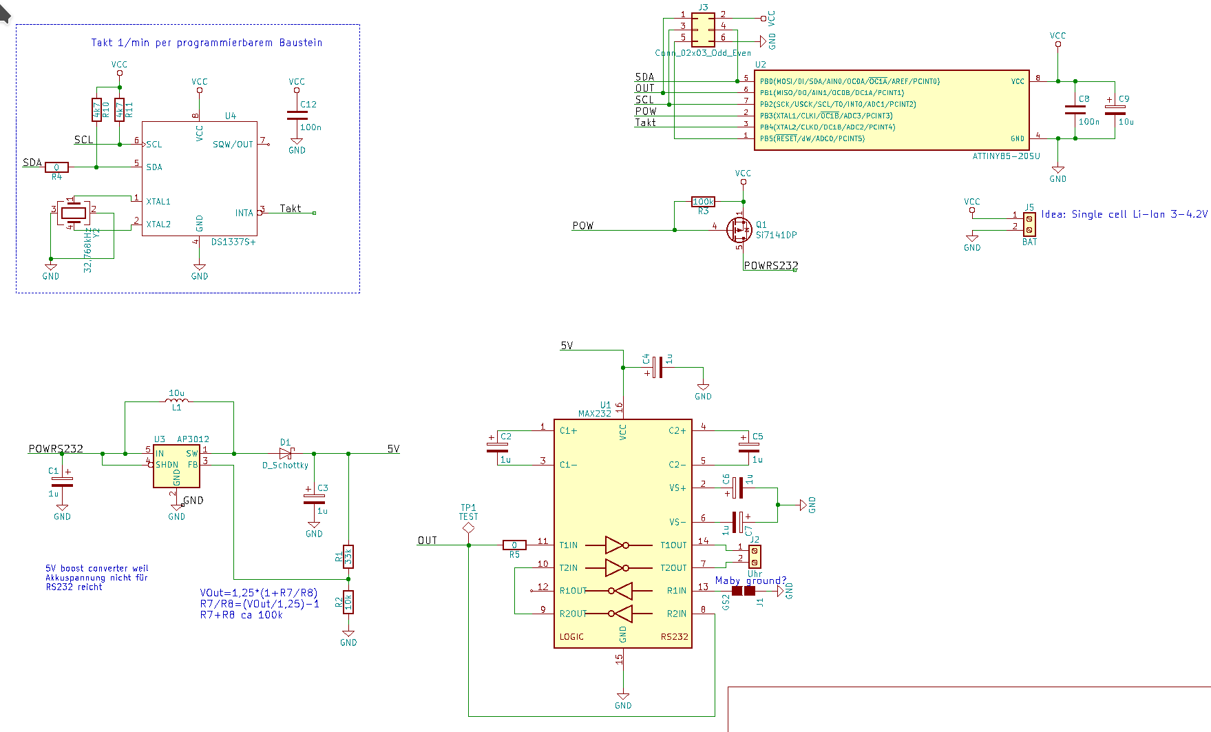
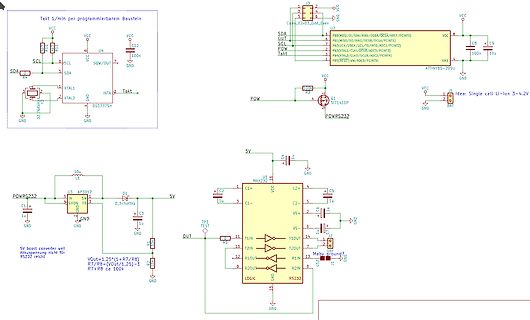
VCC, SCL, SDA, C12, 100n, U4, XTAL1, XTAL2, DS13375+, TAKT, U2, ATtiny85-20SC, GND, POW, C8, 10u, 5V, U3, AP31012, C4, 10u, C3, 1u, D_Schottky, 5V, U1, MAX232, C1+, C2+, C5, 1u, C1-, C2-, VS+, VS-, T1IN, T1OUT, T2IN, T2OUT, R1IN, R2IN, R10OUT, R2OUT, LOGIC, RS232, 5V boost converter, Akkuentspannung nicht für RS232 reicht, Vout=1,25*(1+R7/R8), R7/R8=(Vout/1,25)-1, R7+R8 ca 100k
in „Telenorma Nebenuhr: Schaltung für Minutenimpuls mit AVR“ · Mikrocontroller und Digitale Elektronik · · Schaltpläne
-
PDF
tps2552.pdf
≤ 232 kΩ. To: where 15 kΩ ≤ R ILIM ≤ 232 kΩ. ........................................................ 15 • Changed Figure 23 - Current-Limit Threshold vs R ILIM ...........................................
in „Problem mit FSUSB30 als USB-Schalter“ · Mikrocontroller und Digitale Elektronik ·
-
PDF
DS1000Z_Firmware_Release_Notes.pdf
Instrument Firmware Release Notes Models DS1054Z, DS1074Z, DS1104Z, DS1054Z-S, DS1074Z-S, DS1104Z-S, MSO1074Z, MSO1104Z, MSO1074Z-S, MSO1104Z-S VersionInformation Releasedversion:00.04.03.01.05 ReleaseDate:6/16/2015 Compatibility Compatiblewithearlierversionsof
in „Rigol-DS1054Z“ · Mikrocontroller und Digitale Elektronik ·
-
Datei
Devices.txt
0603_1608R 6 RACON12 6 PTR1B1,27 6 PMD 6 PE012 6 NE5534N 6 MKDSN1,5/3-5,08 6 MEGA32-A 6 MBRS240 6 MAX232ECWES 6 MA10-1 6 MA06-1 6 LM358N 6 LM317TL 6 L-EU0207/12 6 L298 6 KLEMM2 6 IRFR5305 6 IRF512 6 HD-F103 6 HD-A101 6 FS6 6 F09DS 6 ENC28J60-DIL 6 DIODE-D-2.5 6 DIODE-10 6 CRYSTALHC49U-V 6 CQ1-12V 6 CPOL-EUE5
in „[KiCad] Bibliotheksaufbau - Konzeptideen gesucht“ · Platinen ·