-
Datei
max7219.h
/* * max7219.h * * Created on: 30.04.2016 * Author: harry */ #ifndef MAX7219_H_ #define MAX7219_H_ void init_max7219(void); void set_brightness_max7219(uint8_t brightness); void set_digit_max7219(uint8_t digit, uint8_t val); void set_val_max7219(int32_t val, uint8_t dpoint); #endif /* MAX7219_H_ */
in „8x8 g click mit STM32“ · Mikrocontroller und Digitale Elektronik ·
-
Datei
max7219.h
/* * max7219.h * * Created on: 30.04.2016 * Author: harry */ #ifndef MAX7219_H_ #define MAX7219_H_ void init_max7219(void); void set_brightness_max7219(uint8_t brightness); void set_digit_max7219(uint8_t digit, uint8_t val); void set_val_max7219(int32_t val, uint8_t dpoint); #endif /* MAX7219_H_ */
in „Bit Banging STM32 - F303RE ohne Library“ · Mikrocontroller und Digitale Elektronik ·
-
Datei
cMax7219.h
_____| >>> ******************************************************************************/ #ifndef MAX7219_HPP #define Max7219_HPP #include <pinlist.h> // mcucpp #include <delay.h> // delay <us,F_CPU>() #include <drivers/c7segments_.h> // add_char | CharMap(char) namespace Mcucpp { //****************
in „AVR und C++ - ein Versuch“ · Mikrocontroller und Digitale Elektronik ·
-
Datei
ICP_Drehzahl.c
uint32_t zwischenwert = 0; uint32_t frequenz = 0; uint32_t drehzahl = 0; char buffer[6]; //***********max7219/Display****************************************** //!!!!max7219 Routinen!!!! void static ausgabe(void) { max7219_Init(); transmit(0x01,buffer[0]); //Display 0 transmit(0x02,buffer[1]); //Display
in „Frage zu Timereinsatz (Atmega8/Frequenzzähler/Drehgebercode)“ · Mikrocontroller und Digitale Elektronik ·
-
Datei
max7219.c
=0x00; DDRD=0x07; write_max7219 (0x09, 0x00); // Dekodieren ausschalten write_max7219 (0x0b, 0x07); // 8 Digits write_max7219 (0x0c, 0x01); // Display an write_max7219 (0x0f, 0x00); // Testmode aus write_max7219 (0x0a, 0x0a); // Helligkeit write_max7219 (0x01, 0x0f); // Daten in Spalte 1 while (1) { }; }
in „Problem mit MAX7219“ · Mikrocontroller und Digitale Elektronik ·
-
Datei
max7219.c
= (1<<2); DDRD &= ~(1<<3); // PORTB als Eingang - Taster PORTD |= (1<<3); // PORTB0 auf High write_max7219 (0x09, 0x00); // Dekodieren ausschalten write_max7219 (0x0b, 0x07); // 8 Digits write_max7219 (0x0c, 0x01); // Display an write_max7219 (0x0f, 0x00); // Testmode aus write_max7219 (0x0a, 0x0a); // Helligkeit write_max7219 (0x01, 0x0f); // Daten in Spalte 1 while (1) { }; return 0; }
in „LED Matrix Max7219 Ansterung funktioniert nicht“ · Mikrocontroller und Digitale Elektronik ·
-
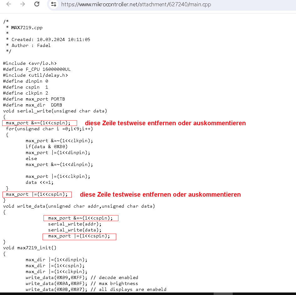
 Bild
Bild
C++ Quellcode für AVR Mikrocontroller
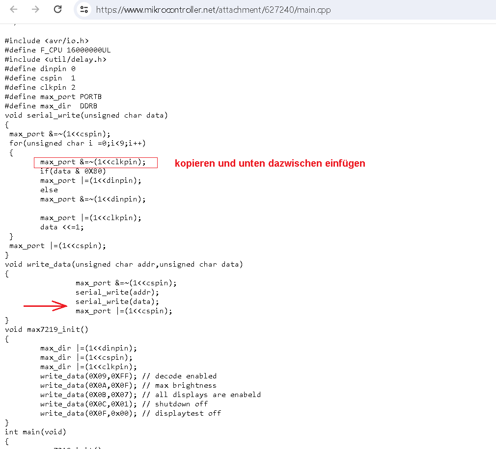
https://www.mikrocontroller.net/attachment/627240/main.cpp /* * MAX7219.cpp * * Created: 10.03.2024 10:11:05 * Author : Fadel */ #include <avr/io.h> #define F_CPU 16000000UL #include <util/delay.h> #define dinpin 0 #define cspin 1 #define clkpin 2 #define max_port PORTB
in „Atmega32 und MAX7219“ · Mikrocontroller und Digitale Elektronik · · Screenshots
-
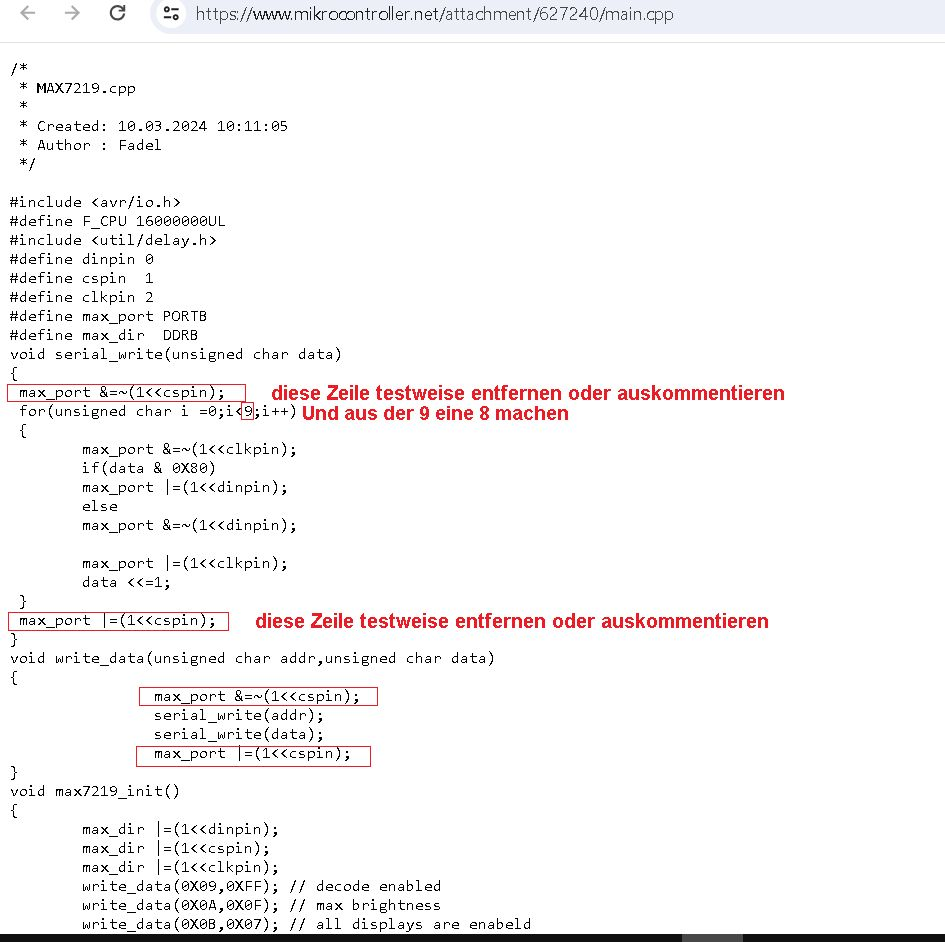
 Bild
Bild
C-Quellcode für Mikrocontroller
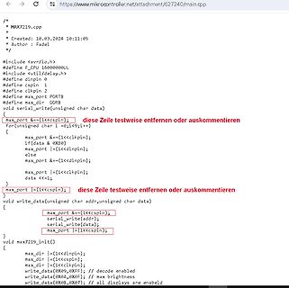
/* * MAX7219.cpp * * Created: 10.03.2024 10:11:05 * Author : Fadel */ #include <avr/io.h> #define F_CPU 16000000UL #include <util/delay.h> #define dinpin 0 #define cspin 1 #define clkpin 2 #define max_port
in „Atmega32 und MAX7219“ · Mikrocontroller und Digitale Elektronik · · Screenshots
-
Datei
MAX7219.c
#include "Max7219.h" //Max7129 Zeichentabelle const uint8_t chars[] = {126,48,109,121,51,91,95,112,127,123}; uint8_t black_digit = 9; void Load_Low(void) { PORTB &= ~(1 << PB2); } void Load_High(void) { PORTB |=
in „code ummodeln??“ · Mikrocontroller und Digitale Elektronik ·
-
Datei
MAX7219.h
#include <avr/io.h> #ifndef MAX7219 #define MAX7219 #define MAX_MODE_SLEEP 0x00 #define MAX_MODE_NORMAL 0x01 //Max7129 Zeichentabelle extern const uint8_t chars[]; void transmit(unsigned char addr, char data); void Load_Low(void);
in „code ummodeln??“ · Mikrocontroller und Digitale Elektronik ·
-
Datei
MAX7219.inc
init_max: push temp2 push temp3 ldi temp,0b11111110 ; LED aus, MAX high out PORTD,temp ; Daten - Data Port D ; Decode-Mode: no decode ldi tmp,0x09 ; Adresse des Decode Mode Registers call SEND_SPIDATA ldi tmp,0x00 ; keine Decodierung call SEND_SPIDATA sbi PORTB, 4 nop cbi PORTB, 4 ; Intensity auf Maximum stellen: ldi tmp,0x0A call SEND_SPIDATA ldi tmp,0x0F call SEND_SPIDATA sbi PORTB, 4 nop cbi PORTB, 4 ; Scan Limit auf 8 aktive Displays stellen: ldi tmp,0x0B call SEND_SPIDATA ldi tmp,0x07 call SEND_SPIDATA sbi PORTB, 4 nop cbi PORTB, 4 ; Display test mode = off: ldi tmp,0x0F ; Adresse des Display
-
Datei
MAX7219.inc
init_max: push temp2 push temp3 ldi temp,0b11111110 ; LED aus, MAX high out PORTD,temp ; Daten - Data Port D ; Decode-Mode: no decode ldi tmp,0x09 ; Adresse des Decode Mode Registers call SEND_SPIDATA ldi tmp,0x00 ; keine Decodierung call SEND_SPIDATA sbi PORTB, 4 nop cbi PORTB, 4 ; Intensity auf Maximum stellen: ldi tmp,0x0A call SEND_SPIDATA ldi tmp,0x0F call SEND_SPIDATA sbi PORTB, 4 nop cbi PORTB, 4 ; Scan Limit auf 8 aktive Displays stellen: ldi tmp,0x0B call SEND_SPIDATA ldi tmp,0x07 call SEND_SPIDATA sbi PORTB, 4 nop cbi PORTB, 4 ; Display test mode = off: ldi tmp,0x0F ; Adresse des Display
in „MAX7219 Mega8535“ · Mikrocontroller und Digitale Elektronik ·
-
 Bild
Bild
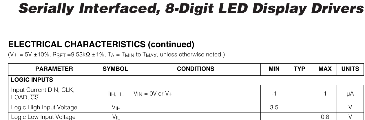
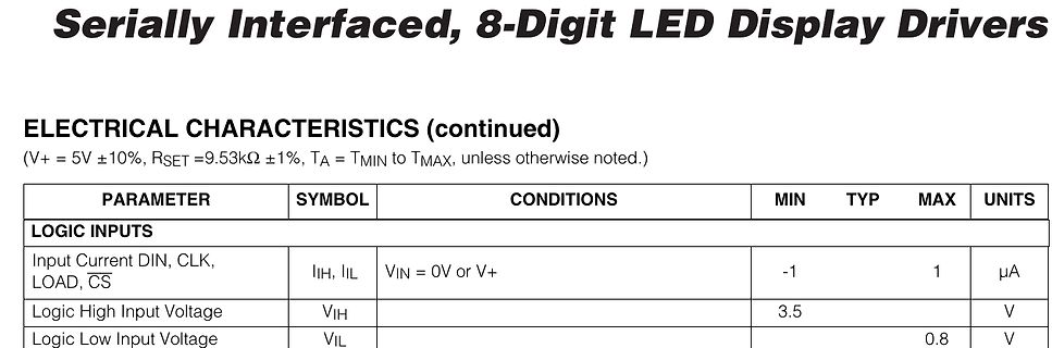
Ausschnitt aus einem Datenblatt mit elektrischen Kennwerten
Serially Interfaced, 8-Digit LED Display Drivers ELECTRICAL CHARACTERISTICS (continued) (V+ = 5V ±10%, RSET =9.53kΩ ±1%, TA = TMIN to TMAX, unless otherwise noted.) PARAMETER SYMBOL CONDITIONS MIN TYP MAX UNITS LOGIC INPUTS Input Current DIN, CLK, LOAD, CS IIH, IIL VIN = 0V or V+ -1 1 µA Logic High Input Voltage VIH 3.5 V Logic Low Input Voltage VIL 0.8 V
in „Bit Banging STM32 - F303RE ohne Library“ · Mikrocontroller und Digitale Elektronik · · Screenshots
-
Datei
MAX7219.h
============================================================ // Das ist die Header datei um den IC Max7219 zu Initialisieren // ohne die Initialisierung könnte man den IC nicht Ansteuern //======================================================================================= //**********************
in „LED Modul 8x8“ · Mikrocontroller und Digitale Elektronik ·
-
Datei
Max7219_.c
//***************************************************************************** // cMax7219 //***************************************************************************** // first try //****************************************************************************** // MAX7219/21 // ***
in „MAX7219: 3-Segment-Anzeige macht Probleme“ · Mikrocontroller und Digitale Elektronik ·
-
Datei
max7219.h
#ifndef MAX_7219_H #define MAX_7219_H #include <avr/io.h> #include "../../global_files/io_port.h" class max7219{ public: void initPort(void); void sendAllCmdData(uint8_t cmd, uint8_t data); void sendCmdData(uint8
in „Probleme bei der Ansteuerung MAX7219 mit 8x8 Dot Matrix“ · Mikrocontroller und Digitale Elektronik ·
-
Datei
main.c
**********************************************************************************************/ /* MAX7219 Functionen */ /***********************************************************************************************************************/ void max7219_init2 (void) { uint8_t cnt; // Set the MAX7219
in „Serienschaltung von 2 MAX7219“ · Mikrocontroller und Digitale Elektronik ·
-
Datei
7219M_K_Net_2.txt
######################## ###################################################################### //7219.c #include "7219.h" //********************************************************************************************** //senden // zum MAX schieben void shift_7219(uint8_t data) { for (uint8_t i = 8;i
in „7219 funzt nicht mit Atmega8“ · Mikrocontroller und Digitale Elektronik ·
-
Datei
7219f_rM_Net.txt
)) //------------------------------------------------------------------------------------------ //7219 FUNKTIONEN extern void send_7219(uint8_t, uint8_t ); extern void shift_7219(uint8_t); extern void init_7219(void); //---------------------------------------------------------------------------------
in „7219 funzt nicht mit Atmega8“ · Mikrocontroller und Digitale Elektronik ·
-
Datei
main_funktioniert.cpp
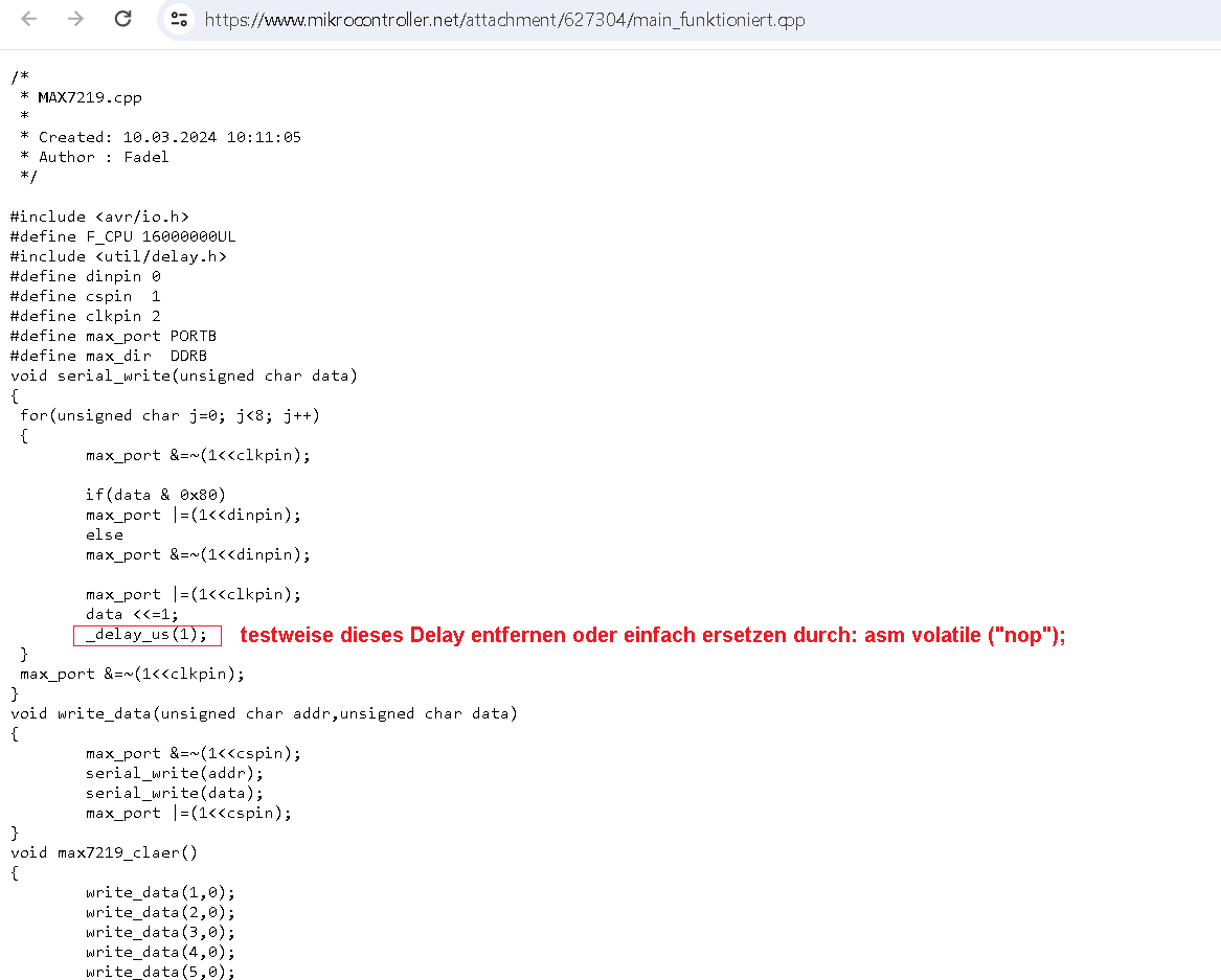
/* * MAX7219.cpp * * Created: 10.03.2024 10:11:05 * Author : Fadel */ #include <avr/io.h> #define F_CPU 16000000UL #include <util/delay.h> #define dinpin 0 #define cspin 1 #define clkpin 2 #define max_port PORTB
in „Atmega32 und MAX7219“ · Mikrocontroller und Digitale Elektronik ·
-
 Bild
Bild
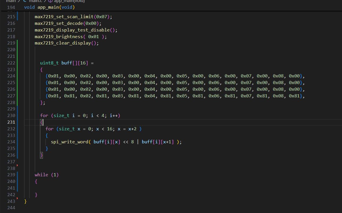
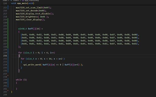
C-Quellcode zur Steuerung eines Displays
void app_main(void) max7219_set_scan_limit(0x07); max7219_set_decode(0x00); max7219_display_test_disable(); max7219_brightness( 0x01 ); max7219_clear_display(); uint8_t buff[][16] = { {0x01, 0x00, 0x02, 0x00, 0x03, 0x00, 0x04
in „MAX7219 > Bytes und Timing“ · Mikrocontroller und Digitale Elektronik · · Screenshots
-
Datei
MAX7219_8.ino
} 4, 8, B00001000, B00000100, B00001000, B00000100, B00000000, // ~ }; int data = 8; // DIN pin of MAX7219 module int load = 9; // CS pin of MAX7219 module int clock = 10; // CLK pin of MAX7219 module int maxInUse = 4; //change this variable to set how many MAX7219's you'll use MaxMatrix m(data, load
in „LED Matrix MAX7219 8x8 an Arduino will nicht.“ · Mikrocontroller und Digitale Elektronik ·
-
Datei
GccAtmega8515_MAX7219_quad.c
/ scan digits 0-7 SPI4_Transmit(0x09,0xFF,0x09,0xFF,0x09,0xFF,0x09,0xFF); // Code B for all } void max7219_Clear (void) { char i; for (i=0; i < 9; i++) SPI4_Transmit(i,0x0F,i,0x0F,i,0x0F,i,0x0F); } int main (void) { DDRC = 0xFF; // PORT C als Ausgang schalten PORTC = 0xFF; // alle LEDs aus (invertiert wegen STK500) SPI_MasterInit(); // SPI initialisieren max7219_4_Init(); // MAX initialisieren while(1) { // max7219_4_Init(); // max7219_Clear(); PORTC = 0xFF; // LED0 blinkt mit 1Hz _delay_ms(500); PORTC = 0xFE; _delay_ms(500); // SPI_Transmit(DigitAnzeige1
in „ATMEGA8515_SPI ->4-fach MAX7219 instabil, Fragen dazu“ · Mikrocontroller und Digitale Elektronik ·
-
Datei
Configuration_adv.h
its usage. */ //#define MAX7219_DEBUG #if ENABLED(MAX7219_DEBUG) #define MAX7219_CLK_PIN 64 #define MAX7219_DIN_PIN 57 #define MAX7219_LOAD_PIN 44 //#define MAX7219_GCODE // Add the M7219 G-code to control the LED matrix #define MAX7219_INIT_TEST 2 // Do a test pattern at initialization (Set to 2 for spiral) #define MAX7219_NUMBER_UNITS 1 // Number of Max7219 units in chain. #define MAX7219_ROTATE 0 // Rotate the display clockwise
in „Marlin Firmware mit dem ATMEL STUDIO 7 auf das Arduino Mega 2560 Board flashen“ · Mikrocontroller und Digitale Elektronik ·
-
Datei
main_gek_rzt.c
= 8,33 Hz * 1000 (Segmente)-> 2 * 8,33kHz = 17kHz -> interrupt alle 0,000059 Sekunden nötig 8bit = max bis 256 -> timer = 4000000Hz/17000 = 235 TcNT0 = 256 - 235= 21 Interupt löst somit alle 0,000059 Sekunden aus ************************************************************/ TCCR0 = (1<<CS00); // prescaler
in „Frage zu Timereinsatz (Atmega8/Frequenzzähler/Drehgebercode)“ · Mikrocontroller und Digitale Elektronik ·
-
Datei
main.cpp
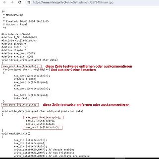
/* * MAX7219.cpp * * Created: 10.03.2024 10:11:05 * Author : Fadel */ #include <avr/io.h> #define F_CPU 16000000UL #include <util/delay.h> #define dinpin 0 #define cspin 1 #define clkpin 2 #define max_port PORTB
in „Atmega32 und MAX7219“ · Mikrocontroller und Digitale Elektronik ·
-
 Bild
Bild
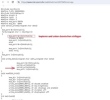
C-Quellcode für Mikrocontroller
define CPU 16000000UL #include <util/delay.h> #define dinpin 0 #define cspin 1 #define clkpin 2 #define max_port PORTB #define max_dir DDRB void serial_write(unsigned char data) { max_port &= ~(1<<cspin); for(unsigned char i=0;i<9;i++) { max_port &= ~(1<<clkpin); if(data & 0x80) max_port |= (1<<dinpin); else
in „Atmega32 und MAX7219“ · Mikrocontroller und Digitale Elektronik · · Screenshots
-
 Bild
Bild
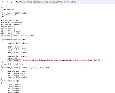
C++ Quellcode für Mikrocontroller
https://www.mikrocontroller.net/attachment/627304/main_funktionirt.cpp /* * MAX7219.cpp * * Created: 10.03.2024 10:11:05 * Author : Fadel */ #include <avr/io.h> #define F_CPU 16000000UL #include <util/delay.h> #define dinpin 0 #define cspin 1 #define clkpin 2 #define max_port PORTB
in „Atmega32 und MAX7219“ · Mikrocontroller und Digitale Elektronik · · Screenshots
-
Datei
Configuration_adv.h
its usage. */ //#define MAX7219_DEBUG #if ENABLED(MAX7219_DEBUG) #define MAX7219_CLK_PIN 64 #define MAX7219_DIN_PIN 57 #define MAX7219_LOAD_PIN 44 //#define MAX7219_GCODE // Add the M7219 G-code to control the LED matrix #define MAX7219_INIT_TEST 2 // Do a test pattern at initialization (Set to 2 for spiral) #define MAX7219_NUMBER_UNITS 1 // Number of Max7219 units in chain. #define MAX7219_ROTATE 0 // Rotate the display clockwise
in „Marlin 2.0.72 lässt sich nicht compilieren“ · Mikrocontroller und Digitale Elektronik ·
-
PDF
stm32_magic_eye2.pdf
5 L06 L00 2 C 18 1 8 L07 1A0 C 1Y0 DIN DIG7 H00 H01 H02 H03 H04 H05 H06 H07 4 1A1 V 1Y1 16 13 CLK MAX7219 6 14 12 SEG_DP 22 H00 1A2 1Y2 CS SEG_A 14 H01 8 1A3 1Y3 12 16 H02 D9 D10 D11 D12 D13 D14 D15 D16 17 3 SEG_B LED LED LED LED LED LED LED LED 2A0 2Y0 SEG_C 20 H03 15 2A1 2Y1 5 23 H04 13 7 SEG_D L01
in „STM32F103 und I2S Probleme“ · Mikrocontroller und Digitale Elektronik ·
-
Datei
laufschr.asm
***************************** ;* LAUFSCHR.ASM V2.2b * ;* Laufschrift-Anzeige mit LEDs * ;* Mehrere MAX7219 kaskadiert, Module mit jeweils * ;* 8x8 LEDs; Zeichensatz 5x8 * ;* Assemblerprogramm fuer 8051-kompatible Controller, * ;* z.B. AT89C51, Quarzfrequenz 11,0592 MHz * ;* Das nachfolgende Programm
in „Anstuerung MAX6952 an einen 89C2051 oder einen PIC“ · Mikrocontroller und Digitale Elektronik ·
-
Datei
Configuration_adv.h
its usage. */ //#define MAX7219_DEBUG #if ENABLED(MAX7219_DEBUG) #define MAX7219_CLK_PIN 64 #define MAX7219_DIN_PIN 57 #define MAX7219_LOAD_PIN 44 //#define MAX7219_GCODE // Add the M7219 G-code to control the LED matrix #define MAX7219_INIT_TEST 2 // Test pattern at startup: 0=none, 1=sweep, 2=spiral #define MAX7219_NUMBER_UNITS 1 // Number of Max7219 units in chain. #define MAX7219_ROTATE 0 // Rotate the display clockwise (in
in „Ender3 Z-Achse fährt mit Marlin nur nach oben“ · Mechanik, Gehäuse, Werkzeug ·
-
Datei
test.asm
INC rmp RJMP BintoDigita BintoDigitc: ST z+,rmp RET ;*********************************************MAX7219initialisieren******************************** Ausgabe_init: LDI temp2,0x09 ;decode address LDI temp1,0x0F ;decode digit 3-0 RCALL Ausgabe LDI temp2,0x0A ;helligkeit address LDI temp1,0x0F ;max hell
in „Led Display“ · Mikrocontroller und Digitale Elektronik ·
-
Datei
Code.txt
connected to digital pin 6 on the arduino and the CLK on digital pin 7 int DIN = 6; // DIN pin of MAX7219 module int CLK = 7; // CLK pin of MAX7219 module int CS = 8; // CS pin of MAX7219 module int maxInUse = 14; //Change this number to the amount of matrixes you linked together byte counter = 0; byte
in „Max7219 an Arduino Nano will nicht“ · Mikrocontroller und Digitale Elektronik ·
-
Datei
Protogen_OS_V3.1_mod__1_.ino
connected to digital pin 6 on the arduino and the CLK on digital pin 7 int DIN = 6; // DIN pin of MAX7219 module int CLK = 7; // CLK pin of MAX7219 module int CS = 8; // CS pin of MAX7219 module int maxInUse = 14; //Change this number to the amount of matrixes you linked together byte counter = 0; byte
in „Max7219 an Arduino Nano will nicht“ · Mikrocontroller und Digitale Elektronik ·
-
Datei
test.asm
inc rmp rjmp BintoDigita BintoDigitc: st z+,rmp ret ;*********************************************MAX7219 initialisieren************************************* Ausgabe_init: ldi temp2,0x09 ;decode address ldi temp1,0xFF ;decode digit 7-0 rcall Ausgabe ldi temp2,0x0A ;helligkeit address ldi temp1,0x0F
-
PDF
max7219_4inchLED.pdf
max7219_4inchLED.pdf
in „8 x 8 x 7-Segment Anzeigen per PC ansteuern“ · Mikrocontroller und Digitale Elektronik ·
-
PDF
Winkelmesser2.sch.pdf
c 23 2 d SEGD 21 1 19 SEGE 15 9 e VCC SEGF f 4 GND SEGG 17 10 g DP 5 9 GND SEGDP 22 7-SEG_SA10-21 MAX7219CNG LED12 7 a A 3 6 b A 8 4 c 2 GND d 1 e 9 f 10 g 5 DP 7-SEG_SA10-21 10.07.2009 13:15:46 C:\Dokumente und Einstellungen\user\Eigene Dateien\Eagle\Winkelmesser2.sch (Sheet: 1/1) IC4 13 2 CLK DIG0
in „12 Stk. 7Seg.-Anzeigen Multiplexen“ · Mikrocontroller und Digitale Elektronik ·
-
PDF
Winkelmesser3.sch.pdf
c SEGD 23 2 d SEGE 21 1 e 19 15 9 f 4 VCC SEGF 17 10 5 9 GND SEGG 22 g DP GND SEGDP 7-SEG_SA10-21 MAX7219CNG LED12 7 3 6 a A 8 b A 4 c GND 2 d 1 e 9 f 10 g DP 5 7-SEG_SA10-21 10.07.2009 13:43:58 C:\Dokumente und Einstellungen\user\Eigene Dateien\Eagle\Winkelmesser3.sch (Sheet: 1/1) IC4 13 2 CLK DIG0
in „12 Stk. 7Seg.-Anzeigen Multiplexen“ · Mikrocontroller und Digitale Elektronik ·
-
Datei
matrix_1.c
mit ATMEGA48 Andreas Weschenfelder 22.07.06 Ansteuerung der 8x8 Matrix ueber SPI CS-Ansteuerung mit MAX7219 nicht moeglich Taktfrequenz 12Mhz *****************************************************************************/ #include <math.h> #include <avr/io.h> #include <avr/delay.h> #include <stdlib.h>
-
Datei
rpn_boris_A328_v1.7.bas
inputkey As Byte) As Byte ' Unterscheiden Ziffer oder Kommando ' Anzeigefunktionen Declare Sub Init_max7219() ' Initialisierung der Anzeige, Helligkeit, Modus u.s.w. Declare Sub Anzeigen() ' Schleife ueber das Anzeigefeld, Umwandlung in 7segmentcode Declare Sub Interpr_rx () ' Die Anzeigefunktion, wir
in „Noch ein Taschenrechner auf ATMega Basis“ · Projekte & Code ·
-
Datei
rpn_boris_A328_v1.8.bas
inputkey As Byte) As Byte ' Unterscheiden Ziffer oder Kommando ' Anzeigefunktionen Declare Sub Init_max7219() ' Initialisierung der Anzeige, Helligkeit, Modus u.s.w. Declare Sub Anzeigen() ' Schleife ueber das Anzeigefeld, Umwandlung in 7segmentcode Declare Sub Interpr_rx() ' Die Anzeigefunktion, wir
in „Noch ein Taschenrechner auf ATMega Basis“ · Projekte & Code ·
-
Datei
rpn_boris_A328_v1.9.bas
inputkey As Byte) As Byte ' Unterscheiden Ziffer oder Kommando ' Anzeigefunktionen Declare Sub Init_max7219() ' Initialisierung der Anzeige, Helligkeit, Modus u.s.w. Declare Sub Anzeigen() ' Schleife ueber das Anzeigefeld, Umwandlung in 7segmentcode Declare Sub Interpr_rx() ' Die Anzeigefunktion, wir
in „Noch ein Taschenrechner auf ATMega Basis“ · Projekte & Code ·
-
PDF
Frequenzzaehler_-_die_zweite.pdf
Semiconductor: tive, sich auf das Schnorren eines fertigen schnellen Komparators zu verlegen. LMV7219M5, 7 ns, nur 1.1 mA, 7 mV Hy- sterese, Frequenz nicht angegeben, meine Aber eines darf man nicht übersehen: Alle Schätzung 60..70 MHz. Für uns ein bissel diese Komparatoren sind langsamer als UHS- langsam
in „PIC - Frequenzzähler weit über 50 MHz auf die minimalistische Art“ · Mikrocontroller und Digitale Elektronik ·
-
PDF
ElektronikBauteile.pdf
Kurzhubtaster 6x6mm, Höhe: 7,0mm, 12V, vertikal TASTER 9303 0,12 € 2,40 € 66 10 RS232-Driver, DIL-16 MAX 232 CPE 0,32 € 3,20 € 67 2 Schnittstellenbaustein, SOL-16 MAX 202 ECWE 1,30 € 2,60 € 68 26 Pfostenbuchse, 10-polig, mit Zugentlastung PFL 10 0,09 € 2,39 € 69 10 Wannenstecker, 10-polig, gerade WSL 10G
in „[V] - Elektroniksammlung“ · Markt ·
-
Datei
max7221.h
#ifndef MAX7221_H_ #define MAX7221_H_ // Definieren Chip Select MAX7221 #define CS_HIGH() P2OUT |= 0x01 #define CS_LOW() P2OUT &= 0xFC // Definieren der Operation Codes MAX7219/MAX7221 #define OP_NOOP 0x00 #define
in „Problem mit Ansteuerung MAX7221“ · Mikrocontroller und Digitale Elektronik ·
-
Datei
rpn_boris_A328_v1.12.bas
inputkey As Byte) As Byte ' Unterscheiden Ziffer oder Kommando ' Anzeigefunktionen Declare Sub Init_max7219() ' Initialisierung der Anzeige, Helligkeit, Modus u.s.w. Declare Sub Anzeigen() ' Schleife ueber das Anzeigefeld, Umwandlung in 7segmentcode Declare Sub Interpr_rx() ' Die Anzeigefunktion, wir
in „Noch ein Taschenrechner auf ATMega Basis“ · Projekte & Code ·
-
Datei
rpn_boris_A328_v1.13.bas
inputkey As Byte) As Byte ' Unterscheiden Ziffer oder Kommando ' Anzeigefunktionen Declare Sub Init_max7219() ' Initialisierung der Anzeige, Helligkeit, Modus u.s.w. Declare Sub Anzeigen() ' Schleife ueber das Anzeigefeld, Umwandlung in 7segmentcode Declare Sub Interpr_rx() ' Die Anzeigefunktion, wir
in „Noch ein Taschenrechner auf ATMega Basis“ · Projekte & Code ·
-
Datei
rpn_boris_A328_v1.13.bas
inputkey As Byte) As Byte ' Unterscheiden Ziffer oder Kommando ' Anzeigefunktionen Declare Sub Init_max7219() ' Initialisierung der Anzeige, Helligkeit, Modus u.s.w. Declare Sub Anzeigen() ' Schleife ueber das Anzeigefeld, Umwandlung in 7segmentcode Declare Sub Interpr_rx() ' Die Anzeigefunktion, wir
in „Noch ein Taschenrechner auf ATMega Basis“ · Projekte & Code ·
-
Datei
rpn_boris_A328_v1.14.bas
inputkey As Byte) As Byte ' Unterscheiden Ziffer oder Kommando ' Anzeigefunktionen Declare Sub Init_max7219() ' Initialisierung der Anzeige, Helligkeit, Modus u.s.w. Declare Sub Anzeigen() ' Schleife ueber das Anzeigefeld, Umwandlung in 7segmentcode Declare Sub Interpr_rx() ' Die Anzeigefunktion, wir
in „Noch ein Taschenrechner auf ATMega Basis“ · Projekte & Code ·