-
Datei
lcd_io1.h
PORT(X) and DDR(X) ) elsewhere in your program otherwise your program will crash and you will have a lot of fun for the whole family (again!). Use sbi() and cbi() commands instead. MODE 3 INFORMATION mode 3 uses the I2C bus and a PCF8574. Up to 8 different lcd units can be connected. You also need to make a very simple cirquit with PCF8574 (one for each lcd). Also the pins can be scattered all over the place (any LCD pin in any PCF8574 port pin). You must also have an I2C Master driver (preferably my I2C
-
Datei
lcd_io1.h
PORT(X) and DDR(X) ) elsewhere in your program otherwise your program will crash and you will have a lot of fun for the whole family (again!). Use sbi() and cbi() commands instead. MODE 3 INFORMATION mode 3 uses the I2C bus and a PCF8574. Up to 8 different lcd units can be connected. You also need to make a very simple cirquit with PCF8574 (one for each lcd). Also the pins can be scattered all over the place (any LCD pin in any PCF8574 port pin). You must also have an I2C Master driver (preferably my I2C
in „LCD I2C Bibliothek“ · Mikrocontroller und Digitale Elektronik ·
-
Datei
PCF-Test-2c.c
/* PCF-Test-2c.c * * Erste Korrektur von PCF-Test-2c.c: * nicht die Ports schalten, sondern nur die Datenrichtungen, den Rest * erledigten die Pullups. * * Test eines PCF8574A: reagiert er auf die Eingabe
in „Software-TWI: enge Clock-Frequenz oder beliebige Zeiten?“ · Mikrocontroller und Digitale Elektronik ·
-
PDF
Projekt_Heimautomation.pdf
Konflikt kommt. Widerständebenötigt.Diehabeichnichtvergessen. Den I2C-Bus benötige ich, um mit dem PCF8574 zu kommunizieren. - Die SPI-Schnittstelle befindet sich auf den Pins 19, 21, 23 und 24, wobei der Pin 24 der CS-Pin ist und PCF8574 – S0-Zähler DasCAN-InterfacebestehtimWesentlichenauszweiBau- teilen
in „Schaltplan für Haussteuerung im Hutschienengehäuse (Raspberry Pi, CAN, MCP2515, MCP2562, PCF8574)“ · Haus & Smart Home ·
-
Datei
T6963c.c
for using with T6963cInit() //Macros for Bitbanging volatile unsigned char cmd_data=0; uint8_t readPCF8574A_DATA() { uint8_t ret_data=0; i2c_start_wait(PCF8574A_DATA_Address+1); ret_data=i2c_readNak(); i2c_stop(); return ret_data; } void writePFC8574A(uint8_t cmd, unsigned char data) { if (cmd) { i2c_start_wait(PCF8574A_CMD_Address+0); } else { i2c_start_wait(PCF8574A_DATA_Address+0); } i2c_write(data); i2c_stop(); } void T6963C_RESET_ENABLE() // T6963C_PORT_CTRL &= ~(1<<T6963C_RST) { cmd_data &= ~(1<<T6963C_RST
in „Problem mit T6963c bei Umstellung auf I2C“ · Mikrocontroller und Digitale Elektronik ·
-
Datei
ATMEGA328P_Test.bas
I2C Config Sda = Portb.1 'SDA I2C Config I2cdelay = 1 'Wert für I2C-Port Dim _lcd_e As Byte Const Pcf8574_lcd = 78 'Address of I2C-LCD = 78 Enable Interrupts Config Int0 = Falling 'Int signal from PCF8574_KBD is connected to INT0 Const PCF_D4 = 4 ' Pin assignments for connection PCF8574 to LCD Const PCF_D5 = 5 Const PCF_D6 = 6 Const PCF_D7 = 7 Const PCF_RS = 0 Const PCF_RW = 1 Const PCF_E2 = 3 Const PCF_E1 = 2 '_lcd_e = 128 select E1, 64 select E2, 192 select both (for CLS or DefLCDChar etc.) _lcd_e
in „BASCOM AVR YwRobot_Lcd_i2c.lib für 1602 LCD anpassen“ · Mikrocontroller und Digitale Elektronik ·
-
Datei
PCF-Test-2a.c
/* * Test eines PCF8574A: reagiert er auf die Eingabe seiner Adresse mit Ack? * Bei erhaltenem Ack sollte die eine, bei nicht erhaltenem Ack die andere LED * blinken. * * Hardware: Board mit Atmega 644P und PCF8574A. Der PCF8574A ist mit SDA und SCL * gem. Manual verbunden - mit 10-k-Pullups. */ #include <util/twi.h> #include <avr/io.h> #include <util/delay.h> #include <i2cmaster.h> #define SCL PC0 // für PCF8574A #define
in „Software-TWI: enge Clock-Frequenz oder beliebige Zeiten?“ · Mikrocontroller und Digitale Elektronik ·
-
PDF
Elektronik_Sortimente.pdf
with 240 x 8-bit RAM (PCF8583) 5-10x 16-channel, 12-bit PWM Fm+ I2C-bus LED controller (PCA9685) 5x 16 CHANNEL LED DRIVER WITH DOT CORRECTION AND GRAYSCALE PWM CONTROL (TLC5940NT) 5x 8-bit I/O expander for I2C-bus (PCF8574, PCA8574, PCA8574A) 5x 16-Bit I/O Expander with Serial Interface (MCP23017) 20x Remote 8-bit I/O expander for I2C-bus (PCF8574) 10x Remote 8-bit I/O expander for I2C-bus (PCF8574A) 10x 8-bit A/D and D/A converter
in „Einkaufsliste für die Einrichtung eines Elektronik-Labors“ · Mikrocontroller und Digitale Elektronik ·
-
Datei
_3_I2C_Routinen.asm
PINB .equ SCLREAD = PINB .equ SCL = 0 ; Pin für Serial Clock .equ SDA = 1 ; Pin für Serial Data .equ PCF8574W = 0x40 ; Porterweiterung, Systemadresse des PCF8574 -> 0100 000 0 = 40 hex = 64 dez, Schreibmodus .equ PCF8574R = 0x41 ; Porterweiterung, Systemadresse des PCF8574 -> 0100 000 1 = 41 hex = 65 dez, Lesemodus .equ PCF8573W = 0xD0 ; Real Time Clock, Systemadresse des PCF8573 -> 1101 000 0 = D0 hex =208 dez, Schreibmodus .equ PCF8573R = 0xD1 ; Real Time Clock, Systemadresse des PCF8573 -> 1101 000 1 = D1 hex =209 dez
in „I2C Read Byte Problem in ASM“ · Mikrocontroller und Digitale Elektronik ·
-
Datei
LCDI2C.bas
Starte ' Subroutine to initialise the LCD-display Sub Lcd_init I2cstop Waitms 100 I2cstart I2cwbyte Pcf8574_lcd ' PCF8574A to LCD Waitms 30 '15 Call Lcd_reg(&H03) Waitms 6 '4 Call Lcd_reg(&H03) Waitus 200 'waitms 1 Call Lcd_reg(&H03) Waitms 6 '4 Call Lcd_reg(&H02) Waitms 1 Call Lcd_reg(&H02) Call Lcd_reg
in „Bascom LCD an I2C AN118“ · Mikrocontroller und Digitale Elektronik ·
-
Datei
config_328.h
HD44780 */ #define LCD_TEXT /* character display */ #define LCD_PCF8574 /* PCF8574 backpack */ #define LCD_I2C_ADDR 0x3f /* PCF8574's I2C address */ /* control and data lines */ #define LCD_DB_STD /* use standard pins 4-7 for DB4-7 */ #define LCD_DB4 PCF8574_P4 /* port pin used for DB4 */ #define LCD_DB5 PCF8574_P5 /* port pin used for DB5 */ #define LCD_DB6 PCF8574_P6 /* port pin used for DB6 */ #define LCD_DB7 PCF8574_P7 /* port pin used for DB7 */ #define LCD_RS PCF8574_P0 /* port pin used for RS */
in „ComponentTester-1.42m problem“ · Mikrocontroller und Digitale Elektronik ·
-
Datei
config_328.h
HD44780 */ #define LCD_TEXT /* character display */ #define LCD_PCF8574 /* PCF8574 backpack */ #define LCD_I2C_ADDR 0x3f /* PCF8574's I2C address */ /* control and data lines */ #define LCD_DB_STD /* use standard pins 4-7 for DB4-7 */ #define LCD_DB4 PCF8574_P4 /* port pin used for DB4 */ #define LCD_DB5 PCF8574_P5 /* port pin used for DB5 */ #define LCD_DB6 PCF8574_P6 /* port pin used for DB6 */ #define LCD_DB7 PCF8574_P7 /* port pin used for DB7 */ #define LCD_RS PCF8574_P0 /* port pin used for RS */
-
Datei
i2c.c
********************************************************************************/ I2C_ERRCODE WritePCF8574(I2C_DATA device, I2C_DATA dataByte) { I2C_ERRCODE ec; ec = Start(); if(ec) goto func_end; ec = TransmitSlaveAddressW(I2C_DEVICE_PCF8574+device); if(ec) goto func_end; ec = TransmitData(dataByte)
in „I2C Probleme beim starten“ · Mikrocontroller und Digitale Elektronik ·
-
Datei
I2C_display.h
; // Low Nibble + RS=Low + Enable=Low } // Web-Vorschlag: // temp = temp | cmd_mode; // set_output_PCF8574A(temp | E_HIGH); // set_output_PCF8574A(temp & E_LOW); // Write to display lower nibble // temp = data & 0x0f; // Maskieren mit 0b0000111 nur rechte 4 gültig // temp = temp | cmd_mode; // set_output_PCF8574A(temp | E_HIGH); // set_output_PCF8574A(temp & E_LOW); // Achtung 0x10 anpassen an I²C Chip!!! void I2C_WriteDisplayData(unsigned char data) // 8bit auf 2x4bit + RS=0 Steuerbefehle-LCD { int temp; //temp=temp & 0xF0; // Maskieren mit
in „LCD 4x40 ansteuern über PCF8574 (I2C)“ · Mikrocontroller und Digitale Elektronik ·
-
Datei
tastatur_dfplayer_display.ino
FPSerial softSerial DFRobotDFPlayerMini myDFPlayer; void printDetail(uint8_t type, int value); // PCF8574 für Tastatur (I2C-Adresse: 0x20) #define PCF8574_ADDR 0x20 // Tasten-Matrix char keys[4][4] = { {'1', '4', '7', '*'}, {'2', '5', '8', '0'}, {'3', '6', '9', '#'}, {'A', 'B', 'C', 'D'} }; // Pin-Zuordnung PCF8574 <-> 4x4-Tastatur const int COLUMN_PINS[4] = {0, 1, 2, 3}; // P0-P3 als Spalten const int ROW_PINS[4] = {4, 5, 6, 7}; // P4-P7 als Reihen void setup() { Serial.begin(9600); FPSerial.begin(9600);
in „ESP8266 mit SPI Display und DF Player“ · Mikrocontroller und Digitale Elektronik ·
-
PDF
TWI_Multi_Master_120315.pdf
hinterlegt: 8 10 Start, Repeated Start 18 20 28 30 Master-Transmitter 40 48 50 58 Master-Receiver a8 b8 c0 c8 Slave-Transmitter 60 70 80 88 90 98 Slave-Receiver 38 b0 68 78 a0 Arbitration Error, Stop Test 1 Drei Master senden zeitgleich dieselbe Nachricht ("0x55+0xAA") an einen PCF8574 Die freistehende
-
Datei
I2Ckpl0.c
17.2.04 * I2Ckpl0.c = neuer Versuch der Modularisierung * * neuer Versuch auf Basis von I2CSteu1. * PCF8574A wird angesprochen und zählt wie verlangt. * * --Problematisch die while-Schleife, ohne den * Kram mit der Blinkanzeige, also nur mit ";" * (wie im Manual beschrieben) funktioniert das Programm
in „Wie avr-gcc starten?“ · Mikrocontroller und Digitale Elektronik ·
-
PDF
TWI_USI_master_slave_120303.pdf
ein "0x55" an einen PCF8574 mit der TWI-Adresse "0x40" zu senden: twi_buffer[0] = 0x40; twi_buffer[1] = 0x55; TWI_MA_Write(twi_buffer, 2); Um den Status des PCF8574 anschließend zur Kontrolle wieder auszulesen: TWI_MA_Read
in „TWI-Master für ATMEGA in C (ohne TWI-Start/Stop, ACK/NACK)“ · Projekte & Code ·
-
Datei
lcdpcf8574.h
/* lcdpcf8574 lib 0x01 copyright (c) Davide Gironi, 2013 Released under GPLv3. Please refer to LICENSE file for licensing information. References: + based on lcd library by Peter Fleury http://jump.to/fleury */ #
in „Eclipse Kompilierung LCD Buchstabensalat“ · Mikrocontroller und Digitale Elektronik ·
-
PDF
PCA8574-rev03.pdf
4.4 mm PCA8574APW PA8574A [3] PCA8574TS PCA8574 SSOP20 plastic shrink small outline package; 20 leads; SOT266-1 PCA8574ATS [4] PA8574A body width 4.4 mm [1] PCA8574D drop-in replacement for PCF8574T/3. [2] PCA8574AD drop-in replacement for PCF8574AT/3. [3] PCA8574TS drop-in replacement for PCF8574TS/3. [4] PCA8574ATS drop-in replacement for PCF8574ATS/3. PCA8574_PCA8574A All information provided in this document is subje© NXP B.V. 2013. All
in „NXP PCA8574 hat Phänomen mit 2 Adressen“ · Mikrocontroller und Digitale Elektronik ·
-
Datei
main.asm
=================================== ; K O N S T A N T E N Z U M E I N S T E L L E N ; ================================================ ; .equ Procesor = Attiny 85 ; .equ SpeedCPU = 8MHz x 2 ~16Mhz ; .equ PCF_Adr = 0x42 ;PCF8574 Adress ; .equ PCF_Adr = 0x72 ;PCF8574AT Adress ; .equ DislayDrver = HD44780 ; ======================================================= ; F E S T E + A B G E L E I T E T E K O N S T A N T E N ; ========================================
in „AVR ATtiny13 I2C PCF8574 LCD Display Ansteuerung“ · Mikrocontroller und Digitale Elektronik ·
-
Datei
main.asm
;address PCF8574 .set DelayTime = 15 ;means 5us .set DisplayLineCmd = 0b0010_1000 ;bus 4-bits, N=1 more 1 line, F = 0; 5x8 dot character font ; ================================================ ; K O N S T A N T
in „LCD per I2C an AtTiny13 anbinden?“ · Mikrocontroller und Digitale Elektronik ·
-
Datei
main.asm
;address PCF8574 .set DelayTime = 15 ;means 5us .set DisplayLineCmd = 0b0010_1000 ;bus 4-bits, N=1 more 1 line, F = 0; 5x8 dot character font ; ================================================ ; K O N S T A N T
in „AVR ATtiny13 I2C PCF8574 LCD Display Ansteuerung“ · Mikrocontroller und Digitale Elektronik ·
-
Datei
LCD.txt
ORL A,#_LCD_Backlight_OFF Else ORL A,#_LCD_Backlight_ON ORL A,#_LCD_Enable ; Enable auf High setzen MOV se_buffer,A ; Zu PCF8574 senden. Daten stehen jetzt an. LCALL I2C_WBYTE NOP NOP MOV A,se_buffer ; Daten werden erst vom LCD mit fallender flanke ANL A,#0BFh ; uebernommen. Also Enable zurueck setzen. MOV se_buffer,A ; Das ganze an PCF8574 senden. LCALL I2C_WBYTE MOV A,temp ; Datenbyte wieder herstellen. jetzt im ; im zweiten Durchlauf dass Low-Nibble
in „LCD 2 x 20 an PCF8574“ · Mikrocontroller und Digitale Elektronik ·
-
Datei
M16_TWI.c
/* TWI Test ATMega16 Quarz 8MHz LCD an PortC[2..7] und PortD7 PCF8574P: A[0..2] an Vcc 8x Low_Current LED; Port=>Masse Interne Pullups für TWI LCD_Backlight geschaltet über PORTA0 */ #ifndef F_CPU #define F_CPU 8000000UL #endif #define LCD_BL_OFF (PORTA &= ~(1<<PA0
in „AVR Problem mit TWI / PCF8574P“ · Mikrocontroller und Digitale Elektronik ·
-
PDF
I2CselectionGUIDE.pdf
DAC A2 A1 A0 PCF8574 8-bit remote I/O port (I C-bus to parallel converter) 1 0 A0 PCD3311C DTMF/modem/musical tone generator 1 0 A0 PCD3312C DTMF/modem/musical tone generator 1 1 1 PCD5002 Pager decoder 1999
in „Übersicht I2C-Adressen“ · Mikrocontroller und Digitale Elektronik ·
-
PDF
PCF8574_I2C_LCD_Cir_En.pdf
PCF8574 I2C LCD1602 Adapter board AVR board or Arduino 1 PCF8574 GND *1 10 +5V 2 VCC 16 VDD P7 12 9 3 SDA 15 11 S8050 PD7 SDA P6 (J3Y) PD6 8 4 SCL 14 SCL P5 10 PD5 7 1 A0 P4 9 6 2 7 PD4 A1 P3 PD3 5 3 A2 P2 6 4 13 P1 5 PD2 3 *2 INT 4 PD1 8 VSS P0 PD0 2 1 GND POWER LED Contrast adjustment A0 A1 A2 PC4 SDA TWI SCL PC5 16 1 * 1 May be 10KΩ. * 2 May be 10KΩ. Character LCD ACM1602K-NLW-BBW etc. 設 日 計 付 2021. 3.16 名 PCF8574 (I2C 8bit I/O expander) 図 称 I2C LCD adapter schematic 番
in „BASCOM AVR YwRobot_Lcd_i2c.lib für 1602 LCD anpassen“ · Mikrocontroller und Digitale Elektronik ·
-
PDF
84123_usb_i2c_handbuch_v1_7.pdf
Befehlsdokumentation werden einige Reihe konkreter Anwendungs- beispiele gegeben. Bild: USB-I2C-Interface mit PCF8591-A/D-Wandler- und PCF8574 I/O-Interface-Testplatine 3 2. Installation des USB-I2C-Interface Für die Verbindung des USB-I2C-Interfaces mit dem Computer wird im Interface der USB-Baustein „CP2102“
in „Hygrosens I2C Tmp Modul antwortet nicht“ · Mikrocontroller und Digitale Elektronik ·
-
Datei
WLAN-Server_LED_Steuerung.ino
ESP8266WiFi.h> #include <ESP8266WebServer.h> #include <ESP8266WiFiMulti.h> // fuer I2C #include <Wire.h> //der pcf8574A hat andere Adresse als der pcf8574: //pcf8574 : 0 1 0 0 A2 A1 A0 R/W => wenn alle Adressenbit = 0: 01000001 für schreiben es werden aber nur 7 Bits verwendet => 00100000 = 20 //pcf8574A: 0 1 1 1 A2 A1 A0 R/W => wenn alle Adressenbit = 0: 01110001 für schreiben es werden aber nur 7 Bits verwendet => 00111000 = 38 char IC = byte(0x38); // Adresse des I2C ICs int output = byte(0x00); ESP8266WiFiMulti
in „LED-Steuerung mit WLAN-Server, bistablen Relais und ZeroCrossSwitching“ · Projekte & Code ·
-
Datei
lcd.c
/* Code to drive HD44780 Display * via PCF8574 I2C 8bit I/O Expander * * Version 1.0 * * (c) Michael "ScriptKiller" Arndt * http://scriptkiller.de/ * <scriptkiller@gmx.de> * * This program is free software; you can redistribute it and/or modify
in „HD44780 an PCF8574“ · Mikrocontroller und Digitale Elektronik ·
-
Datei
_LiquidCrystal_PCF8574_Test.ino
for LCD with 16 chars and 2 lines. #include <Arduino.h> #include <Wire1.h> #include <LiquidCrystal_PCF8574.h> LiquidCrystal_PCF8574 lcd(0x27); // set the LCD address to 0x27 for a 16 chars and 2 line display int show = -1; // 2 custom characters byte dotOff[] = { 0b00000, 0b01110, 0b10001, 0b10001, 0b10001
in „TWI1 auf Atmega328PB schlägt fehl“ · Mikrocontroller und Digitale Elektronik ·
-
PDF
AVR_Roboter_Dokumentation.pdf
Adresstabelle Motoransteuerung PCA9533D01 0xC4 oder PCA9533D02 0xC6 Speichererweiterung EEPROM 24C64 0xA0 Uhr PCF2128 0xA2 RC5 Fernbedienung PCA8574AN 0x38 oder PCA8574 0x40 Shared Technology Infrastructure, Lab Service, Lehrer Workshop Januar 2009 Motor Programmierung Beide Motoren sollen vorwärts fahren
in „Anfängerprobleme“ · Mikrocontroller und Digitale Elektronik ·
-
Datei
ds1621_m162kb_mit_1621_kbd.bas
Dim Ee_sw_temp As Eram Byte Dim Sw_temp As Byte Dim Sw_temp_alt As Byte '------------------ Const Pcf8574p = &H40 Const Pcf8574ap = &H70 Const I2cport = Pcf8574p 'Defines the address of the I/O Expander Const I2c_key = Pcf8574ap Const Ds1621 = &H90 'Grundadresse DS1621 Const Ds1621_readtemp = &HAA Const
in „AVR Interruptregister wird überschrieben“ · Mikrocontroller und Digitale Elektronik ·
-
Datei
pcf_8574_.txt
//Bei mir handelt es sich um zwei Bausteine des Typs "PCF8574A" //Dabei habe ich an einem Versuchshalber 8 Taster und am anderen 8 LED angeschlossen. ..... #define PCF_TASTER 0x76 /* Codierung laut Datenblatt: codiert -> 0 1 1 | 1 | 1 | 1 | A2 | A1 | A0 | 0 | = 1110110 = 118 Dez = 76 h */ #define PCF_LAMPEN 0x78 /* codiert -> 1 0 0 | 1 | 1 | 1 | A2 | A1 | A0 | 0 | = 1110010 = 114 Dez = 78 h */ ..... // den Bus noch initialiesieren. Bei mir am Portc. SCL = Pin6, SDA = Pin7 // I2C Bus functions #asm
-
Datei
pcf_8574_.txt
//Bei mir handelt es sich um zwei Bausteine des Typs "PCF8574A" //Dabei habe ich an einem Versuchshalber 8 Taster und am anderen 8 LED angeschlossen. ..... #define PCF_TASTER 0x76 /* Codierung laut Datenblatt: codiert -> 0 1 1 | 1 | 1 | 1 | A2 | A1 | A0 | 0 | = 1110110 = 118 Dez = 76 h */ #define PCF_LAMPEN 0x78 /* codiert -> 1 0 0 | 1 | 1 | 1 | A2 | A1 | A0 | 0 | = 1110010 = 114 Dez = 78 h */ ..... // den Bus noch initialiesieren. Bei mir am Portc. SCL = Pin6, SDA = Pin7 // I2C Bus functions #asm
-
Datei
pcf_8574_.txt
//Bei mir handelt es sich um zwei Bausteine des Typs "PCF8574A" //Dabei habe ich an einem Versuchshalber 8 Taster und am anderen 8 LED angeschlossen. ..... #define PCF_TASTER 0x76 /* Codierung laut Datenblatt: codiert -> 0 1 1 | 1 | 1 | 1 | A2 | A1 | A0 | 0 | = 1110110 = 118 Dez = 76 h */ #define PCF_LAMPEN 0x78 /* codiert -> 1 0 0 | 1 | 1 | 1 | A2 | A1 | A0 | 0 | = 1110010 = 114 Dez = 78 h */ ..... // den Bus noch initialiesieren. Bei mir am Portc. SCL = Pin6, SDA = Pin7 // I2C Bus functions #asm
-
 Bild
Bild
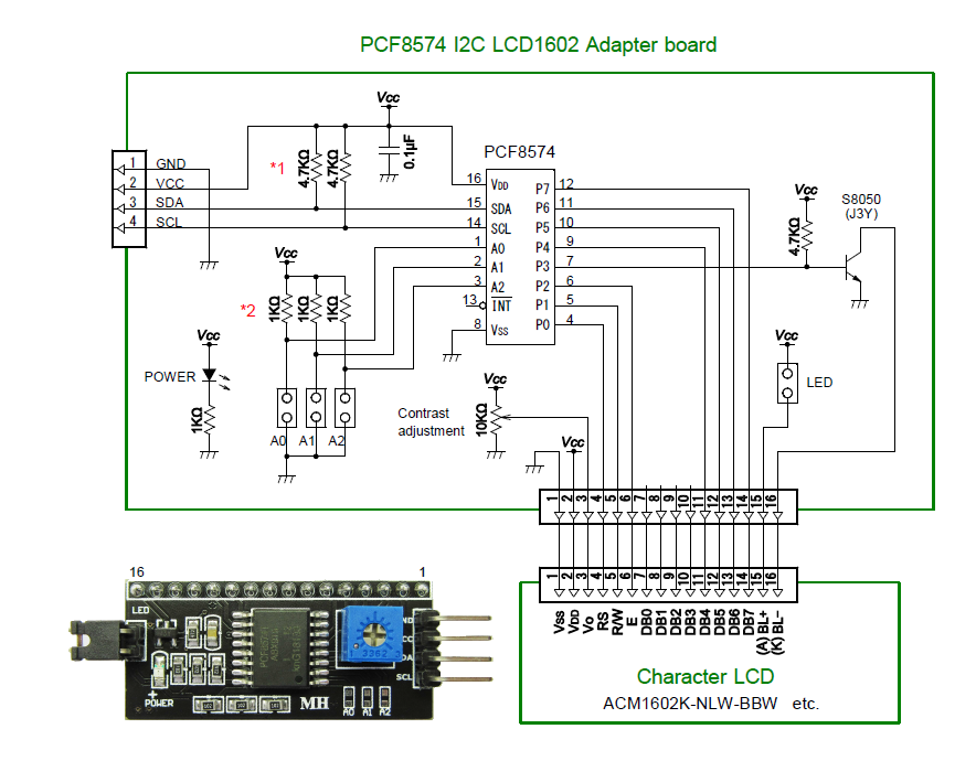
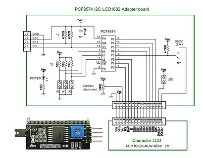
Schaltplan und Foto eines PCF8574 I2C LCD Adapter boards
PCF8574 I2C LCD1602 Adapter board Vcc GND SDA SCL A0 A1 A2 PCF8574 VDD P7 P6 P5 P4 P3 P2 P1 P0 INT S8050 4.7k Vcc Contrast adjustment 10k A0 A1 A2 1k 1k 0.1uF LED Character LCD ACM1602K-NLW-BBW etc. Vss
in „HD44780 I2C Adapter“ · Mikrocontroller und Digitale Elektronik · · Schaltpläne
-
 Bild
Bild
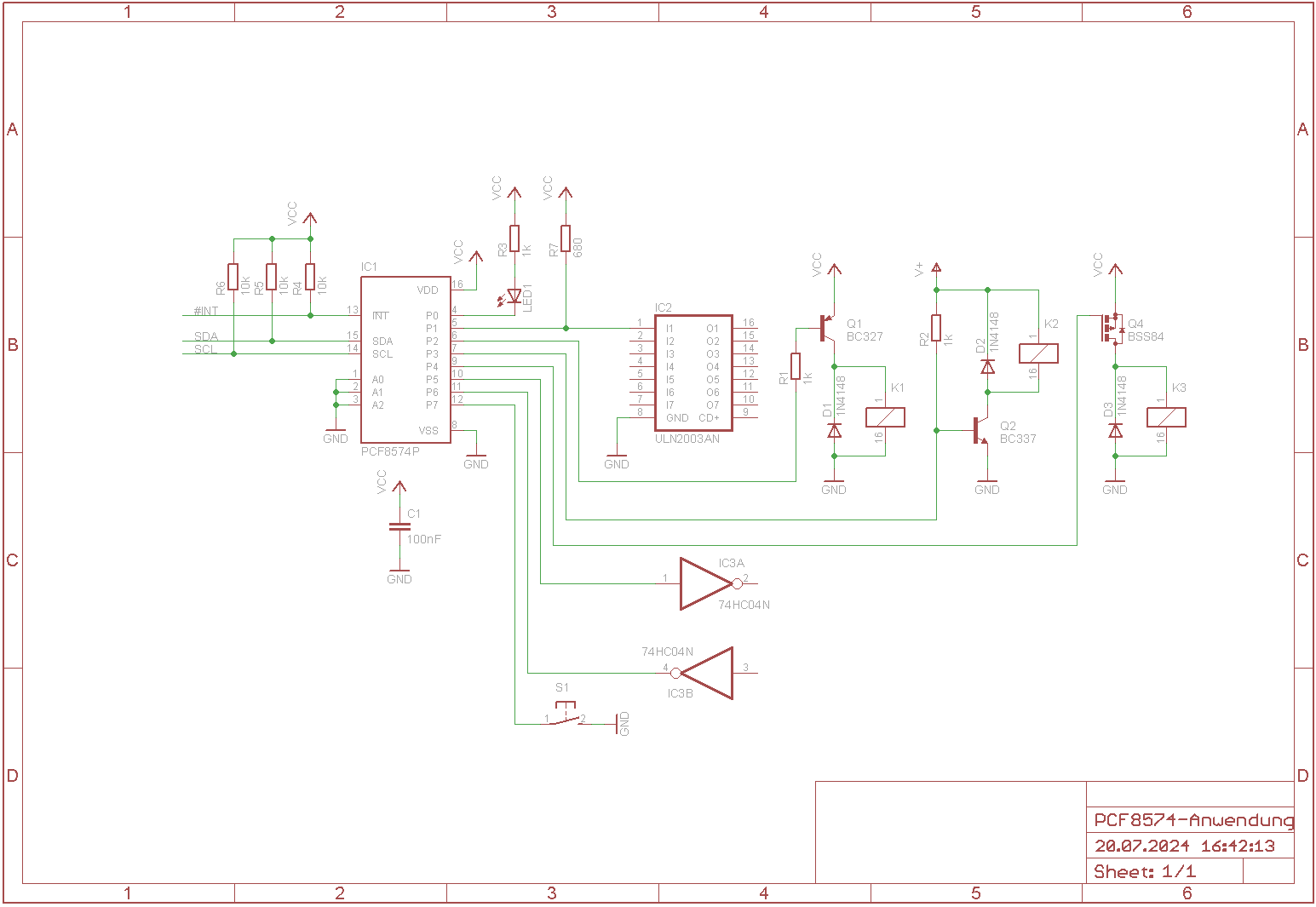
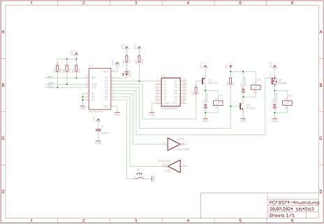
Schaltplan mit PCF8574 und ULN2003AN
VCC, R6, 10k, R5, 20, IC1, PCF8574P, SDA, SCL, A0, A1, A2, VSS, GND, P0 bis P7, R8, 1k, LED1, LED2, IC2, ULN2003AN, VCC, Q1, BC327, R7, D1, IN4148, K1, K2, D2, IN4148, Q4, BSS84, K3, V4, D3, IN4148, Q2, BC337, GND, C1, 100nF, IC3A, 74HC04N, IC3B, S1, PCF8574-Anwendung, 20.07.2024 16:12:13, Sheet: 1/1
in „Lichtsteuerung über i2c - ULN2803A - S12-100“ · Mikrocontroller und Digitale Elektronik · · Schaltpläne
-
 Bild
Bild
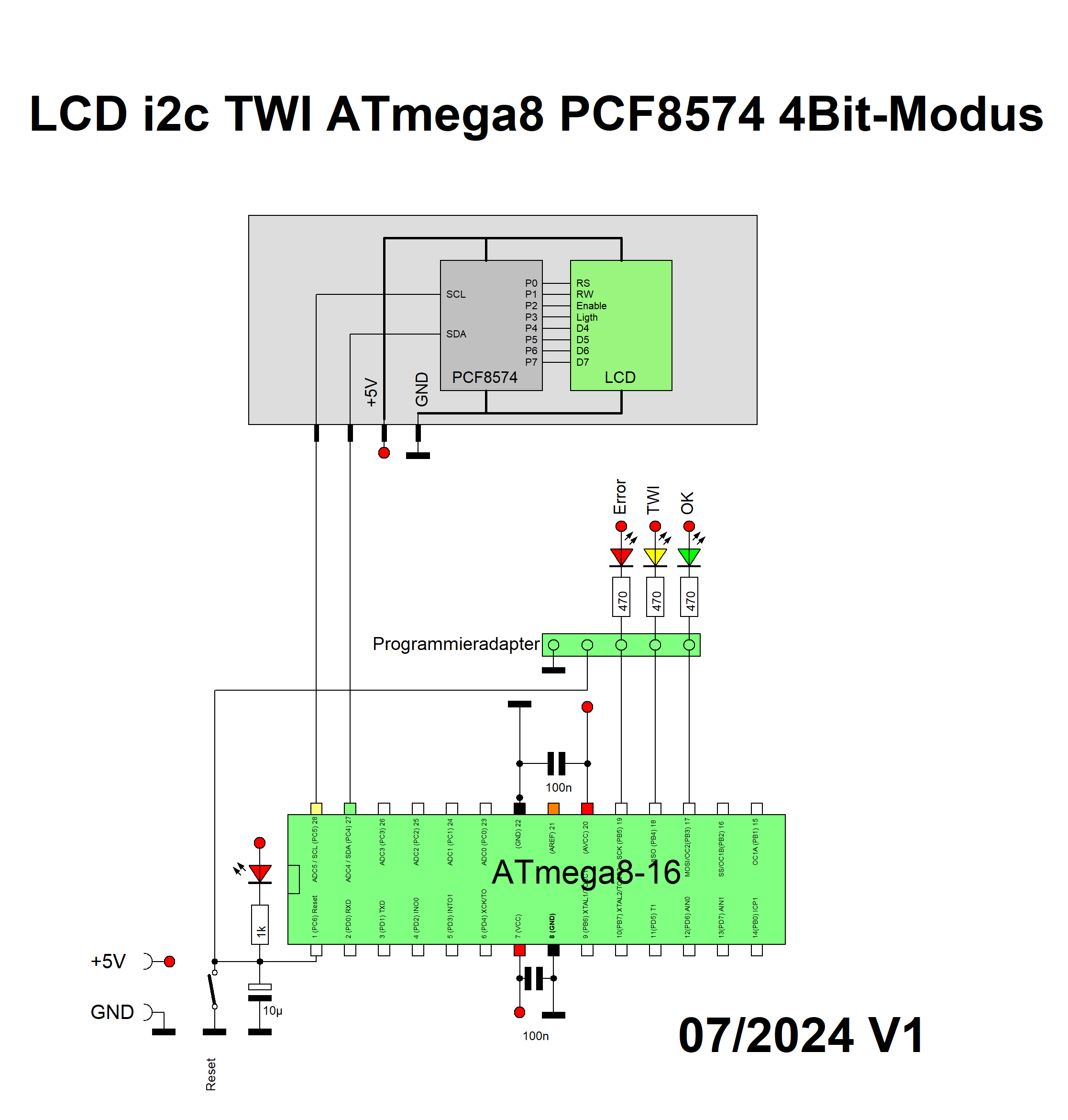
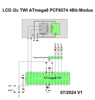
Schaltplan ATmega8 mit PCF8574 und LCD-Ansteuerung
LCD i2c TWI ATmega8 PCF8574 4Bit-Modus P0 RS P1 RW P2 Enable P3 Light P4 D4 P5 D5 P6 D6 P7 D7 SCL SDA +5V GND PCF8574 LCD Error TWI OK 470 470 470 Programmieradapter 100n AD0 A5 I2C SDA P25 AD1 A4 I2C SCL P24 AD2 A3 I2C P23 AD3 A2 I2C P22 AD4 A1 I2C P21 AD5 A0 I2C P20 GND P19 A6 I2C P18 P17 TWI SDA P16 TWI SCL P15 I2C P14 P13 P12 P11 P10 P9 P8 P7 P6 P5 P4 P3 P2 P1 P0 +5V GND 1k 10µ Reset 100n ATmega8-16 07/2024 V1
in „i2c TWI LCD 4Bit PCF8574 HD44780 ATmega8 Assembler“ · Projekte & Code · · Schaltpläne
-
 Bild
Bild
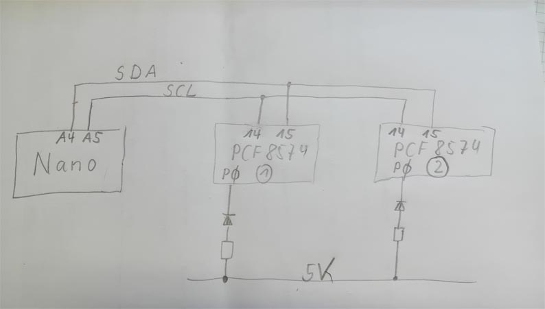
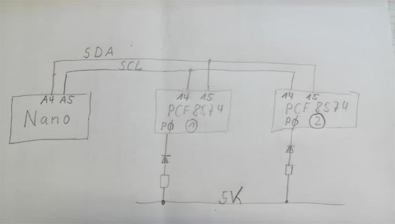
Handgezeichneter Schaltplan mit Arduino Nano und PCF8574
SDA SCL A4 A5 Nano 14 15 PCF8574 P0 1 14 15 PCF8574 P0 2 5K
in „Zwei PCF8574 am Arduino Code Adressierung“ · Mikrocontroller und Digitale Elektronik · · Diagramme
-
 Bild
Bild
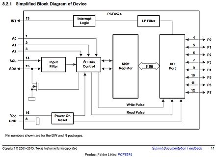
Blockschaltbild des PCF8574 ICs
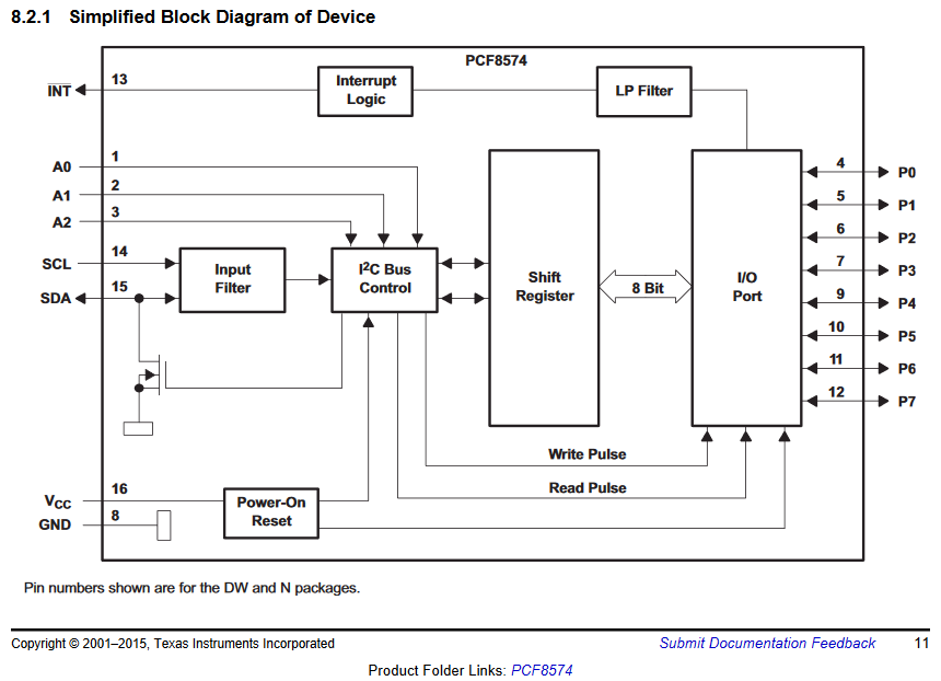
8.2.1 Simplified Block Diagram of Device PCF8574 INT 13 Interrupt Logic LP Filter A0 1 A1 2 A2 3 SCL 14 SDA 15 I2C Bus Control Shift Register 8 Bit I/O Port P0 4 P1 5 P2 6 P3 7 P4 9 P5 10 P6 11 P7 12 VCC 16 GND 8 Power-On Reset Write Pulse Read
in „I2C-Bus: SDA und SCL an ATMEGA328p“ · Mikrocontroller und Digitale Elektronik · · Diagramme
-
 Bild
Bild
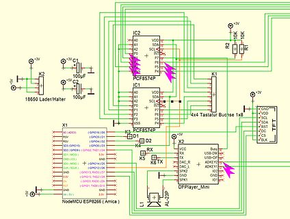
Schaltplan mit NodeMCU ESP8266 und PCF8574 I/O Expander
IC2 PCF8574P A0 A1 A2 P0 P7 P6 P5 VSS VDD SDA SCL +3V R2 10K R1 10K C1 100µF C2 100µF K2 +5V 18650 Lader/Halter K1 K3 PCF8574P D1 D2 K4 RX RX TX TX DAC_R DAC_L SPK2 SPK1 X2 VCC USB-D USB+ GND IO2 GND IO1 K5 K6 TX AL-23P X1 NodeMCU ESP8266 (Amica) A0 (ADC6) GPIO16 D0 RSV GPIO5 D1 RSV GPIO4 D2 SD2 (GPIO9) GPIO2 TXD0 D4 SD1 (MOSI) SDA D3 CLK (SCLK) GPIO12 D5 GND (GPIO13) TXD2 D7 EN (GPIO15) TXD1 D9 GND (GPIO3) RXD0 D6 3.3V RST GND VIN (5V) 3.3V
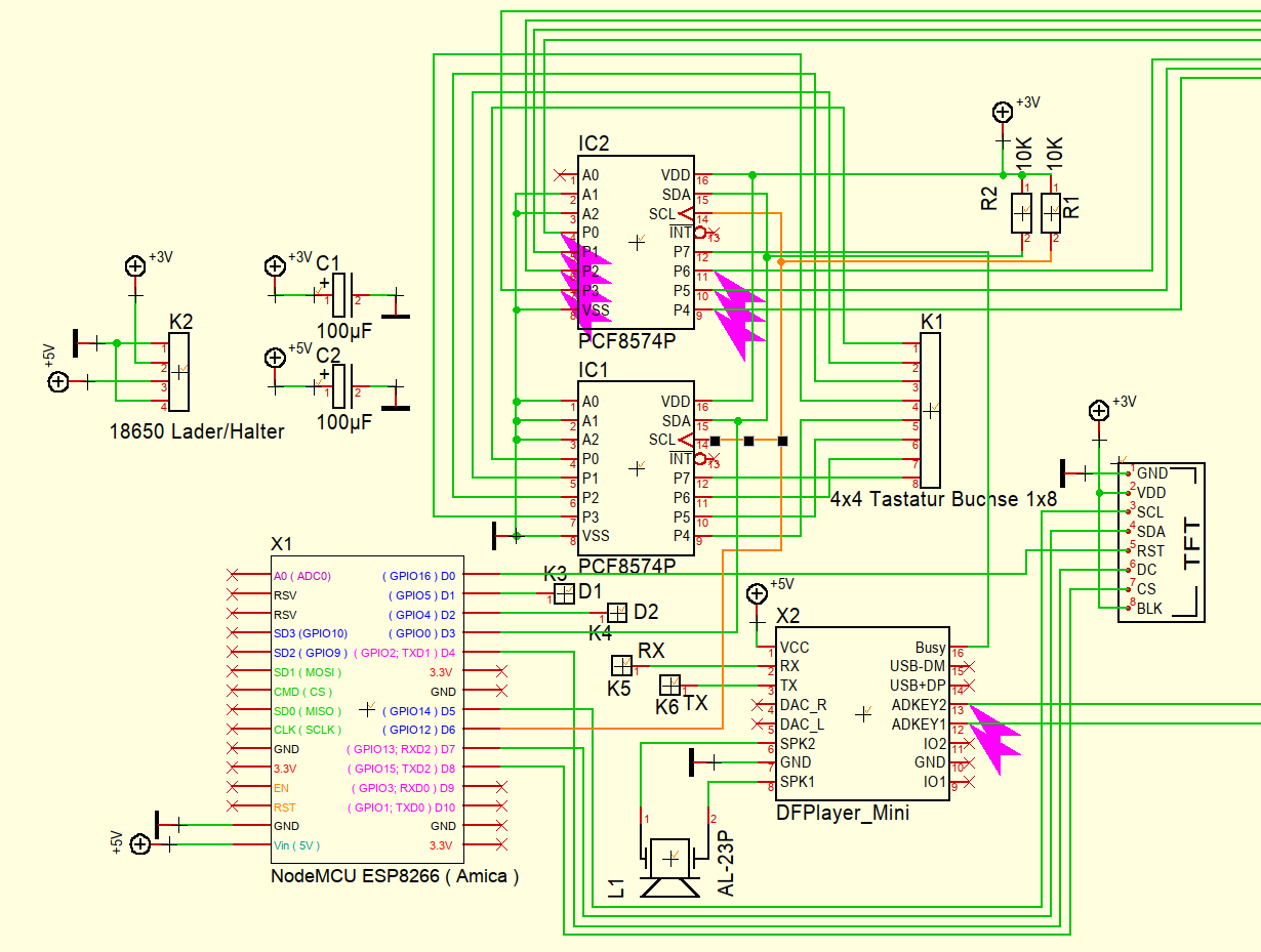
in „ESP8266 mit SPI Display und DF Player“ · Mikrocontroller und Digitale Elektronik · · Schaltpläne
-
Datei
i2c_lcd.h
/* Define PCF8574 slave address */ #define lcd_adr 0x00 // Port expander slave address /* Pin Configuration */ #define lcd_rs PCF1 // LCD RS Pin #define lcd_en PCF3 // LCD enable Pin #define lcd_led PCF0 // LCD back
in „Standart LCD per i2c expander betreiben“ · Mikrocontroller und Digitale Elektronik ·
-
PDF
Spec_Inkontinenzsensor_ATtiny461A.pdf
32 0010 .. + xxx + R/W ATtiny261 analog 8-F 0011 0x18 24 0x30 48 .. + xxx + R/W ATtiny261 binär 8-F PCF8574, Broadcastadress: 0x20 32 0x40 64 0100 .. + xxx + R/W PCF8574 Subadr=000 0x28 40 0x50 80 0101 .. + xxx + R/W MAX127 ATtiny461 0-7 ATtiny461A 0-7 0x30 48 0x60 96 0110 .. + xxx + R/W MAX1236 ATtiny461 8-F ATtiny461A 8-F 0x38 56 0x70 112 0111 .. + xxx + R/W PCF8574A 1000 0x40 64 0x80 128 .. + xxx + R/W 0x48 72 0x90 144 1001 .. + xxx + R/W ATtiny26 analog 0-3, PCF8591, PCF8591, LM75, 0x50 80 0xA0 160 1010 .. + xxx
-
Datei
Angaben.txt
program: TWI (Single) Master Implementation ;*** Function: Implementaion of I2C-Bus with connection to a ;*** 1. I/O-Extension PCF8574 ;*** 2. DSM-0822a ;*** Author: Andreas Hesse ;*** Date of construction: 2003-04-09 ;*** Date of last revision: 2003-11-16 ;*** Version: 1.0.1.0 ;*** Target: AT90Sxxxx (any
in „Crashkurs in Sachen I²C-Bus“ · Mikrocontroller und Digitale Elektronik ·
-
Datei
txlcd_i2c_demo.c
-------------------- txlcd_i2c_demo.c Anbindung eines HS44780 kompatiblen Textdisplays ueber einen PCF8574 I2C I/O Expander MCU : ATtiny44 F_CPU : 8 MHz intern Fuses : fuer 8 MHz intern lo 0xe2 hi 0xdf Fuses : fuer ext. Quarz >= 8 MHz lo 0xde hi 0xdf Pinbelegung I2C --------------- PB0 = SDA PB1 = SCL
in „(sehr) kleines "FrameWork" für ATtiny44“ · Projekte & Code ·
-
Datei
lcd_i2c.c
the I2C-Bus Module. * * The schematics for the display is included as PDF file. * Software assumes a 4x20 Display, connected to I2C by a PCF8574 with Adr. 66. * * (C) 2003 www.Wickenhaeuser.com * */ #include <stdio.h> #include "lcd_io.h" // Re-declare Low level routines as REENTRANT for use in lcd_printf
in „LCD-Ansteuerung mit PCF ?“ · Mikrocontroller und Digitale Elektronik ·
-
Datei
LCD_PCF8574-dotmatrix_7219--learn.asm
/* * LCD_PCF8574_dotmatrix_7219__learn.asm * * Created: 26.11.2014 12:28:23 * Author: Killroymenzel */ .nolist #include "m128adef.inc" .list /************************************************ * Register definition
-
Datei
LCD_TWI.asm
############# TESTPROGRAMM ################################################ ; TWI HARD-ware ATmega8A ; LCD_TWI mit PCF8574 ;######################################################################################### .nolist .include"m8adef.inc" ;Professor wählen .list .equ F_CPU = 8000000 ; Systemtakt
in „RE Bit Display EA DIP204-4 (KS0073)“ · Mikrocontroller und Digitale Elektronik ·
-
PDF
LCD-I2C.pdf
1 2 3 4 5 6 t t n f h g w f e i i o p e L R t t t t t t A B B B B B B A X4 6Pin Tasten 30 - 500 1 2 3 4 5 6 1 D CD4051 470-1050 D A 11 PCF8574 Low 1,5V V 10 B 100 µA * 2000 = 0,2 V C 9 13 X0 14 X1 X 3 15 6 X2 INH 12 X3 1 X4 5 X5 IN7 2 X6 S E IN8 4 X7 S E V
in „Pollin Display HB10401“ · Mikrocontroller und Digitale Elektronik ·