-
PDF
mosfetStufe.pdf
mosfetStufe.pdf
in „MOSFET-Stufe spinnt“ · Analoge Elektronik und Schaltungstechnik ·
-
PDF
Datasheet_MOSFET.pdf
Plastic Tape and This dual SO-8, 60 V, 12.5 mΩ NexFET™ power Package Reel CSD88537NDT 7-Inch Reel 250 MOSFET is designed to serve as a half bridge in low current motor control applications. (1) For all available packages, see the orderable addendum at the end of the data sheet. Top View Absolute Maximum Ratings
in „DRV8711 Steppermotortreiber - Hohe Geschwindigkeiten“ · Analoge Elektronik und Schaltungstechnik ·
-
Bild
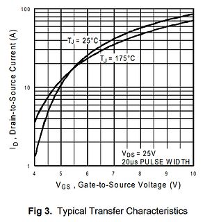
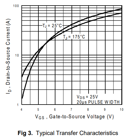
Diagramm der Transferkennlinie eines MOSFETs
100 10 1 ID, Drain-to-Source Current (A) TJ = 25°C TJ = 175°C VDS = 25V 20µs PULSE WIDTH 4 5 6 7 8 9 10 VGS, Gate-to-Source Voltage (V) Fig 3. Typical Transfer Characteristics
in „Lineares Netzteil“ · Analoge Elektronik und Schaltungstechnik · · Diagramme
-
Bild
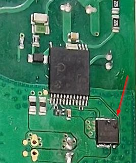
Nahaufnahme einer grünen Leiterplatte mit ICs
MOSFET_defekt.png
in „Fritz Repeater 2400“ · Analoge Elektronik und Schaltungstechnik · · Platinenfotos
-
Bild
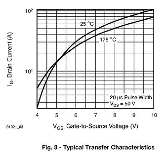
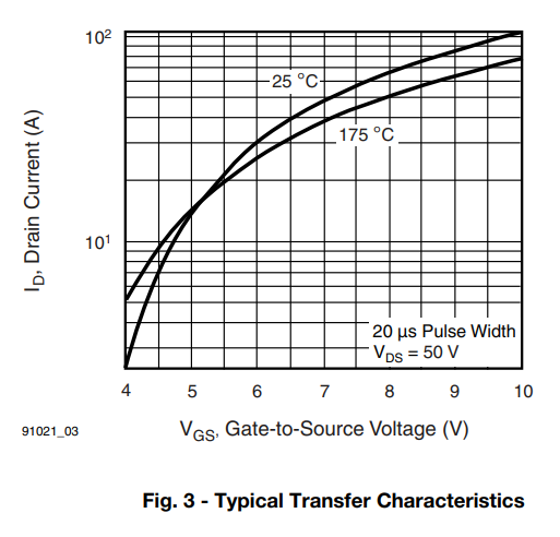
Diagramm der Transferkennlinie eines MOSFETs
10^2 25 °C 10^1 175 °C 20 µs Pulse Width V_DS = 50 V 4 5 6 7 8 9 10 I_D, Drain Current (A) V_GS, Gate-to-Source Voltage (V) 91021_03 Fig. 3 - Typical Transfer Characteristics
in „[Tipp] für Linearbetrieb gut geeigneter MOSFET“ · Analoge Elektronik und Schaltungstechnik · · Screenshots
-
Bild
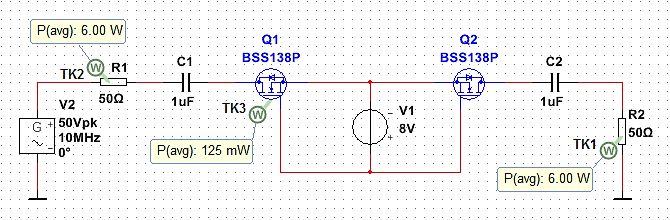
Schaltplan einer elektrischen Schaltung mit MOSFETs
P(avg): 6.00 W TK2 R1 50Ω C1 1uF Q1 BSS138P TK3 P(avg): 125 mW V1 8V Q2 BSS138P C2 1uF R2 50Ω TK1 P(avg): 6.00 W V2 50Vpk 10MHz 0°
in „Technik der HF SPST-Schalter“ · HF, Funk und Felder · · Schaltpläne
-
Bild
Unbekanntes Bauteil oder Konstruktion auf Holzboden
Mosfet_mit_Kuehlkoerper_seitlich.jpg
in „IRF1405PBF Mosfet wird zu heiss und verabschiedet sich“ · Analoge Elektronik und Schaltungstechnik · · Fotos
-
Bild
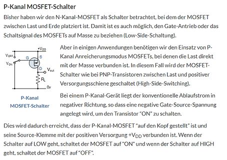
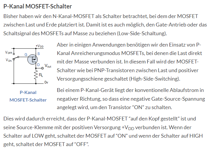
Erklärung P-Kanal MOSFET-Schalter mit Schaltplan
P-Kanal MOSFET-Schalter Bisher haben wir den N-Kanal-MOSFET als Schalter betrachtet, bei dem der MOSFET zwischen Last und Erde platziert ist. Damit es auch möglich, den Gate-Antrieb oder das Schaltsignal des MOSFETs
in „Astabiler Multivibrator mit TLC555 (LMC555)“ · Analoge Elektronik und Schaltungstechnik · · Screenshots
-
Bild
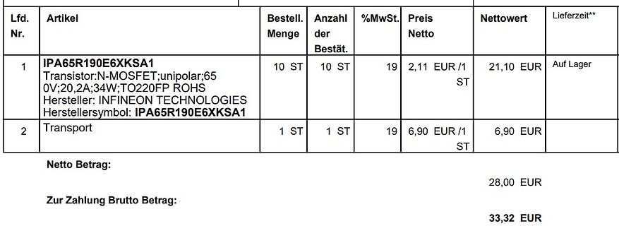
Rechnung für Elektronikbauteile
Lfd. Nr. 1 Artikel IPA65R190E6XKSA1 Transistor:N-MOSFET;unipolar;650V;20,2A;34W;TO220FP ROHS Hersteller: INFINEON TECHNOLOGIES Herstellersymbol: IPA65R190E6XKSA1 Bestell. Menge 10 ST Anzahl der Bestät. 10 ST %MwSt. 19 Preis Netto 2,11 EUR /1 ST Nettowert
in „LG OLED65C97LA lässt sich nicht mehr einschalten“ · Analoge Elektronik und Schaltungstechnik · · Screenshots
-
Bild
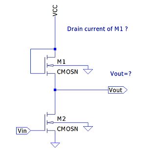
Schaltplan einer CMOS-Inverter-Schaltung
VCC Drain current of M1 ? M1 CMOSN Vout=? Vout M2 CMOSN Vin
in „Schaltung mit 2 N-Kanal Mosfet“ · Analoge Elektronik und Schaltungstechnik · · Schaltpläne
-
Bild
Schaltplan einer MOSFET-Schaltung
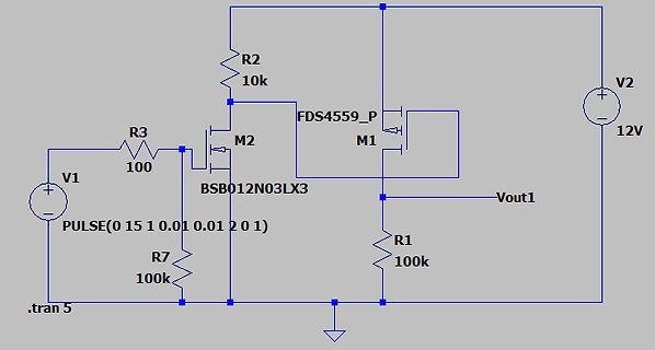
R2 10k M2 FDS4559_P M1 V2 12V R3 100 V1 PULSE(0 15 1 0.01 0.01 2 0 1) BSB012N03LX3 Vout1 R1 100k R7 100k .tran 5
in „Mit 3.3V Logik 12V Logik schalten (Optokoppler vs NPN + MOSFET vs Load Switch vs SSR)“ · Mikrocontroller und Digitale Elektronik · · Schaltpläne
-
Bild
Schaltplan und Kennlinien eines Inverters mit Load-Transistor
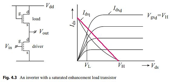
Vdd load d s g Vout Vin g d driver s Fig. 4.3 An inverter with a saturated enhancement load transistor Ids Idsd Vgsd=VH V_L V_H Ids Vds
in „nMOS Inverter“ · Analoge Elektronik und Schaltungstechnik · · Diagramme
-
Bild
Schaltplan einer Transistor- und MOSFET-Schaltung
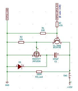
ESP32_GND, ESP32_GPIO_Out, 0 oder 3.3V, R?, 470, R1, 10K, R2, 10k, T1-NPN, BC547B, 1, 2, 3, MOSFET?, IRF530N, 1, 2, 3, C1, 100uF, D1, 1, 2, 100R, R3_Last, SW1, +15V, GND
in „Kondensatorladung über MOSFET gezielt freigeben“ · Analoge Elektronik und Schaltungstechnik · · Schaltpläne
-
Bild
Schaltplan und Oszilloskop-Messkurve einer Highside-Treiberbeschaltung
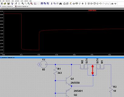
mosdriver-highside.asc mosdriver-highside.raw V(N004,N002) 0.3V -0.3V -0.6V -0.9V -1.2V -1.5V -1.8V -2.1V -2.4V -2.7V -3.0V -3.3V -3.6V 0.0s 0.1s 0.2s 0.3s 0.4s 0.5s 0.6s V2 60 R1 3k3 M2 Si74 Si74 M1 Q1 2N5550 Q2 2N5401 R3 10
in „FET Gatedriver gesucht“ · Analoge Elektronik und Schaltungstechnik · · Screenshots
-
PDF
MOSFET_MaWin.pdf
LSP1 T A L 4 DQ1 c a 0 3 2 IRFP450 R R V 85 8 5 m 4 , 3 , 2 R 0 R 0 1 b 4 . c D LSP2
in „Elektronische Wechselstromsicherung“ · Analoge Elektronik und Schaltungstechnik ·
-
PDF
mosfet_K3673.pdf
2SK3673-01MR 200304 FUJIPOWERMOSFET N-CHANNEL SILICON POWER MOSFET SuperFAP-GSeries Outline Drawings [mm] Features TO-220F High speed switching Low on-resistance No secondary breadown Low driving power Avalanche-proof Applications Switching regulators UPS (Uninterruptible
in „Mosfet K3673 01“ · Analoge Elektronik und Schaltungstechnik ·
-
PDF
Mosfet-Basics-IR.pdf
Drain source and drain and (b) causes a soft breakdown characteristics as shown Figure 5. Trench MOSFET (a) Current Crowding in V-Groove Trench MOSFET, in Figure 7. The leakage (b) Truncated V-Groove MOSFET current flowing between source and drain is denoted by I DSS . There are tradeoffs to be made
in „MOSFET Sättigung“ · Analoge Elektronik und Schaltungstechnik ·
-
PDF
MOSFET-Basics_AN-9010.pdf
July, 2000 AN9010 MOSFET Basics By K.S.Oh CONTENTS 1. History of Power MOSFETs........................................................................................................ 2 2. FETs .............................
in „MOSFET ohne Body-Diode“ · Analoge Elektronik und Schaltungstechnik ·
-
PDF
sihld24_Mosfet.pdf
IRLD024, SiHLD024 Vishay Siliconix Power MOSFET FEATURES PRODUCT SUMMARY • Dynamic dV/dt Rating VDS (V) 60 Available R () V = 5.0 V 0.10 For Automatic Insertion DS(on) GS RoHS* Qg(Max.) (nC) 18 End Stackable COMPLIANT Logic-Level Gate Drive Qgs
in „Mosfet sperrt nicht“ · Analoge Elektronik und Schaltungstechnik ·
-
PDF
Sumo_MOSFET_SOA.pdf
Sumo_MOSFET_SOA.pdf
in „MOSFET Class-A Endstufe, Ruhestrom Einstellung“ · Analoge Elektronik und Schaltungstechnik ·
-
PDF
Sumo_MOSFET_SOA.pdf
Sumo_MOSFET_SOA.pdf
in „MOSFET Class-A Endstufe, Ruhestrom Einstellung“ · Analoge Elektronik und Schaltungstechnik ·
-
PDF
Sumo_MOSFET_SOA.pdf
Sumo_MOSFET_SOA.pdf
in „MOSFET Class-A Endstufe, Ruhestrom Einstellung“ · Analoge Elektronik und Schaltungstechnik ·
-
PDF
Ueberlast_MOSFET_IGBT.pdf
3 Applikationshinweise 3.6.2 Verhalten von IGBT und MOSFET bei Überlast und Kur zschluß Überlast: Prinzipiell unterscheiden sich das Schalt- und Durchlaßverhalten bei Überlast nicht vom „Nor- malbetrieb“ unter Nennbedingungen. Da aufgrund des höheren Laststromes
in „IGBT Linearbetrieb“ · Analoge Elektronik und Schaltungstechnik ·
-
PDF
Mosfet_spice_directive.pdf
in „Mosfet richtig implementieren in Spice : lib“ · Analoge Elektronik und Schaltungstechnik ·
-
PDF
MOSFET_Texas_Instruments.pdf
Description Absolute Maximum Ratings This 40-V, 2.1-mΩ, TO-220 NexFET™ power TA= 25°C VALUE UNIT MOSFET is designed to minimize losses in power VDS Drain-to-Source Voltage 40 V conversion applications. V Gate-to-Source Voltage ±20 V Drain (Pin 2) GS Continuous Drain Current (Package Limited) 110 Continuous
in „Übertragung eines Pspice-Makromodells(OpV) in LTSpice“ · Mikrocontroller und Digitale Elektronik ·
-
PDF
Schaltplan_Mosfet-Unit.pdf
JP1 1 +12V/1 2 +12V/1 +18V +18V GND1 C1 C2 1 1 + N OK1 N G X1-5 Stromversorgung für PowerCap + 8 G 1/63 1 8 100n Q1 Stromversorgung für PowerCap - R5 2 IC1 IRFP2907 X1-4 7 2 X1-3 Stromversorgung für PowerCap - 3 5 MCP1407 4 5 GND HCPL0211 GND JP2 GND1 +12V/2 1 +12V/2 10 x IRFP2907 GND2 2 parallel C3 C4 2 Cap+ 2 + D X2-2 PowerCap + Drain JP4 OK2 D G Stromschiene 1 8 G 1/63 1 8 100n X2-1 PowerCap - CHRG 2 R3 2 IC2 GND WELD 3 7 2 DCHRG 4 3 X1-2 Q2_Gate GND 5 MCP1407 4 5 Ausgang HCPL0211 Q2_Source Gate Stromschiene X1-1 GND GND JP3 GND2 Source +12V/3 1 GND3 2 +12V/3 +12V/2 3 C5 C6 D D + N 2 C7 C8
-
PDF
Berechnung_MOSFET_Verluste.pdf
in „MOSFET´s für H-Brücke, wie viele ?“ · Analoge Elektronik und Schaltungstechnik ·
-
PDF
Berechnung_MOSFET_Verluste.pdf
in „H-Brücke Messungen und Meinung“ · Analoge Elektronik und Schaltungstechnik ·
-
PDF
Mosfet_Verluste_Kuehlkoerper.pdf
Tabelle1 Mosfet IRF3205PbF R ds on @25°C v gs=10V 8 mOhm Fig 4 Normalized On Resistance vs Temperature 2 @160°C R ds on 0,016 Ohm Uf body diode max 1,3 V PWM freq 16 kHz T rise 200 ns 2E-07 s T fall 300 ns 3E-07 s U 24 V duty cycle 0,5 T on 3,125E-05 s T periode 6,25E-05 s T off 3,125E-05 s Anzahl Mosfets (Annahme, dass der Strom „perfekt“ aufgeteilt wird…) - parallel 3 - für Schalt und Leitendverluste 6 - für Body Diodenverluste 3 R th jc 0,75 °C/W T junc max 150°C R th cs 0,5 °C/W T ambient 40°C
in „H-Brücke Messungen und Meinung“ · Analoge Elektronik und Schaltungstechnik ·
-
PDF
Pegelwandler_Mosfet_an97055.pdf
APPLICATION NOTE Bi-directional level shifter for I²C-bus and other systems. AN97055 Philips Semiconductors Bi-directional level shifter for I²C-bus and other Application Note systems. AN97055 Abstract With a single MOS-FET a bi-directional level shifter circuit can be realised to connect devices with different supply voltages of e.g. 5 Volt and 3.3 Volt to one I2C-bus system. The level shifter can also isolate a bus section of powered-down devices from the I2C-bus, allowing the powered part of the I2C-bus to operate in a normal way. The level shifter can also be used in other bus systems or point
in „2x level shift in Reihe“ · Mikrocontroller und Digitale Elektronik ·
-
Bild
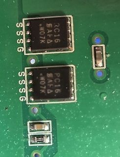
Nahaufnahme von zwei integrierten Schaltkreisen auf Leiterplatte
PC16 SAFA W07K SSG
in „Finde den Mosfet“ · Analoge Elektronik und Schaltungstechnik · · Platinenfotos
-
Bild
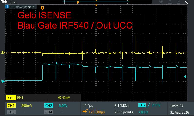
Oszilloskop-Messung von Gate- und Ausgangssignalen
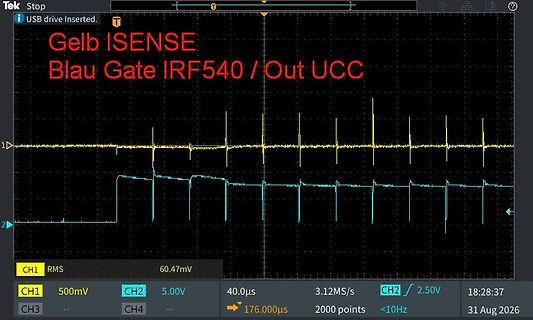
Tek Stop USB drive inserted. Gelb ISENSE Blau Gate IRF540 / Out UCC 1 CH1 RMS 60.47mV 2 50mV CH2 5.0V 40.0µs 3.12MS/s CH2 2.50V 176.0µs 20 points <10Hz 18:28:37 31 Aug 2026
in „Blitzgenerator FA-702B: IRF540 werden sofort heiß – UC3843 / ISENSE auffällig“ · Analoge Elektronik und Schaltungstechnik · · Oszi-Bilder
-
Bild
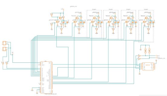
Schaltplan mit Mikrocontroller und MOSFET-Treiberstufen
PMOSFET SMKDSP_1,5/2 PMOSFET SMKDSP_1,5/2 PMOSFET SMKDSP_1,5/2 PMOSFET SMKDSP_1,5/2 PMOSFET AGND MOSFET AGND MOSFET AGND MOSFET AGND MOSFET AGND MOSFET AGND MOSFET AGND MOSFET AGND MOSFET AGND MOSFET AGND MOSFET AGND MOSFET AGND MOSFET AGND MOSFET AGND MOSFET AGND MOSFET AGND MOSFET AGND MOSFET AGND MOSFET AGND MOSFET AGND MOSFET AGND MOSFET AGND MOSFET AGND MOSFET AGND MOSFET AGND MOSFET AGND MOSFET AGND MOSFET AGND MOSFET AGND MOSFET AGND MOSFET AGND MOSFET AGND MOSFET AGND MOSFET AGND MOSFET AGND
in „MOSFET-Eigenleben, LED Treiberschaltung“ · Mikrocontroller und Digitale Elektronik · · Schaltpläne
-
PDF
Linear_Mode_Operation_and_Safe_Operating_Diagram_of_Power-MOSFETs.pdf
the MOSFET is in linear mode operation. Modern power MOSFETS, however, demonstrate dramatically short switching times. State of the art 25V-250V MOSFETs are capable of switching thourgh the linear region within
in „Gleichstromlast MOSFET“ · Analoge Elektronik und Schaltungstechnik ·
-
PDF
Infineon-ApplicationNote_Linear_Mode_Operation_Safe_Operation_Diagram_MOSFETs-AN-v01_00-EN.pdf
the MOSFET is in linear mode operation. Modern power MOSFETS, however, demonstrate dramatically short switching times. State of the art 25V-250V MOSFETs are capable of switching thourgh the saturation region
in „Problem mit N-MOSFET“ · Analoge Elektronik und Schaltungstechnik ·
-
PDF
MOSFET_Gate_Driver_Circuit.pdf
MOSFET Gate Drive Circuit Application Note MOSFET Gate Drive Circuit Description This document describes gate drive circuits for power MOSFETs. © 2017 - 2018 Toshiba Electronic Devices & Storage Corporation
in „MOSFET npn/pnp Driver“ · Analoge Elektronik und Schaltungstechnik ·
-
PDF
MOSFET_Gate_Drive_Circuit_.pdf
MOSFET Gate Drive Circuit Application Note MOSFET Gate Drive Circuit Description This document describes gate drive circuits for power MOSFETs. © 2017 - 2018 Toshiba Electronic Devices & Storage Corporation
in „Gatebeschaltung Treiber“ · Analoge Elektronik und Schaltungstechnik ·
-
PDF
Reverse_Batery_Protection.pdf
MOSFET past this was a blocking point for the use of a p- channel MOSFET because you have to replace The huge benefit by using a p-channel an n-channel MOSFET with a two to three times MOSFET belongs to the
in „Sinn der Dioden in Schaltung (Bild)“ · Analoge Elektronik und Schaltungstechnik ·
-
PDF
Reverse_Battery_Protection.pdf
MOSFET past this was a blocking point for the use of a p- channel MOSFET because you have to replace The huge benefit by using a p-channel an n-channel MOSFET with a two to three times MOSFET belongs to the
in „Schon wieder: Verpolungsschutz-MOSFET und LogicLevel-FET gesucht“ · Analoge Elektronik und Schaltungstechnik ·
-
PDF
AN50005.pdf
the paralleled MOSFETs, it is clear that for ideal operation the current should be shared equally by each MOSFET and this is the simplest metric to quantify how well the MOSFETs perform. However, an equally valid approach
in „N-Canal MOSFET Modul“ · Analoge Elektronik und Schaltungstechnik ·
-
PDF
AutomotiveMOSFETsinLinearApplication-ThermalInstability.pdf
(SOA). 1. Introduction Every power MOSFET is based upon a unit The choice of MOSFETs is important criteria for “cell” design structure. MOSFET geometries are applications that use MOSFETs in linear mode specific to each manufacturer, but the
in „Suche MOSFET mit hohem Rds on“ · Mikrocontroller und Digitale Elektronik ·
-
PDF
AutomotiveMOSFETsinLinearApplication-ThermalInstability.pdf
(SOA). 1. Introduction Every power MOSFET is based upon a unit The choice of MOSFETs is important criteria for “cell” design structure. MOSFET geometries are applications that use MOSFETs in linear mode specific to each manufacturer, but the
in „Linearbetrieb MOSFET gesucht“ · Analoge Elektronik und Schaltungstechnik ·
-
PDF
AutomotiveMOSFETsinLinearApplication-ThermalInstability.pdf
(SOA). 1. Introduction Every power MOSFET is based upon a unit The choice of MOSFETs is important criteria for “cell” design structure. MOSFET geometries are applications that use MOSFETs in linear mode specific to each manufacturer, but the
in „Problem mit N-MOSFET“ · Analoge Elektronik und Schaltungstechnik ·
-
PDF
slac-pub-13410.pdf
” commercial power MOSFET, the power MOSFET and the N-channel attaches to the DE275-102N06A, was also tested using the PCB#1 platform. negative source (Vss- in Figure 1) and controls the turn-off of However, because this MOSFET
in „SiC MOSFET schnell (28 MHz) schalten“ · HF, Funk und Felder ·
-
PDF
Article_Linear_Power_MOSFETs.pdf
focusing and hot spots may not be InpowerMOSFETs,theterm“secondbreakdown”refers self-correcting, which can lead to device failure. toasuddenreductioninaMOSFET’sblocking-voltagecapa- In the linear mode, a power MOSFET is subjected to bilityfollowedbyalossof
in „Stromsenke / el. Last“ · Analoge Elektronik und Schaltungstechnik ·
-
PDF
Linear_Power_MOSFETS_Basic_and_Applications.pdf
Power MOSFET die. This assumption is not always valid, especially for a large die MOSFETs. Firstly, the edge of a MOSFET diesoldered to the mounting tab of a power package has generally lower temperature compared
in „Gleichstromlast MOSFET“ · Analoge Elektronik und Schaltungstechnik ·
-
PDF
MOSFET_Treiber_slup169.pdf
conversion applications. bipolar junction transistors. One of these benefits is the ease of use of the MOSFET devices in high MOSFET TECHNOLOGY frequency switching applications. The MOSFET The bipolar and the MOSFET transistors exploit transistors are simpler to drive because their the same operating principle
in „Igbt über Trafo --> Ansteuerungssignal unsauber“ · Mikrocontroller und Digitale Elektronik ·
-
PDF
macom2011.pdf
28 300 12 45 CW 2 - 175 MRF141 MOSFET 28 150 16 40 CW 2 - 175 MRF173 MOSFET 28 80 11 55 CW 2 - 175 MRF173CQ MOSFET 28 80 11 55 CW 2 - 175 MRF151G MOSFET 50 300 14 50 CW 2 - 175 MRF151 MOSFET 50 150 18 40 CW 2 - 175 MRF148A MOSFET 50 30
-
PDF
IntroDepletionModeMOSFET.pdf
help designers further exploit some of the unique characteristics of these devices. Structure The MOSFET transistor family consists of two main types, these being “depletion- mode” and “enhancement-mode” types. Although MOSFETs can be made in either polarity, N-channel MOSFETs are available in all four
in „Selbstleitende MOSFETS“ · Analoge Elektronik und Schaltungstechnik ·