-
 Bild
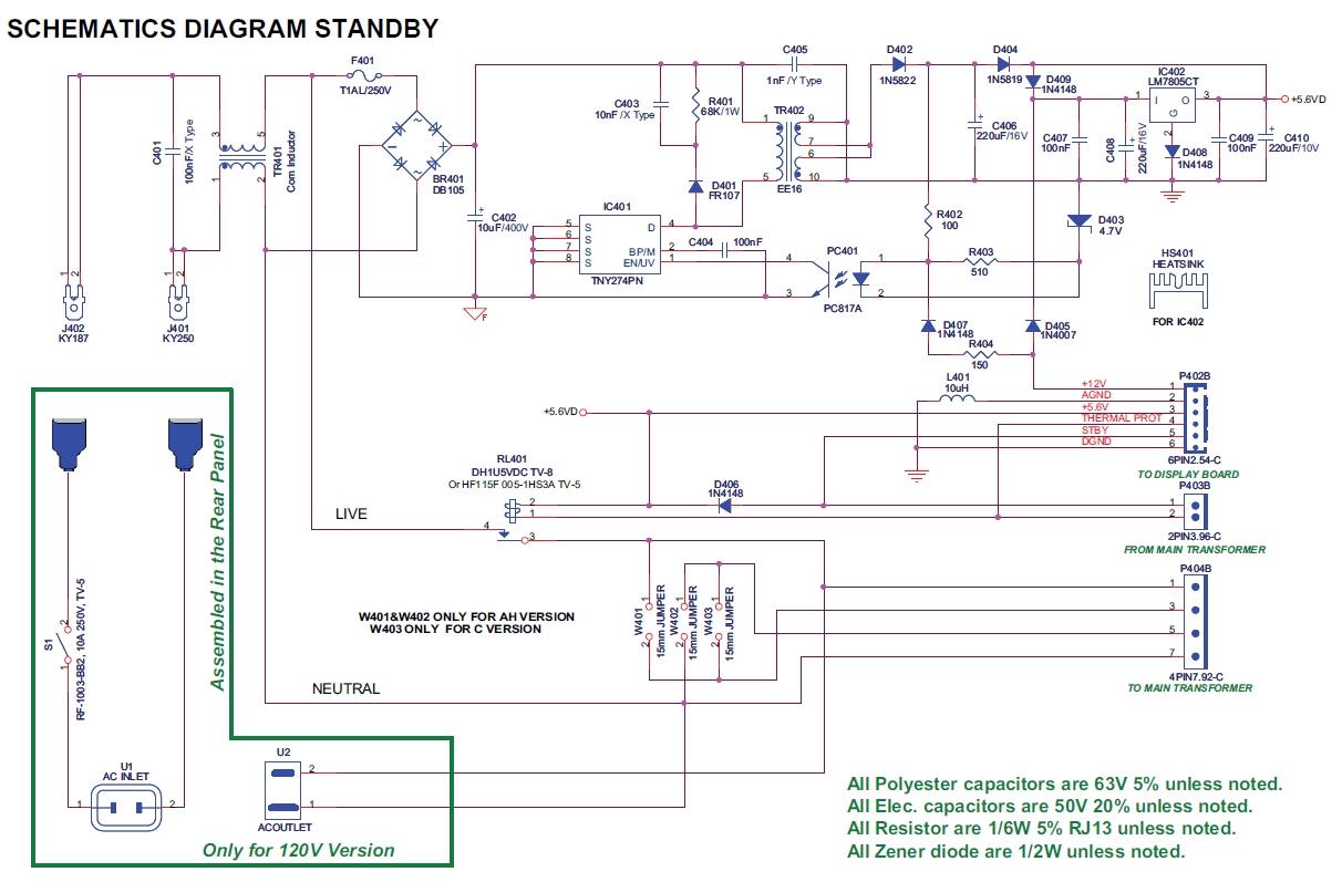
Schaltplan eines Netzteils
39V Vdrv2 : 31V DM852C SK26(SMB) DM852C SK26(SMB) 8T DM851C SK26(SMB) DM856C SK26(SMB) 50V 220uF(Q) 10716 RM857 4.7ROF 3216 RM857 4.7ROF 3216 RM857 4.7ROF 3216 D9038 SK24 D9037 SK24 D9039 N.C 85V Vdrv1 : 67V 16T DM857C MBRF10150CTR DM856C MBRF10150CT 100V 150uF(Q) 12.820 RM851 4.7ROF 3216 RM851 4.7ROF 3216 RM851 4.7ROF 3216 D9034 SK24 D9033 SK24 D9022 SK24 HS805S HS805PI CM84 220uF(M) 10720 RM842 4.7ROF 3216 RM843 4.7ROF 3216 RM841 4.7ROF 3216 RM843 4.7ROF 3216 B13V RS052 2W 4.7R B5V 3T 3T CM81 1000V 33uF 10V 3T 19T
in „Fehlersuche am Netzteil/Backlight BN44-00622B (Samsung LED TV)“ · Analoge Elektronik und Schaltungstechnik · · Schaltpläne
-
PDF
epic.pdf
Pb-free chip specifically designed to provide pyrotechnic Available engineers with a lot of advantages RoHS* • Firing energy down to 50 µJ COMPLIANT • Firing time down to 50 µs • Ohmic range: 2R to 10R • Compatibility with various pyrotechnic composition even Electro-pyrotechnic initiator resistors, also known
in „Zündmechanismus/ Ballongprojekt“ · Analoge Elektronik und Schaltungstechnik ·
-
PDF
epic.pdf
Pb-free chip specifically designed to provide pyrotechnic Available engineers with a lot of advantages RoHS* • Firing energy down to 50 µJ COMPLIANT • Firing time down to 50 µs • Ohmic range: 2R to 10R • Compatibility with various pyrotechnic composition even Electro-pyrotechnic initiator resistors, also known
in „Zünder für Gasgemisch“ · Offtopic ·
-
PDF
AN_MMCA050419.pdf
3.31 MMCA Spec ver 4.0 Name Short Min Max Min Max [nsec] [nsec] [nsec] [nsec] Clock low time tWL * 50 / 10 6.5 Clock high time tWH * 50 / 10 ** 6.5 Clock rise time tTLH * 50 / 10 3 Clock fall time tTHL * 50 / 10 3 Input setup time tISU 3 3 Input hold time tIH 3 3 Output setup time t 5 5 OSU Output hold
in „MMC SD library FAT16 FAT32 read write“ · Projekte & Code ·
-
PDF
SMDJ12A_TVS_Diode.pdf
SMDJ20CA PEV DEV 20.0 22.20 24.50 1 32.4 92.6 2 X SMDJ22CA PEX DEX 22.0 24.40 26.90 1 35.5 84.5 2 X SMDJ22A SMDJ24A SMDJ24CA PEZ DEZ 24.0 26.70 29.50 1 38.9 77.1 2 X SMDJ26A SMDJ26CA PFE DFE 26.0 28.90 31.90 1 42.1 71.3 2 X SMDJ28A SMDJ28CA
in „Frage zu TVS Diode -> Hält sie einen ESD aus?“ · Mikrocontroller und Digitale Elektronik ·
-
Datei
UNO_R4B.txt
(0) PCIROOT(0)#PCI(1400)#USBROOT(0)#USB(7)#USB(7) ACPI(_SB_)#ACPI(PCI0)#ACPI(XHC_)#ACPI(RHUB)#ACPI(HS07)#USBMI(0) ACPI(_SB_)#ACPI(PCI0)#ACPI(XHC_)#ACPI(RHUB)#ACPI(HS07)#USB(7) COM-Port : COM8 (\Device\USBSER000) Child Device 2 : DFU-RT Port Device ID : USB\VID_2341&PID_0069&MI_02\6&FFEEF30&0&0002 Location
in „Arduino UNO R4 in Win10 nicht erkannt“ · Mikrocontroller und Digitale Elektronik ·
-
Datei
UNO_R4D.txt
(0) PCIROOT(0)#PCI(1400)#USBROOT(0)#USB(4)#USB(4) ACPI(_SB_)#ACPI(PCI0)#ACPI(XHC_)#ACPI(RHUB)#ACPI(HS04)#USBMI(0) ACPI(_SB_)#ACPI(PCI0)#ACPI(XHC_)#ACPI(RHUB)#ACPI(HS04)#USB(4) Child Device 2 : DFU-RT Port Device ID : USB\VID_2341&PID_0069&MI_02\6&FFEEF30&0&0002 Location : 0000.0014.0000.004.000.000.000.000.000
in „Arduino UNO R4 in Win10 nicht erkannt“ · Mikrocontroller und Digitale Elektronik ·
-
PDF
msp430fr2532.pdf
CONVERSION COUNTS FOR CONVERSION COUNTS FOR TIME (µs) 0.1-pF TIME (µs) 1-pF CHANGE CHANGE 100 100 25 6 50 8 200 200 50 10 100 16 200 100 50 21 100 31 800 400 200 70 400 112 800 200 200 140 400 202 800 100 200 257 400 333 An alternative measure in sensitivity is the ability to resolve capacitance change over
in „MSP430 Output nur auf zwei von vier Pinnen möglich?“ · Mikrocontroller und Digitale Elektronik ·
-
PDF
trace-elliot-commando-mk-ii-schematics.pdf
4w 220R 72-RM220R 1 R11 Res 1/4w 4K7 72-RM4K7 3 R3 R37 R49 Res 1/4w 47K 72-RM47K 7 R4 R5R9 R43 R47 R50 R54 Res 1/4w 15K 72-RM15K 2 R22 R46 Res 1/4w 2M2 72-RM2M2 2 R51 R53 Res 1/4w 10R 72-RM10R 3 R18 R21 R26 Res 1w 47R metal film 72-RM47R-1WATT 2 R31 R48 Zener diode 15V 72-D-BZX85C15 2 Z1 Z2 Zener diode
in „Reparatur Trace Elliot Commando 15“ · Analoge Elektronik und Schaltungstechnik ·
-
PDF
MA2B150__001.pdf
This product complies with the RoHS Directive (EU 2002/95/EC). Switching Diodes MA2B150 (MA150) , MA2B162 (MA162) Silicon epitaxial planar type For switching circuits ■ Features Unit: mm • Short reverse recoveryrrime t • Small terminal
in „Datenblatt Diode Typ MA150?“ · Analoge Elektronik und Schaltungstechnik ·
-
PDF
2CSR275180R1165-ds201-m-b16-a30.pdf
Bemessungs- 10 kA Betriebskurzschlussaussc haltvermögen, in % von Icu (I ) cs Fehlerstromtyp A Frequenz (f) 50/60 Hz Bemessungsfrequenz (f) 50 … 60 Hz Verlustleistung 3.3 W Einspeisung Beliebig Schaltstellungsanzeige Rot AN / Grün AUS Energiebegrenzungsklass 3 e Elektrische Lebensdauer 10000 Zyklen Mechanische
in „Preiswerte RCBOs (Kombinierte FI/LS)“ · Haus & Smart Home ·
-
PDF
dysr00p401101.pdf
capability. • Compact construction In addition theese displays have very good • High reliability • RoHS compliant viewing angle performance. Combining these features with high reliability and compact Description: construction, makes it an exellent choice for • Multiplexed common anode display digital alphanumeric
in „(V) LED 25-Segment-Display, 6-Digit, CA, DYSR00P401101 (NOS)“ · Markt ·
-
PDF
11000.pdf
D S S S L V E P A A A A P P P P V O O V T E R V P P P P 64 63 62 61 60 59 58 57 56 55 54 53 52 51 50 49 (HS) PE4 1 48 VSS_1 (HS) PE5 47 V 2 DD_1 (HS) PE6 3 46 PA3 (HS) (HS) PE7 4 45 PA2 ei0 PWM3 / PB0 5 44 PA1 PWM2 / PB1 6 43 PA0 ei2 PWM1 / PB2 7 42 PC7 / SS/ AIN15 PWM0 / PB3 8 41 PC6 / SCK / ICCCLK
in „Programmierung von ST72F321Bj9“ · Mikrocontroller und Digitale Elektronik ·
-
PDF
Si2303.pdf
a c o t V i d c 6 e z 1.2 u - a S n m o - ro - 4 n ( 1.0 a ( G D - R G 2 0.8 V 0 0.6 0 1 2 3 4 5 - 50 - 25 0 25 50 75 100 125 150 Q - Total Gate Charge (nC) T - Junction Temperature (°C) g J Gate Charge On-Resistance vs. Junction Temperature Document Number: 72065 www.vishay.com S-80642-Rev. C, 24-Mar
in „Highside-Switch gesucht“ · Analoge Elektronik und Schaltungstechnik ·
-
PDF
Coilcraft_lps6225-270740.pdf
Q200 125°C Core material Ferrite Core and winding loss See www.coilcraft.com/coreloss Environmental RoHS compliant, halogen free Terminations RoHS compliant matte tin over nickel over silver. Other terminations available at additional cost. Weight 309 – 331 mg Ambient temperature –40°C to +125°C with (40
in „Was ist das?“ · Mikrocontroller und Digitale Elektronik ·
-
PDF
ElektronikBauteile.pdf
Bezeichnung ArtNr Preis Preis Kommentar 1 7 WIMA Folienkondensator, Rm 5mm, 100nF MKS-2 100N 0,07 € 0,50 € 2 7 WIMA Folienkondensator, Rm 5mm, 330nF MKS-2 330N 0,17 € 1,19 € 3 50 Montageclip für LED 5mm MONTAGERING 5MM 0,02 € 1,00 € 4 5 DC-Kupplung für Hohlstecker, mit Stift 2,1mm HK 21 0,45 € 2,25 € 5
in „[V] - Elektroniksammlung“ · Markt ·
-
PDF
0900766b8144620c_1_.pdf
O1= Virtual Origin of U 90 V 90 A 80 K T = Time From 10% V A T1 = Virtual Front Tim E 70 P A 60 F 50 T2= Virtual Time to H R O O 50 T Example: For an 8/20 s T N 8 s = T1 = Virtual Fron E 40 C C 30 R 20 s = T 2 Virtual Time E E 10 P 20 P 10 O T 1 TIME 0 T1 -55 50 60 70 80 90 100 110 120 130 140 150 T
in „Hochspannung überprüfen“ · Analoge Elektronik und Schaltungstechnik ·
-
PDF
MAX31855.pdf
) (Note 4) TTHERMOCOUPLE = -50°C to +1768°C, TA= -40°C to +125°C (Note 3) -6 +6 TTHERMOCOUPLE = -50°C to +700°C, T = -20°C to +85°C (Note 3) -2 +2 MAX31855S Thermocouple A Temperature Gain and Offset TTHERMOCOUPLE = +700°C to +1768
in „Thermoelementcontroller MAX31855 conversion time“ · Mikrocontroller und Digitale Elektronik ·
-
PDF
PS-08-50-001.pdf
Terminals Bronze Terminals 18 5.00 7.00 See terminal drawings 20 4.75 6.25 See terminal drawings 22 4.50 5.50 See terminal drawings 24 4.25 5.00 See terminal drawings 26 4.00 4.50 See terminal drawings Note: current ratings are for a single circuit, based on not exceeding 30°C temperature rise MOLEX KK
in „wo bekommt man diesen Steckverbinder - Joint Tech?“ · Mechanik, Gehäuse, Werkzeug ·
-
PDF
RC0802A-TIY-CSV.pdf
Q TY judge using black spot Φ≦0.20 Accept no dense 04 Polarizer specifications, not easy 0.20<Φ≦0.50 3 2.5 bubbles to find, must check in 0.50<Φ≦1.00 2 specify direction. 1.00<Φ 0 Total Q TY 3 Page 14 , Total 23 Pages RC0802A-TIY-CSV NO Item Criterion AQL 05 Scratches Follow NO.3 LCD black spots, white
in „Display Kontrast 2x8“ · Mikrocontroller und Digitale Elektronik ·
-
PDF
IRF540-VIS.PDF
Available R (Ω) V = 10 V 0.077 Repetitive Avalanche Rated DS(on) GS 175 °C Operating Temperature RoHS* Qg(Max.) (nC) 72 COMPLIANT Fast Switching Qgs(nC) 11 Qgd(nC) 32 Ease of Paralleling Simple Drive Requirements Configuration Single Lead (Pb)-free Available D TO-220 DESCRIPTION Third generation Power
in „MOSFET für eine Stromgesteuerte Stromquelle“ · Analoge Elektronik und Schaltungstechnik ·
-
PDF
datasheet-1852825.pdf
Variety of actuator lengths • Instrumentation • Choice of actuation force • Computer products • RoHS compliant and compatible • Industrial B Specification Process s e FUNCTION: Momentary action SOLDERING: Preheating to 100˚C for 45 sec. max. Keep flux flush c CONTACT ARRANGEMENT: SPST, N.O. with top
-
PDF
Datasheet_Video_Decoder_TVP5150AM.pdf
Samples may or may not be available. OBSOLETE: TI has discontinued the production of the device. (2) RoHS: TI defines "RoHS" to mean semiconductor products that are compliant with the current EU RoHS requirements for all 10 RoHS substances, including the requirement that RoHS substance do not exceed 0.1% by weight in homogeneous materials. Where designed to be soldered at high temperatures, "RoHS" products are suitable for use in specified lead-free processes. TI may reference these types of products as "Pb-Free". RoHS Exempt: TI defines "RoHS Exempt" to mean products that contain lead but are
in „TVP5150AM - Datenblatt gibt keine Auskunft über Datenausgabe“ · Mikrocontroller und Digitale Elektronik ·
-
PDF
Unidrive_SP_Manual.pdf
EnDat HIPERFACE and EnDat Ingress Protection IP65 IP65 IP65, IP67, IP68 IP55, IP65 Approvals CE, UL, RoHS CE, UL, RoHS UL, RoHS CE, UL, RoHS Shaft Seals ü ü ü AssembledintheU.S.A. AssembledintheU.S.A. AssembledintheU.S.A. 10 www.controltechniques.com Selecting the Right Motor for the Right Drive Control
in „[V Verkaufe Umrichter Emerson Unidrive SP1403“ · Markt ·
-
PDF
Infineon_TLE4276_DataSheet_v02_81_EN-1381655.pdf
turns off the device at overtemperature. Type Package Marking TLE4276SV PG-TO220-5 4276V TLE4276GV50 PG-TO263-5 4276V50 TLE4276GV PG-TO263-5 4276V TLE4276DV50 PG-TO252-5 4276V50 TLE4276DV PG-TO252-5 4276V Data Sheet 1 Rev.2.81 www.infineon.com/OPTIREG-Linear 2019-05-22 OPTIREG™ Linear TLE4276 LowDropVoltageRegulator
in „Alternative zu TLE4276DVATMA2 von Infineon Spannungsregler von 5 V auf 2,5 V“ · Analoge Elektronik und Schaltungstechnik ·
-
PDF
lm3914.pdf
Samples may or may not be available. OBSOLETE: TI has discontinued the production of the device. (2RoHS: TI defines "RoHS" to mean semiconductor products that are compliant with the current EU RoHS requirements for all 10 RoHS substances, including the requirement that RoHS substance do not exceed 0.1% by weight in homogeneous materials. Where designed to be soldered at high temperatures, "RoHS" products are suitable for use in specified lead-free processes. TI may reference these types of products as "Pb-Free". RoHS Exempt: TI defines "RoHS Exempt" to mean products that contain lead but are
in „Magisches Auge EM80 wiederbeleben ( kein regenerieren )“ · Analoge Elektronik und Schaltungstechnik ·
-
PDF
0141_0315-87_0392_0002_DB-de.pdf
MHz/ °C • Fortschrittlicher spannunggesteuerter Oszillator mit geringem Stromverbrauch Tuning slope 50 MHz/V Abgleichsspannung 0,5-10 V • Geteilter Sende- und Empfangsweg für eine maximale Verstär- kung Übertragungsfrequenz 24000-24250 GHz • Dualer Kanalbetrieb für die Identifikation der Bewegungsrichtung RoHs RoHs 2002/95/EG konform Artikelno. 0392 0002 Anwendungen • Türöffner PIN Belegung • Sicherheitsanwendungen PIN Beschreibung IN/OUT Kommentar • IndustrielleAnwendungen 1 V Eingang Ausgleichsspannung TUNE
in „Distanzmessung mit HB100-Radarmodul?“ · HF, Funk und Felder ·
-
PDF
ZXLD1366.pdf
LEDs 5 LEDs z 400 7 LEDs k ( 11 LEDs Y 350 13 LEDs N 15 LEDs E 300 Q E 250 F N 200 H C 150 I W 100 S 50 0 0 10 20 30 40 50 60 SUPPLY VOLTAGE (V) Switching Frequency, L = 100µH 100 90 80 70 ) ( 60 L C Y 50 Y T 40 1 LED U 3 LEDs D 30 5 LEDs 7 LEDs 20 11 LEDs 10 13 LEDs 15 LEDs 0 0 10 20 30 40 50 60 SUPPLY
in „Spannungsteiler zwischen Arduino und KSQ“ · Mikrocontroller und Digitale Elektronik ·
-
PDF
2097320.pdf
LEDs 5 LEDs z 400 7 LEDs k ( 11 LEDs Y 350 13 LEDs N 15 LEDs E 300 Q E 250 F N 200 H C 150 I W 100 S 50 0 0 10 20 30 40 50 60 SUPPLY VOLTAGE (V) Switching Frequency, L = 100µH 100 90 80 70 ) ( 60 L C Y 50 Y T 40 1 LED U 3 LEDs D 30 5 LEDs 7 LEDs 20 11 LEDs 10 13 LEDs 15 LEDs 0 0 10 20 30 40 50 60 SUPPLY
in „ZXLD1366 Beschaltung ADJ Pin“ · Analoge Elektronik und Schaltungstechnik ·
-
PDF
TBD62783AFG_datasheet_en_20160511.pdf
or upper Input voltage (Output on) IN (ON) 5 VDS = 2.0 V ― ― 2.0 V Supply current VIN= 2.0 V, CC = 50 V (for each channel) ICC 3 Output open ― ― 1.5 mA Clamp diode reverse current IR 6 VR = 50 V, Ta = 85°C ― ― 1.0 μA Clamp diode VF 7 F = 350 mA ― ― 2.0 V forward voltage Turn−on delay tON VCC = 50 V ―
in „Treiber Pendant zu ULN2803“ · Mikrocontroller und Digitale Elektronik ·
-
PDF
ov7620.pdf
Specifications - Rev. 1.2 (7/10/01) OMNIVISION TECHNOLOGIES INC. Register 17 - rw: Horizontal Window start Bits HS7 HS6 HS5 HS4 HS3 HS2 HS1 HS0 Default 0 0 1 0 1 1 1 1 HS<7:0> - selects the starting point of HREF window, each LSB represents four pixels for Inter- laced/Progressive full resolution mode, two pixels
in „wo omnivision kameramodule kaufen“ · Mikrocontroller und Digitale Elektronik ·
-
PDF
IRLR6225PBF_NMOS.pdf
Maximum Safe Operating Area 100 1.1 ) 1.0 Limited By Package ( 80 e a 0.9 A o t V 0.8 e 60 l r h 0.7 I = 50µA C e D i t 0.6 r 40 t D a , , 0.5 ID h 20 ( 0.4 G V 0.3 0 0.2 25 50 75 100 125 150 -75 -50 -25 0 25 50 75 100 125 150 TC , Case Temperature (°C) T J Temperature ( °C ) Fig 9. Maximum Drain Current vs. Fig 10. Threshold Voltage vs. Temperature Case(Bottom)Temperature 10 C ) 1 D = 0.50 C J 0.20 t ( 0.10 e 0.05 n 0.1 p 0.02 e 0.01 R a r0.01 h SINGLE PULSE Notes: T ( THERMAL RESPONSE ) 1. Duty Factor D = t1/t2 2. Peak Tj = P dm x Zthjc + Tc 0.001 1E-006 1E-005 0.0001 0.001 0.01 0.1 t1
in „FET abgeraucht“ · Analoge Elektronik und Schaltungstechnik ·
-
PDF
Power_Resi.pdf
25 - 25 20 0.5 - 9.09K 0.1 - 12.8K 0.05 - 12.8K 0.05 - 47.6K 16.5 RE70N - - - 1.0 - 6.04K RH050 RH-50 - 50 30 0.5 - 73.4K 0.1 - 96K 0.05 - 96K 0.01 - 273K 28 RE75G - - - 0 .10 - 39.2K - 0.5 - 26K 0.1 - 36.7K 0.05 - 36.7K 0.05 - 136K NH050 NH-50 RE75N 50 30 - - - 1.0 - 19.6K 35 - 0.5 - 90K 0.1 - 90K 0.05
in „Logik-Frage zu Leistungswiderständen“ · Analoge Elektronik und Schaltungstechnik ·
-
PDF
TPCA8028-H_datasheet_en_20080122.pdf
VDD −15 V Turn-off time off ⎯ 71 ⎯ Duty ≤ 1%,wt = 10 μs Total gate charge VDD− 24 V, GS= 10 V,DI = 50 A ⎯ 88 ⎯ (gate-source plus gate-drain) Qg VDD− 24 V, GS= 5 V,DI = 50 A ⎯ 46 ⎯ Gate-source charge 1 Qgs1 ⎯ 16 ⎯ nC Gate-drain (“Miller”) charge Q gd VDD− 24 V, GS= 10 V,DI = 50 A ⎯ 12 ⎯ Gate switch charge
in „Ersatz für TPCA8028-H“ · Mikrocontroller und Digitale Elektronik ·
-
PDF
TI_TPS92360_Led_Treiber.pdf
90 90 ) ) ( 80 ( 80 c c n n i c f 70 f 70 E E Vin = 3.0 V 60 60 Vin = 3.6 V Vin = 4.2 V Vin = 5.0 V 50 50 0 10 20 30 40 50 60 70 80 90 100 0 10 20 30 40 50 60 70 80 90 100 Dimming Duty Cycle (%) D003 Dimming Duty Cycle (%) D004 Figure 8-2. Efficiency vs Dimming Duty Cycle 10 LEDs in series Figure 8-3.
in „VIN am Konstantstromtreiber?“ · Analoge Elektronik und Schaltungstechnik ·
-
PDF
1849588.pdf
as follows: CFG_SEL1 = ‘0’, HS_IND is active high, CFG_SEL1 = ‘1’, HS_IND is active low, ‘Asserted’ = Hub is connected at HS ‘Negated’ = Hub is connected at FS CFG_SEL1: The logic state of this pin is internally latched on the rising
in „[V] 2St. 7fach USB2.0 Hub Baustein Microchip/SMCS USB2517-JZX QFN64 (5€)“ · Markt ·
-
PDF
1849588.pdf
as follows: CFG_SEL1 = ‘0’, HS_IND is active high, CFG_SEL1 = ‘1’, HS_IND is active low, ‘Asserted’ = Hub is connected at HS ‘Negated’ = Hub is connected at FS CFG_SEL1: The logic state of this pin is internally latched on the rising
in „[V] 2St. 7fach USB Hub Baustein Microchip/SMCS USB2517-JZX QFN64“ · Markt ·
-
PDF
LITTELFUSE_TVS_DIODE_1_5KE_DATASHEET.pdf
134.5 500 X 1.5KE8.2A 1.5KE8.2CA 7.02 7.79 8.61 10 12.1 125.6 200 X 1.5KE9.1A 1.5KE9.1CA 7.78 8.65 9.50 1 13.4 113.4 50 X 1.5KE10A 1.5KE10CA 8.55 9.50 10.50 1 14.5 104.8 10 X 1.5KE11A 1.5KE11CA 9.40 10.50 11.60 1 15.6 97.4 5 X 1.5KE12A 1.5KE12CA 10.20 11.40 12.60 1 16.7 91.0 5 X 1.5KE13A 1.5KE13CA 11.10
in „230V Schutz mit TVS Diode, Auswahl Diode“ · Analoge Elektronik und Schaltungstechnik ·
-
PDF
p6ke68-2635878.pdf
waveform) (10/1000 µs Strom-Impuls) Very fast response time RS Sehr schnelle Ansprechzeit Compliant to RoHS (exemp. 1a), EEb L Konform zu RoHS (Ausn. 7a), 1 REACH, Conflict Minerals ) E E REACH, Konfliktmineralien ) SPICE Model & STEP File ) 1 Mechanical Data ) 1 Mechanische Daten ) 1 Taped in ammo pack 4000
in „Schaltung für Umpolung Gleichstrommotor“ · Analoge Elektronik und Schaltungstechnik ·
-
PDF
D120561D.PDF
greater than 6 pcs/Laminate.) A B 2006.04.13 Items 1 to 3 were updated. ZHANG XIE 1.) (Page4, Point1) “RoHS” YAN FANG SHENG compliance was added. 2.) (Page8, Table4) Humidity condition was updated. 3.) (Page9, Table5) Number of LED dies was revised from 4 to 2 and forward current of backlight was updated.
in „Probleme mit LCD (MDLS16265BHD)“ · Mikrocontroller und Digitale Elektronik ·
-
 Bild
Schaltplan eines Netzteils
402 10uF/400V B401 DB105 PC401 8P/IN/UV TNY274PN PC817A R402 100 D407 1N414B D405 1N4007 R404 150 HS401 HEATSINK FOR IC402 P402B +5.6V/D AC GND THERMAL POT DGND P403B TO MAIN BOARD 2PN3.96-C FROM MAIN TRANSFORMER P404 1 5 7 4PN7.92-C TO MAIN TRANSFORMER RL401 6D1US/DC TV-8 Or HF15F 005-1HS3A TV-5 D406
in „NAD Verstärker Stby Netzteil Problem“ · Analoge Elektronik und Schaltungstechnik · · Schaltpläne
-
PDF
6861xx14422.pdf
ACTUATOR MATERIAL: PPS A COLOR: BROWN CONTACT MATERIAL: PHOSPOR BRONZE CONTACT PLATING: 100µ TIN OVER 50µ NI QUALITY CLASS: 25 MATING CYCLES ENVIRONNEMENTAL: RECOMMENDED PCB LAYOUT - COMPONENT VIEW OPERATING TEMPERATURE: -25°C UP TO 85°C FLAMABILITY RATING: UL94-V0 COMPLIANCE: LEAD FREE AND ROHS ELECTRICAL
-
Datei
MAX7219.C
/Taster 7-Seg Test auf Pin P1.1 sbit sensor10 = 0x92; //Sensor 10 auf Pin P1.2 //Hilfsbits bit _s, hs, a, b, _sensor10, hsensor10; //Zaehlgroesse 0-4.294.967.295 unsigned long hx; //Feld t1 in dem die Timerwerte abgelegt werden unsigned long t1[10]; //Feldvariable unsigned char x; /*****************
in „MAX 7219 AVR Programm“ · Mikrocontroller und Digitale Elektronik ·
-
PDF
008-0335-0.pdf
for other 741 0.0015 Isolated 10 - 1M .063W 25V options available. 742 0.0037 Isolated 10 - 1M .063W 50V Operating Temperature Range: -55°C to 743 0.0071 Isolated 10 - 1M .100W 100V +125°C. 744 0.0094 Isolated 10 - 1M .125W 200V 745X 0.0058 Bussed 10 - 330K .063W 50V Temperature Coefficient±200 ppm/°C.
in „Widerstandsarray Pitch 0,65mm“ · Analoge Elektronik und Schaltungstechnik ·
-
PDF
Europa_ABCE1102-22_51110-03R_RevD.pdf
Distortion Sine Wave Low Distortion Sine Wave Transfer Time 4 ms. Typical 4 ms. Typical Frequency 50 / 60 Hz. 50 / 60 Hz. BTU/Hr. 239 239 T.H.D. w/100% Resistive Load <4% on Battery <4% on Battery Online Efficiency (w/o Charger) 93% 93% Input Voltage 230 230 Input Current 8.10 Amps 8.10 Amps Output
in „USV - Stromunfall durch Designschwäche“ · Analoge Elektronik und Schaltungstechnik ·
-
PDF
Bourns_221_30.pdf
Pr for R < 2 Ω, 1R00 1 Ω 3001 3.0 KΩ 1.6 x Pr for R ≥ 2 Ω, V < 1.5 x Operating Voltage) ±0.25 % 1R50 1.5 Ω 3301 3.3 KΩ Load Life (2000 hours at rated power) ΔR ±1.0 % 2R00 2 Ω 4001 4.0 KΩ 2R50 2.5 Ω 5001 5.0 KΩ Thermal Shock (-55 ˚C to 155 ˚C, 5 cycles) ΔR ±0.5 % 3R00 3 Ω 7501 7.5 KΩ Resistance to Soldering
-
PDF
VWEW-Fachtagung_2005.pdf
Ausblick und Zusammenfassung VWEW Fachtagung Photovoltaik und Netzintegration Fulda 2005 Topologie mit 50 Hz-Transformator 50 Hz / 60 Hz Transformator AC EMV EMV V VPV Filter Filter AC Vorteile: Sehr zuverlässig, kostengünstig, DC-Stromeinspeisung nicht möglich, Wirkungsgrad bis zu 96 % (für 6 kW Gerät),
in „Trafoloser Wechselrichter-Schaltbild gesucht“ · Mikrocontroller und Digitale Elektronik ·
-
PDF
tsal6100.pdf
= 230 K/W i100 u i 80 R = 230 K/W d 60 r thJA a w 60 r 40 o F - 40 - V I 20 P 20 0 0 0 10 20 30 40 50 60 70 80 90 100 0 10 20 30 40 50 60 70 80 90 100 T - Ambient Temperature (°C) 21212 T - Ambient Temperature (°C) 21211 amb amb Fig. 1 - Power Dissipation Limit vs. Ambient Temperature Fig. 2 - Forward
in „Vorwiderstand LED dimensionieren bei PWM?“ · Mikrocontroller und Digitale Elektronik ·
-
PDF
H8_532-Programmierung.pdf
Figure 17-3 is a memory map. Table 17-3 Socket Adapter Package Socket Adapter 84-Pin PLCC (CP-84) HS538ESC01H 84-Pin windowed LCC (CG-84) HS538ESG01H 80-Pin plastic QFP (FP-80A) HS538ESH01H 297 H8/532 EPROM socket FP-80A CG-84, CP-84 HN27C256 (28 pins) 10 21 RES VPP 1 11 22 NMI EA 9 24 13 25 P30 EO
in „Programmierung Hitachi“ · Markt ·
-
PDF
C535A_WJN_877.pdf
optical grade epoxy offering superior high temperature • Lead-Free and high moisture resistance • RoHS Compliant performance in lighting and illumination applications. B / M O . E R . W W Copyright © 2010 Cree, Inc. All rights reserved. The information in this document is subject to change without notice
in „Vorwiderstände für LED Matrix mit UDN2981“ · Mikrocontroller und Digitale Elektronik ·