-
 Bild
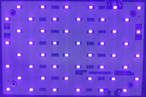
LED-Leiterplatte mit violettem Licht
Layout 12V 2835-LED V3.1 www.urk.de
-
 Bild
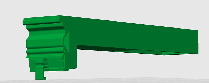
Grünes 3D-Modell eines Profils oder Gehäuseteils
screenshot4.png
-
 Bild
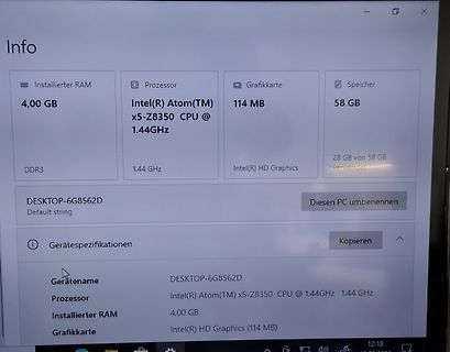
Windows Info-Fenster mit Systemspezifikationen
Info Installierter RAM 4,00 GB DDR3 Prozessor Intel(R) Atom(TM) x5-Z8350 CPU @ 1.44GHz 1.44 GHz Grafikkarte 114 MB Intel(R) HD Graphics Speicher 58 GB 28 GB von 58 GB verwendet DESKTOP-6G8562D Default string Diesen PC umbenennen
-
 Bild
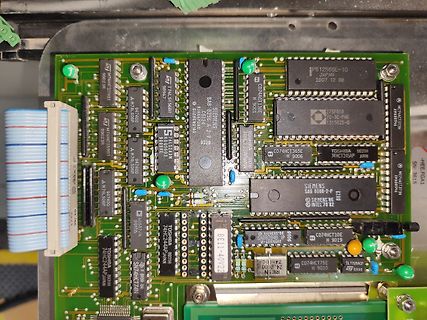
Bestückte grüne Leiterplatte mit verschiedenen integrierten Schaltkreisen
ST M74MC259B1, A 74L506P, ST 74MC259B1, A 74L506P, ST 74L506P, A 74L506P, ST 74L506P, A 74L506P, ST 74L506P, A 74L506P, ST 74L506P, A 74L506P, ST 74L506P, A 74L506P, ST 74L506P, A 74L506P, ST 74L506P, A 74L506P, ST 74L506P, A 74L506P, ST 74L506P, A 74L506P, ST 74L506P, A 74L506P, ST 74L506P, A 74L506P, ST 74L506P, A 74L506P, ST 74L506P, A 74L506P, ST 74L506P, A 74L506P, ST 74L506P, A 74L506P, ST 74L506P, A 74L506P, ST 74L506P, A 74L506P, ST 74L506P, A 74L506P, ST 74L506P, A 74L506P, ST 74L506P, A 74L506P, ST 74L506P, A 74L506P, ST 74L506P, A 74L506P, ST 74L506P, A 74L506P, ST 74L506P, A 74L506P,
-
 Bild
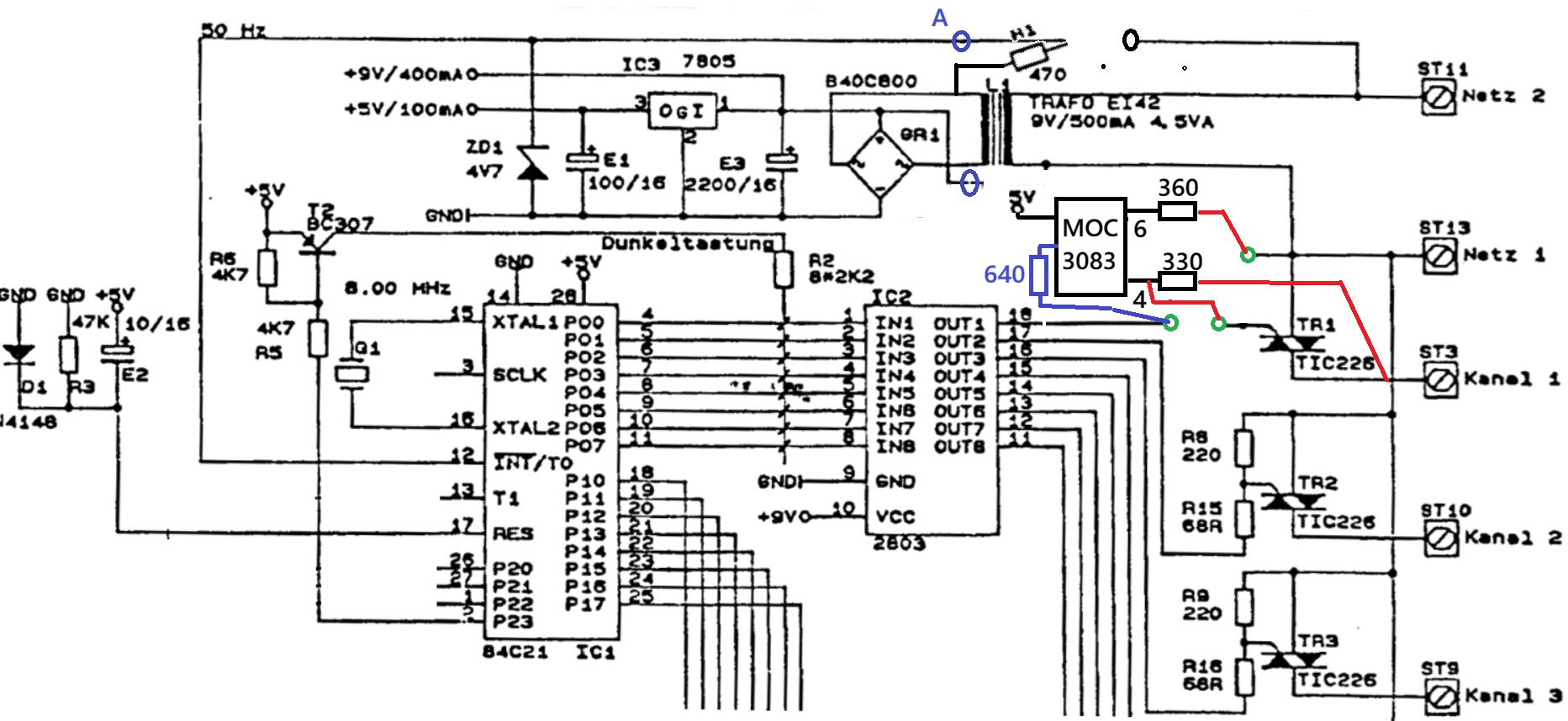
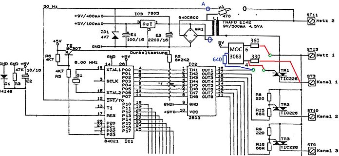
Schaltplan einer Mikrocontroller-Steuerung mit Netzteil
50 Hz, +9V/400mA, IC3 7805, B40C800, TRAFO EI42, 9V/500mA, 4,5VA, ST11, Netz 2, 470, R1, ZD1 4V7, E1 100/16, E3 2200/16, GND, +5V/100mA, BC307, R6 4K7, R5 4K7, Q1, 8.00 MHz, XTAL1, P00, P01, P02, P03, SCLK, P04, XTAL2, P05, P06, P07, IC2 2803, IN1 bis IN8, OUT1
-
 Bild
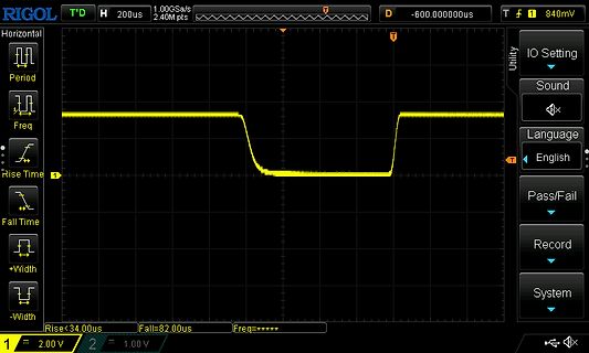
Oszilloskop-Screenshot eines digitalen Signals
RIGOL T'D H 200us 1.00GSa/s T D -600.000000us T 1 840mV Horizontal Period Freq Rise Time Fall Time +Width -Width Utility IO Setting Sound Language English Pass/Fail Record System Rise<34.0us Fall=82.0us Freq=***** 1 = 2.00 V 2 = 1.00 V
-
 Bild
Buchcover Operationsverstärker von Joachim Federau
Joachim Federau Operationsverstärker Lehr- und Arbeitsbuch zu angewandten Grundschaltungen 5. Auflage STUDIUM VIEWEG+ TEUBNER

-
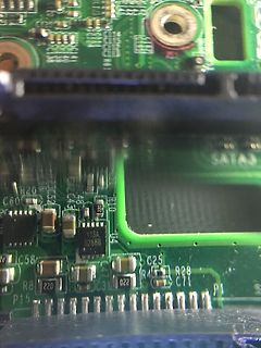
 Bild
Nahaufnahme einer grünen Leiterplatte mit elektronischen Bauteilen
SATA3 C60 H20 C43 R10 Y13A 5288B C58 R8 220 C31 022 C25 R4 C71 R28 P15
-
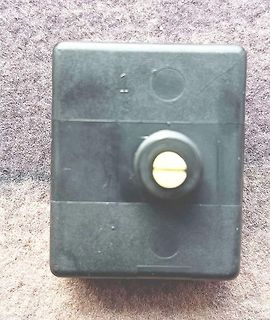
 Bild
Schwarzes Kunststoffgehäuse mit Drehknopf
Schalter_4.jpg
-
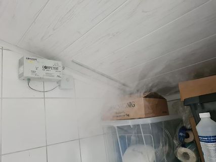
 Bild
Konzept Competent Netzteil an Wand montiert
KONZEPT COMPETENT NIP 2410-1 24V/10A
-
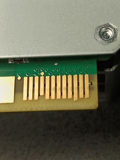
 Bild
Goldkontakte einer Leiterplatte und Gehäuse
Bild_4.jpg
-
 Bild
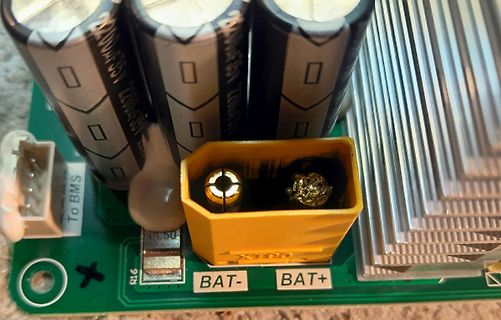
Leiterplatte mit Elektrolytkondensatoren und Batterieanschluss
To BMS, 2200uF 35V, R16, BAT-, BAT+
-
 Bild
-
 Bild
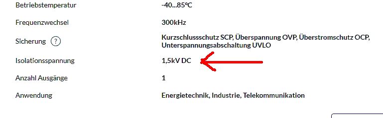
Technische Spezifikationen eines elektronischen Bauteils
Betriebstemperatur -40...85°C Frequenzwechsel 300kHz Sicherung Kurzschlussschutz SCP, Überspannung OVP, Überstromschutz OCP, Unterspannungsabschaltung UVLO Isolationsspannung 1,5kV DC Anzahl Ausgänge 1 Anwendung Energietechnik, Industrie, Telekommunikation
-
 Bild
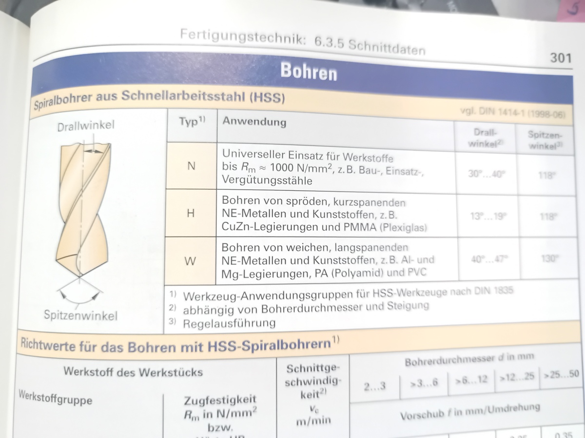
Seite aus einem Fachbuch über Fertigungstechnik
Fertigungstechnik: 6.3.5 Schnittdaten Bohren Spiralbohrer aus Schnellarbeitsstahl (HSS) Drallwinkel Typ Anwendung Drallwinkel Spitzenwinkel N Universeller Einsatz für Werkstoffe bis Rm ≈ 1000 N/mm², z.B. Bau-, Einsatz-, Vergütungsstähle H Bohren von spröden, kurzspanenden NE-Metallen und Kunststoffen, z.B. CuZn-Legierungen und PMMA (Plexiglas) W Bohren von weichen, langspanenden NE-Metallen und Kunststoffen, z.B. Al- und Mg-Legierungen, PA (Polyamid) und PVC 40°...47° 130° Spitzenwinkel Richtwerte für das Bohren mit HSS-Spiralbohrern Werkstoff des Werkstücks Zugfestigkeit Rm in N/mm² bzw. Bohrdurchmesser

-
 Bild
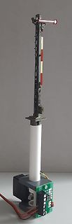
Prototyp eines vertikalen Aufbaus mit LEDs und Steuerung
LED1 LED2 LED3 LED4 LED5 LED6 LED7 LED8
-
 Bild
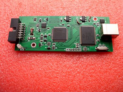
Xilinx FPGA Entwicklungsboard
XILINX Platform Cable USB V2.5 x10133-23 XC9527XL 27715861BA 27715861BA C1, C2, C3, C4, C5, C6, C7, C8, C9, C10, C11, C12, C13, C14, C15, C16, C17, C18, C19, C20, C21, C22, C23, C24, C25, C26, C27, C28, C29, C30, C31, C32, C33, C34, C35, C36, C37, C38, C39, C40, C41, C42, C43, C44, C45
-
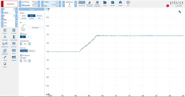
 Bild
Oszilloskop-Messkurve mit Menüoberfläche
Angehalten Oszilloskop 500 µs/div ± 20 V Trigger A 5% Einfach 2 von 4 Auto Instrumente Automatische Einrichtung Standard-konfiguration Öffnen Speichern Drucken Voll Modus Keine Einzel Auto Normal ETS Art Art ändern Quelle B Schwellenwert 4 V Richtung Ansteigend Abfallend Horizontal Pretrigger 30 % 20,0 V 16,0 V 12,0 V 8,0 V 4,0 V 0,0 V -4,0 V -8,0 V -12,0 V -16,0 V -20,0 V -1,5 ms
-
 Bild
-
 Bild
-
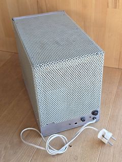
 Bild
Metallgehäuse mit Lochblech und Netzkabel
Imagepipe_4.jpg
-
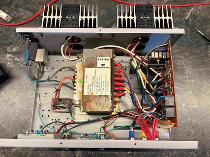
 Bild
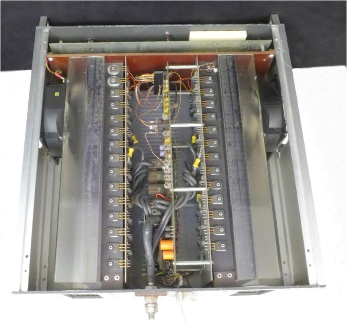
Offenes Schaltnetzteil mit Transformator und Kühlkörpern
TESTED OK a) PRIMARY 230V, 50Hz b) SECONDARY TWO 0.6V-6V, 40 AMP c) SECONDARY THREE 0.6V, 1.5 AMP d) SECONDARY FOUR 0.6V, 0.5 AMP
-
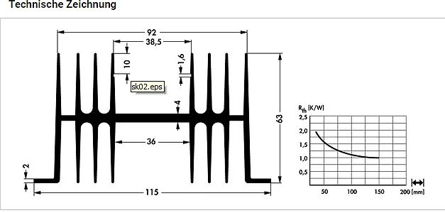
 Bild
Technische Zeichnung eines Kühlkörpers mit Diagramm
Technische Zeichnung 92 38,5 10 1,6 sk02.eps 4 63 36 2 115 Rth [K/W] 2,5 2,0 1,5 1,0 0,5 50 100 150 200 [mm]
-
 Bild
-
 Bild
Typenschild eines Netzteils
220 1A EV22.1 POWER SUPPLY UNIT MODEL LP200/15 SER. No. 9D 149 GWG N3 Inv.-Nr.
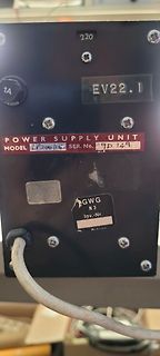
-
 Bild
Nahaufnahme einer Leiterplatte mit Barcode
04431 9 C15 C16 C61 C792 R566 R567 R568 R16 R11 R19 U1 F1 C13 D13 D12 R5 R1 LB5 R13 C23 C22 C5 L2 C4 C3 D1
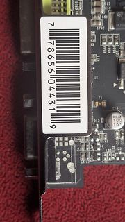
-
 Bild
-
 Bild
Metallgehäuse mit Lochblech und Netzkabel
Imagepipe_4.jpg
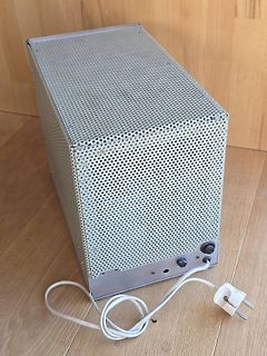
-
 Bild
Drei USB-UART Konverter Leiterplatten
0118311A_Y8_250211 USB-C U21 U22 U23 TP21 TP22 TP23 C21 C22 C23 R21 R22 R23 VDD: 2.25V...5.5V GND RXD TXD UART USB-C VDD: 2.25V...5.5V GND RXD TXD UART VDD: 2.25V...5.5V GND RXD TXD UART
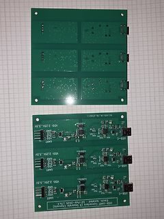
-
 Bild
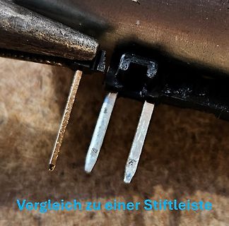
Nahaufnahme von Stiftkontakten eines Steckers
Vergleich zu einer Stiftleiste
-
 Bild
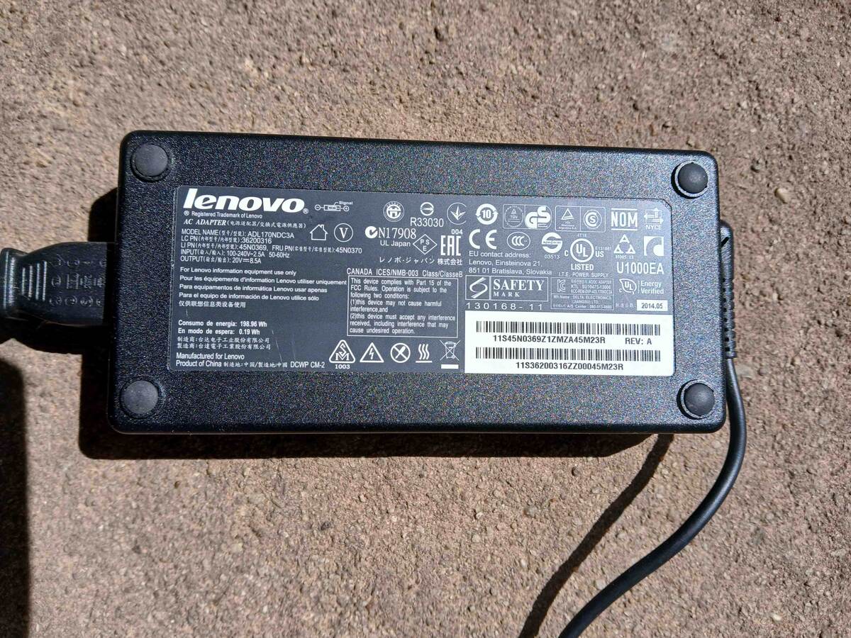
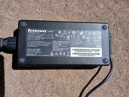
Lenovo Netzteil Typ ADL195NC3A
lenovo AC ADAPTER MODEL NAME: ADL195NC3A INPUT: 100-240V 1.5A OUTPUT: 20V 9.75A CONSUMO de energía: 195.96 W MAX N17908 UL Japan EAC EU contact address: 130168-11 U1000EA Energy verified 2014.05 11S45N0369Z1ZMZA45M23R REV: A 11S36Z00316ZZ0045M23R
-
 Bild
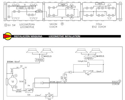
Schaltplan einer Lokomotiv-Installation
LOCOMOTIVE COACH END COACH INSTALACIÓN MÁQUINA LOCOMOTIVE INTALLATION WHEELS CHASIS 1000µF/50V A1 A2 K4 16mm² BROWN 16mm² 24 K4 23 10mm² M 1KW 10mm² BROWN F4 BROWN 25mm² F6 6A FIRST COACH F5 50A 2.5mm² 50A
-
 Bild
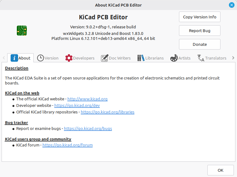
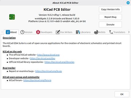
About-Dialog des KiCad PCB Editors
About KiCad PCB Editor Version: 9.0.2+dfsg-1, release build wxWidgets 3.2.8 Unicode and Boost 1.83.0 Platform: Linux 6.12.101+deb13-amd64 x86_64, 64 bit Copy Version Info Report Bug Donate About Version Developers Doc Writers Librarians Artists Translators Description The KiCad EDA Suite is a set of open source applications for the creation of electronic schematics and printed circuit boards. KiCad on the web The official KiCad website - http://www.kicad.org Developer website - https://go.kicad.org/dev Official KiCad library repositories - https://go.kicad.org/libraries Bug tracker Report or examine
-
 Bild
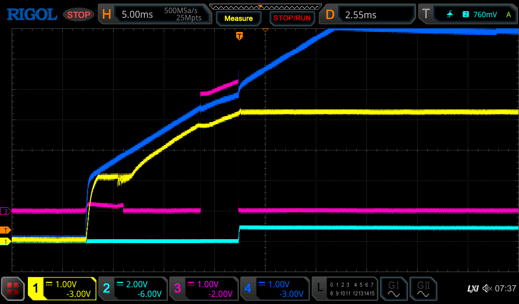
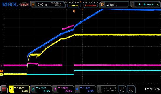
Oszilloskop-Messkurven eines Rigol-Geräts
5.00ms 500MSa/s 25Mpts Measure STOP/RUN D 2.55ms T 760mV A 1 1.00V -3.00V 2 2.00V -6.00V 3 1.00V -2.00V 4 1.00V -3.00V L 0 1 2 3 4 5 6 7 8 9 10 11 12 13 14 15 GI GII LX 07:37
-
 Bild
-
 Bild
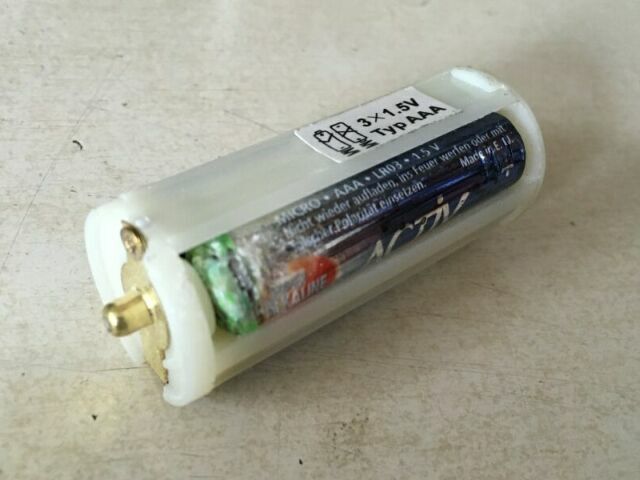
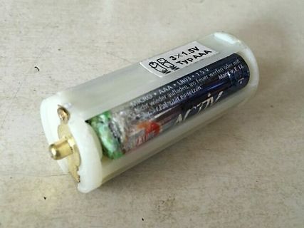
Batteriehalter mit drei AAA-Batterien
3x1.5V Typ AAA MICRO AAA LN03 1.5V Nicht wieder aufladen, ins Feuer oder mit Nicht Polarträger einsetzen. ALKALINE
-
 Bild
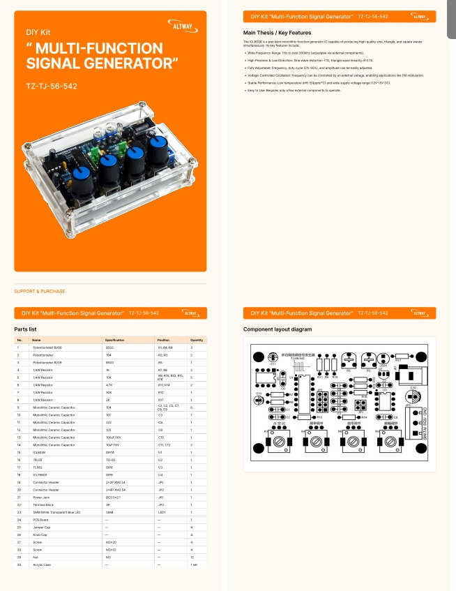
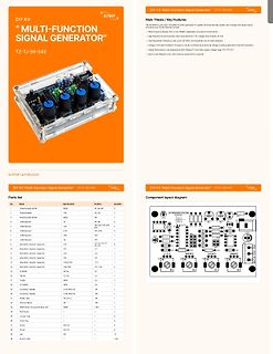
Produktseite eines Multi-Function Signal Generator DIY Kits
Position Quantity 1 Potentiometer RV002 RV,RE 1 2 Potentiometer 104 RV,RE 2 3 Potentiometer RV003 RV,RE 2 4 LED RV004 RV,RE 1 5 LED RV005 RV,RE 1 6 LED RV006 RV,RE 1 7 LED RV007 RV,RE 1 8 LED RV008 RV,RE 1 9 LED RV009 RV,RE 1 10 Ceramic Capacitor 104 C1, C2, C3, C4, C5, C6 6 11 Ceramic Capacitor 222 C7 1 12
-
 Bild
-
 Bild
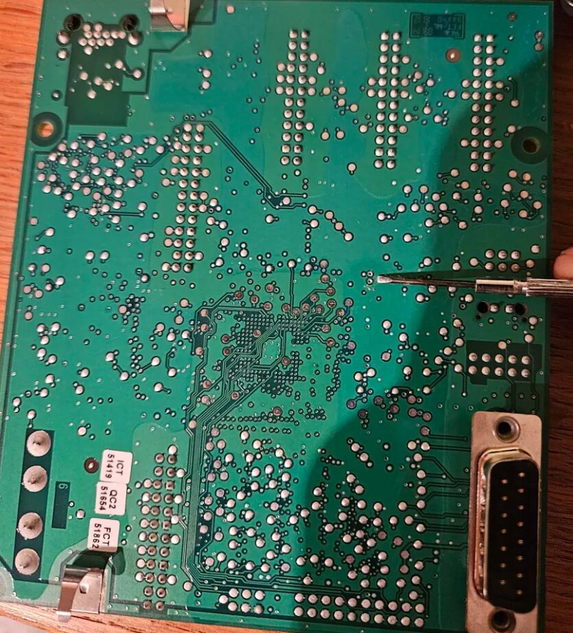
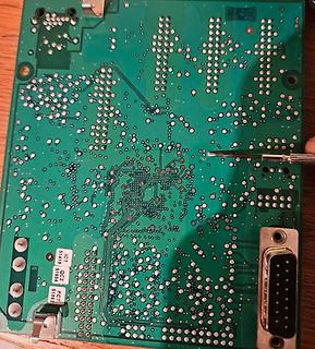
Rückseite einer grünen Leiterplatte mit Lötstellen
ICT QC2 FCT 5149 5164 5162
-
 Bild
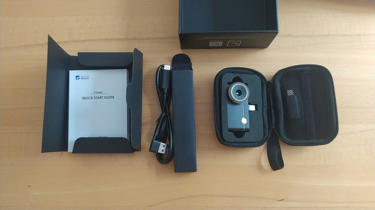
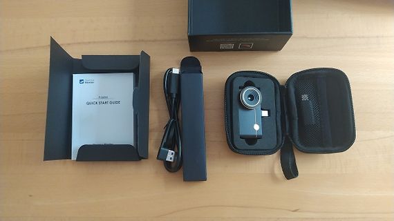
Inhalt einer Thermamaster P-Series Verpackung
Thermamaster P-Series QUICK START GUIDE
-
 Bild
Zahnärztliche Behandlung einer Patientin
Dental__4_.jpg

-
 Bild
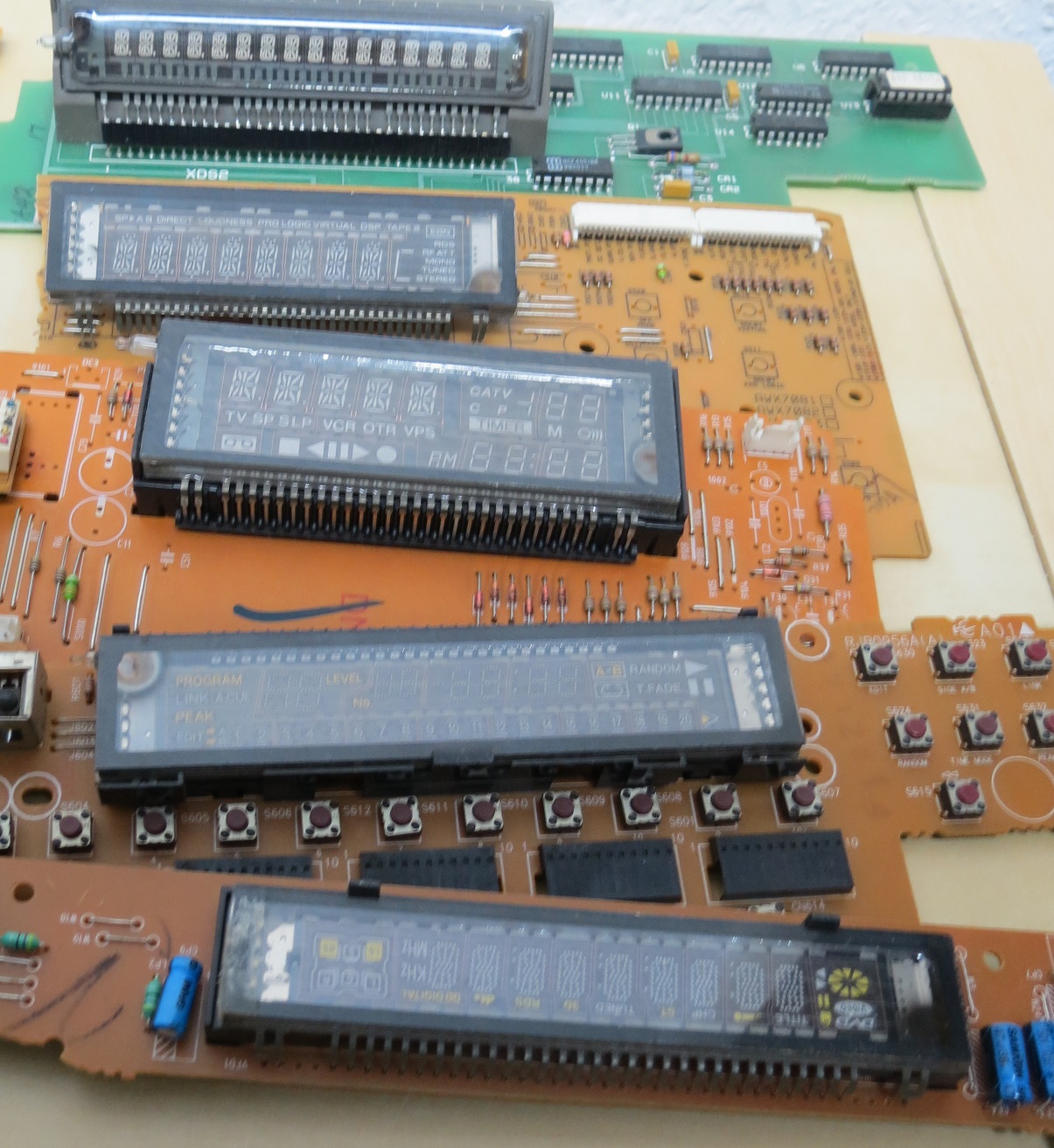
Mehrere Leiterplatten mit LCD-Displays
X062 SPX A 8 DIRECT BUSINESS LOGIC VIRTUAL DSP TAPE 2 CATV TV SP SLP VCR OTR VPS RM PROGRAM LEVEL RANDOM LINK ACQ FADE S605 S606 S612 S611 S609 S607 S601 S604

-
 Bild
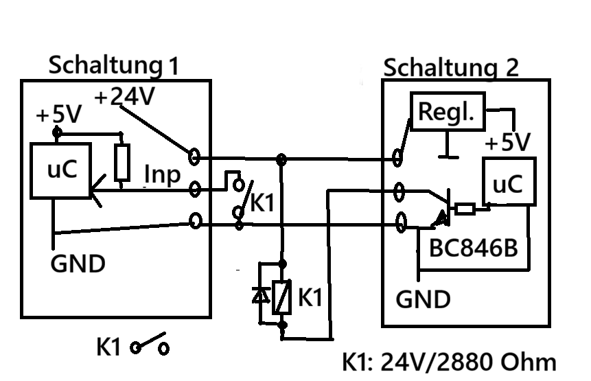
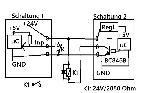
Schaltplan zweier Schaltungen mit Mikrocontroller und Relais
Schaltung 1 +5V +24V uC Inp GND K1 Schaltung 2 Regl. +5V uC BC846B GND K1 K1: 24V/2880 Ohm
-
 Bild
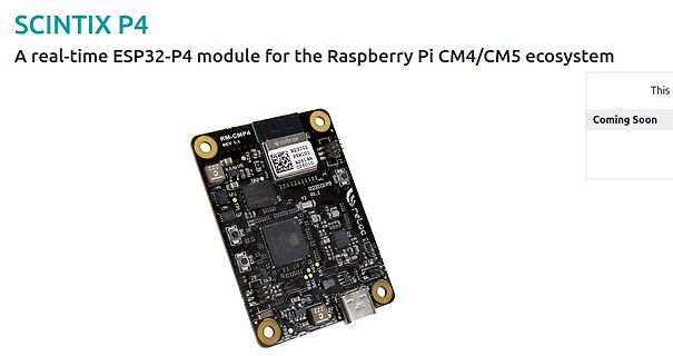
SCINTIX P4 ESP32-P4 Modul für Raspberry Pi
SCINTIX P4 A real-time ESP32-P4 module for the Raspberry Pi CM4/CM5 ecosystem RM-CMP4 REV 1.1 Coming Soon
-
 Bild
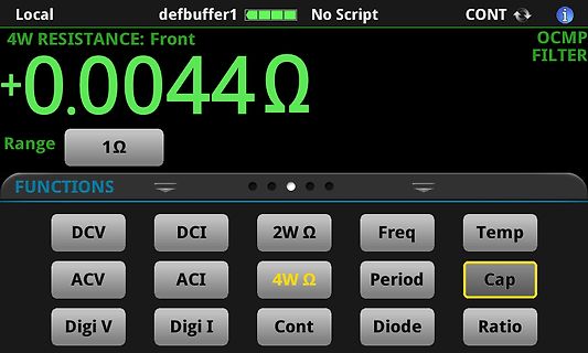
Display eines Multimeters mit Widerstandsmessung
Local defbuffer1 No Script CONT +0.0044Ω 4W RESISTANCE: Front OCMP FILTER Range 1Ω FUNCTIONS DCV DCI 2W Ω Freq Temp ACV ACI 4W Ω Period Cap Digi V Digi I Cont Diode Ratio
-
 Bild
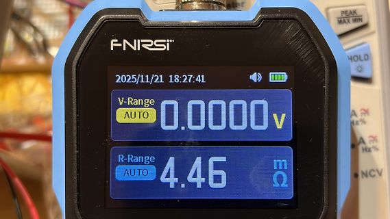
Display eines FNIRSI Multimeters
FNIRSI 2025/11/21 18:27:41 V-Range AUTO 0.0000V R-Range AUTO 4.46 mΩ PEAK MAX MIN HOLD