-
PDF
DEM240128BFYH-LY.PDF
Transflective Positive Mode -20°C ~ +70°C -25°C ~ +75°C l Viewing Direction : 12 o’clock l Driving Scheme : 1/128 Duty, 1/12 Bias l Display Content : 240 x 128 Dots l Power Supply Voltage : 5.0V (typ.) l LCD Driving Voltage (VLCD=V DD ) 0 : 17.0V (typ.) l Back-light Color : Yellow Green (Lightbox) 2. MODULE ARTWORK
in „glcd DEM240128B mit S6B2086X1 Controller (240x128px), wie ansteuern?“ · Mikrocontroller und Digitale Elektronik ·
-
PDF
WM-F1216VG-6FLWcV03.pdf
WM-F1216VG-6FLWc Ver.3 3/35 (1) Electronic Units 1.1 Absolute Maximum Ratings ITEM SYMBOL MIN TYP MAX UNIT NOTE Operating Temperature TOP -20 - +70 ℃ - Storage Temperature TST -30 - +80 ℃ - Input power supply Vcc -0.3 - 4.6 V - Supply voltage for step-up circuit VCi -0.3 - 4.6 V - Input voltage range
in „[V] 2,4GHz Transceiver(CortexM3) Chip-Antenne, Balun.“ · Markt ·
-
PDF
armStoneA8_Hardware_V110_eng.pdf
1x I2C 1x SPI 17x GPIO LCD-interfaces: 1x 18bit LVDS Memory: 256 MByte DDR2 DRAM (optional 512MB) 128 MByte NAND Flash (optional 1 GByte) CPU: Samsung S5PV210 800MHz CPU (optional 1GHz) Operating temperature: 0°C...+70°C (optional -20…+85°C) 3 Block diagram Digital to LVDS LVDS 18 bit (JAE FI-S25S)
in „Handydummy (Attrappe)mit richtigem Display 10Zoll - u.a.Motorola Xoom“ · Mikrocontroller und Digitale Elektronik ·
-
Datei
StoppUhr_1ms.bas
------------------------------------------* ' Gesamten Wert Berechnen Für Timer1 Const _irq_teiler_max = Int((_xtal * _irq_abstand /(1000000000)) + 0.5) ' Prescaler Einstellung für Timer1 bestimmen ' Const _irq_vorteiler -> Einstellmöglichkeiten: 1/8/64/256/1024 #if _irq_teiler_max > &H00FF_FFFF Const _irq_vorteiler = 1024 #elseif _irq_teiler_max > &H003F_FFFF Const _irq_vorteiler = 256 #elseif _irq_teiler_max > &H0007_FFFF Const _irq_vorteiler = 64 #elseif _irq_teiler_max > &H0000_FFFF Const _irq_vorteiler = 8 #else Const _irq_vorteiler = 1
in „Stoppuhr mit Bascom AVR“ · Mikrocontroller und Digitale Elektronik ·
-
PDF
SED1565.pdf
Figure 39 Table 35 (VDD= 4.5 V to 5.5 V, Ta = –40 to 85°C) Rating Item Signal Symbol Condition Min Typ Max Units FR delay time FR tDFR CL = 50 pF — 10 40 ns Table 36 (VDD= 2.7 V to 4.5 V, Ta = –40 to 85°C) Rating Item Signal Symbol Condition Units Min Typ Max FR delay time FR tDFR CL = 50 pF — 20 80 ns Table
in „Pollin 128x64 GLCD : Bild verzerrt“ · Mikrocontroller und Digitale Elektronik ·
-
PDF
BTA16.pdf
CHARACTERISTICS Symbol Test Conditions Quadrant Suffix Unit B IGT VD=12V (DC) R L33 Tj=25⋅C I-II-III MAX 50 mA IV MAX 100 VGT VD=12V (DC) R L33 Tj=25⋅C I-II-III-IVMAX 1.5 V VGD VD=V DRM R L3.3k Tj=125⋅C I-II-III-IV MIN 0.2 V tgt VD=V DRM IG = 500mA Tj=25⋅C I-II-III-IVTYP 2 s dG /dt = 3A/ s IL G =1.2 GT Tj=25⋅C I-III-IV TYP 40 mA II 70 I * I = 500mA gate open Tj=25⋅C MAX 50 mA H T VTM * TM = 22.5A tp= 380 s Tj=25⋅C MAX 1.6 V IDRM VDRM Rated Tj=25⋅C MAX 0.01 mA IRRM VRRM Rated Tj=125⋅C MAX 2 dV/dt * Linear slope up tD V =67%DRM Tj=125⋅C MIN 250 V/ s gate open (dV/dt)
in „9kW schalten“ · Mikrocontroller und Digitale Elektronik ·
-
Datei
adude-log.txt
Memory Detail : Block Poll Page Polled Memory Type Mode Delay Size Indx Paged Size Size #Pages MinW MaxW ReadBack ----------- ---- ----- ----- ---- ------ ------ ---- ------ ----- ----- --------- eeprom 65 6 4 0 no 128 4 0 4000 4500 0xff 0xff Block Poll Page Polled Memory Type Mode Delay Size Indx Paged
in „Pollin Geigerzähler Bericht“ · Mikrocontroller und Digitale Elektronik ·
-
Datei
felermeldung.txt
Size Size #Pages MinW MaxW ReadBack ----------- ---- ----- ----- ---- ------ ------ ---- ------ ----- ----- --------- flash 65 6 32 0 yes 8192 64 128 30000 30000 0xff 0xff Block Poll Page Polled Memory Type Mode Delay Size Indx
in „Fehler beim Flashen des ATtiny85 mit dem Arduino uno“ · Mikrocontroller und Digitale Elektronik ·
-
Datei
i2c-sniffer.c
PIND & I2C_MASK) // how many START / STOP cycles we want to sample before dumping to console #define MAX_SAMPLES 8 // how many samples we want for wire (00 01 10 11) debugging #define MAX_WIRE_SAMPLES 255 // the sample buffer char *b; // determine largest area available uint16_t availableMemory() { int
-
Datei
lcdcon_ft245_4bit320.asm
, YMin-1 ;Adresszähler Reset sbrc Flags, AdresseX rjmp untereha sbr Flags, 1<<AdresseX sbr XStart, 128 sbr XScan, 128 rjmp Mainloop untereha: wdr ;Watchdog Reset cbr Flags, 1<<AdresseX cbr XStart, 128 cbr XScan, 128 sbr Flags, 1<<doFLM ;Markierung für FLM setzen rjmp Mainloop ;***********************
in „LCD Controller für 640x480 LCD mit mega8515“ · Projekte & Code ·
-
PDF
msp430f5529.pdf
USB RAM Sector 7 0023FFh to 001C00h 0023FFh to 001C00h 0023FFh to 001C00h 0023FFh to 001C00h Info A 128 B 128 B 128 B 128 B 0019FFh to 001980h 0019FFh to 001980h 0019FFh to 001980h 0019FFh to 001980h Info B 128 B 128 B 128 B 128 B Information memory 00197Fh to 001900h 00197Fh to 001900h 00197Fh to 001900h 00197Fh to 001900h (flash) 128 B 128 B 128 B 128 B Info C 0018FFh to 001880h 0018FFh to 001880h 0018FFh to 001880h 0018FFh to 001880h 128 B 128 B 128 B 128 B Info D 00187Fh to 001800h 00187Fh to 001800h 00187Fh to 001800h 00187Fh
in „Tastatur komplett selbst erstellen“ · PC Hard- und Software ·
-
Datei
mmc.c
/* MMC Ansteuerung mit Hilfe einer Software SPI (C) 2006 Christian Julius Kartengrösse: 128 MB Blocks 64MB: 0x08.00.00.00 (int32) Aufteilung in 4 x 16 MB = Bank 0 0x00.00.00.00 Bank 1 0x01.00.00.00 usw. max. Blocknummer pro Bank = 0xffff */ // Fehlercodes #define NO_ERROR 0 #define MMC_ERROR
-
Datei
Sperlings_VU_UNO.ino
to count as long press [500] # define N_PIXELS 63 // Number of pixels in each string [18] # define MAX_MILLIAMPS 500 // Maximum current to draw [500] # define BRIGHTNESS 128 int AMBILIGHTBRIGHTNESS = 75; # define COLOR_ORDER GRB // Colour order of LED strip [GRB] # define LED_TYPE WS2812B // LED string
in „Arduino Sketch mittels Kippschalter anders "loopen" lassen“ · Projekte & Code ·
-
PDF
tlv571.pdf
Operation D Image Sensor Processing D Low Power: 12 mW at 3 V and 35 mW at 5 V D Auto Power Down of 1 mA Max DW OR PW PACKAGE (TOP VIEW) D Software Power Down: 10 A Max CS 1 24 NC D Internal OSC WR 2 23 AIN D Hardware Configurable RD 3 22 AV 4 21 DD D DSP and Microcontroller Compatible CLK AGND Parallel Interface
in „EEPROM beschreiben ohne MC“ · Mikrocontroller und Digitale Elektronik ·
-
PDF
_MS-SCCSTR_-210625.pdf
Synonym of the Current Language key. Load Balance Timeout Synonym of the Connection Lifetime key. Max Pool Size The maximum number of connections that are allowed in the pool. Max Pool Size does not impose any restrictions other than those implied or explicitly stated in this section. Examples of such
in „Verbindungsproblem mit STM32 und MS-SQL Server“ · Mikrocontroller und Digitale Elektronik ·
-
Datei
AVRootloader.asm
ATmega1284P ;.include "m128Adef.inc" ; ATmega128A ;.include "m128def.inc" ; ATmega128 ;.include "m161def.inc" ; ATmega161 ;.include "m162def.inc" ; ATmega162 ;.include "m163def.inc" ; ATmega163 ;.include "m164PAdef.inc" ; ATmega164PA
-
Datei
AVRootloader.asm
ATmega1284P ;.include "m128Adef.inc" ; ATmega128A ;.include "m128def.inc" ; ATmega128 ;.include "m161def.inc" ; ATmega161 ;.include "m162def.inc" ; ATmega162 ;.include "m163def.inc" ; ATmega163 ;.include "m164PAdef.inc" ; ATmega164PA
in „Bootloader von Hagen - Port toggeln während des Flashens“ · Mikrocontroller und Digitale Elektronik ·
-
PDF
78f9116.pdf
F 0.9 MIN. 0.035 MIN. G 3.2±0.3 0.126±0.012 H 0.51 MIN. 0.020 MIN. I 4.31 MAX. 0.170 MAX. J 5.08 MAX. 0.200 MAX. K 10.16 (T.P.) 0.400 (T.P.) L 8.6 0.339 M 0.25+0.10 0.010+0.004 –0.05 –0.003 N 0.17 0.007 R 0~15° 0~15° P28C-70-400A-1 34 Preliminary Product Information PD78F9116
-
PDF
MPVD7N65.pdf
Thermal Characteristics Characteristic Symbol Rating Unit Thermal resistance, junction to case Rth(j-c) Max. 4.27 C/W Thermal resistance, junction to ambient Rth(j-a) Max. 62.5 marching-power© Copyright reserved 1/5 Ver1.0 MPVD7N65 Power MOSFET Electrical Characteristics (TC=25C unless otherwise noted) Characteristic Symbol Test Condition Min. Typ. Max. Unit Drain-source breakdown voltage BV I =250uA, V V DSS D GS=0V 650 - - Gate threshold voltage VGS(th) ID=250uA, V DS GS 3 4 5 V Drain-source cut-off current IDSS VDS650V, V =GS - - 1 uA Gate leakage
in „Unbekannte Bauelemente“ · Analoge Elektronik und Schaltungstechnik ·
-
PDF
bq24725.pdf
format listed in Table 4. With 10mΩ sense resistor, the bq24725 provides a charge current range of 128mA to 8.128A, with 64mA step resolution. Sending ChargeCurrent() below 128mA or above 8.128A clears the register and terminates charging. Upon POR, charge current is 0A. A 0.1µF capacitor between SRP
in „[V] 3St TI LiIon Lade/ Batterie-Management Chips: BQ24725RG und BQ24072RG“ · Markt ·
-
Datei
GLCD_s6b33b2_test.bas
255-LCD_WR) 'Bit rücksetzten !!!Achtung Steuerleitungen sind teilweise invertiert #Define LCD_WIDTH 128 #Define LCD_HEIGHT 128 #Define LCD_CHARWIDTH 8 #Define LCD_CHARHEIGHT 8 Const LF = 10 Const CR = 13 CONST PI AS DOUBLE = 3.1415926535897932 printerport = 888 Dim As Double d, messaktl, min,max,count
in „LCD-Modul SAMSUNG UG12D228AA von Pollin“ · Mikrocontroller und Digitale Elektronik ·
-
PDF
LC4104C.pdf
standard PGA-208 package. Absolute Maximum Ratings at V = 0 V SS Parameter Symbol Conditions min typ max Unit Maximum supply voltage VDDmax –0.3 7 V Maximum supply voltage VDDH max –0.3 40 V Maximum supply voltage V max –0.3 +0.3 V SS D0 to D7, LOAD, CP, R/L, TEST, DISP, M, EIO1, EIO2, Input voltage VIN
in „Display von Pollin - Datenblatt - Ansteuerung“ · Mikrocontroller und Digitale Elektronik ·
-
Datei
main.c
Project Calculation ++++++++++++++++++++++++++++++++++++++++++++ Battery characteristic: LiPo - LiPO_V_max >=4,2 V - Lipo_V_min =3,5 V --> to activate battery warning signal --> V_min = 0,928571429% of V_max Reference voltage: Vref = 2,56V --> voltage divider 1:1 Warning threshold: 100 kO:100 kO --> U_R2
in „Attiny85 ADC Eingangswiderstand - wie hoch“ · Mikrocontroller und Digitale Elektronik ·
-
PDF
DEM128064J_SBH-PW-N.pdf
(typ.) z Driver IC : ST7565P (Sitronix) z Interface : SPI, Parallel & Serial z Display Contents : 128 x 64 Dots, COG z Operating Temperature : -20°C to +70°C z Storage Temperature : -30°C to +80°C z Backlight : LED, White, Lightguide, Long-Lifetime z ROHS : Compliant 2. MECHANICALSPECIFICATIONS z Module
-
PDF
Vishay-TFPT.pdf
voltage or P70 x R whichever is less (4)Zero power or zero dissipation is considered as measuring power max. 1 % of rated powe70P (5)Please refer to APPLICATION INFORMATION (6)Power levels are depending on way of mounting and substrates used. Higher power up to 200 mW at 25 °C (P ) can be tolerated on uniform
in „SMD Temperaturfühler an Wetterstation“ · Analoge Elektronik und Schaltungstechnik ·
-
PDF
20240122_Waasner_Katalog.pdf
aus der nachstehenden For details please refer to the following checklist: Bandbreite: min. 10 mm max. 400 mm Strip width: min. 10 mm max. 400 mm Checkliste: Streifenlänge: min. 20 mm max. 3000 mm Strip length: min. 20 mm max. 3000 mm Lochdurchmesser min. 4,5 max. 28 mm Hole diameter: min. 4.5 mm max. 28 mm Bandbreite: min. 10 mm max. 400 mm Strip width: min. 10 mm max. 400 mm AnzahStreifenlänge: enen Lmin. 20 mm ser: max. 3000 mmmax. 3 NumbStrip length: t diamemin. 20 mm max. 3000 mm max. 3 Materialstärke 0,27 / 0,30 / 0,35 / 0,50
in „Was ist aus dem Transduktor geworden?“ · Analoge Elektronik und Schaltungstechnik ·
-
PDF
SP14N01L6ALCZ_Hitachi.pdf
SPECIFICATIONS (1) Part Name SP14N01L6ALCZ (2) Outer Dimensions 159.4(W)mm x 101.0(H)mm x 11.0(D)mm(max.) (3) Viewing Area 123 mm min. x 68 mm min. (4) Dot Size 0.48(W)min. x 0.48(H)min. (5) Dot Pitch 0.50(W)mm x 0.50(H)mm (6) Dot Number (Resolution) 240 (W) x 128 (H) (7) Duty Ratio 1/128 (8) LCD Type
in „[V] 1St. Hitach LCD SP14N01L6ALCZ 240x128 Pix mit CFL Converter“ · Markt ·
-
PDF
AVR-ASM-Tutorial_16_05_08_v2.pdf
Potentiometer 10k • 1 HD44780-kompatibles LCD, z.B. 4x20 oder 2x16 Zeichen Teil 6 (Der UART) • 1 Pegelwandler MAX232, MAX232Aoder MAX202 • 5 Kondensatoren • Bei einem MAX232: je 1µF Elektrolytkondensator • Bei einem MAX202 oder MAX232A: je 100nF Keramik- oder Elektrolytkondensator Die Kondensatoren dürfen auch grösser sein. Ist man sich nicht sicher, welchen MAX232 man hat (Aoder nichtA), dann die grösseren Kondensatoren 1µF nehmen, die funktionieren auch beim MAX232Aoder MAX202. • 1 9-polige SUBD-Buchse (female) • 1 dazu passendes Modem(nicht Nullmodem!)-Kabel
in „AVR-ASM-Tutorial: PDF 16.5.08“ · www.mikrocontroller.net ·
-
PDF
Hausbus_for_everyone.pdf
Twisted Pair Leidtungen sind nicht vorgeschrieben, aber sie senken die Störanfälligkeit, erhöhen die max. Übertragungsgeschwindigkeit und erweitern die max. Buslänge. Zusätzlich benötigt man noch zwei Leitungen zur Stromversorgung. Ich würd 18 Volt bzw. 13,8 Volt empfehlen. Jeder knoten hat zwei Stecker und somit Läuft der Bus direkt über die Platine des Kotens. Stromversorgung Knoten MAX485 und uC Laufen mit +5 Volt. Spannungswandler Hardware BUS Sniffer Um den Bus debuggen und überprüfen zu können wird ein Hardware Sniffer benötige. Dieser wird wie ein Knoten am Bus installiert. MAX485
-
Datei
ks108.c
io.h> #include <util/delay.h> #include "mydefs.h" #include "ks108.h" extern volatile char lcd_puffer[128][8]; //################################################################################### // E ist die Bremse des Displays. Braucht ganz schön lange Delays. // Geniale Angaben zum Timing im Datenblatt
in „Kommazahl auf Display anzeigen“ · Mikrocontroller und Digitale Elektronik ·
-
PDF
Metrz_Anschlussdose.pdf
Schnittstelle 1 8 Anzahl Positionen/Kontakte Schnittstelle 2 8P/8C Anschlusswerte, eindrähtig (min. - max.) Leiterquerschnitt, eindrähtig (Kupfer blank) AWG 26/1 - AWG 22/1 Leiterquerschnitt, eindrähtig (Kupfer blank) 0,128 mm² - 0,324 mm² Leiterdurchmesser, eindrähtig (Kupfer blank) 0,409 mm - 0,643 mm
-
Datei
GccAtmega8515_MAX7219_quad.c
<<DDB3)|(1<<DDB4)|(1<<DDB5)|(1<<DDB7); /* SPI einschalten, SPI Master aktivieren, Frequenz auf FCK/128 */ SPCR = (1<<SPE)|(1<<MSTR)|(1<<SPR0)|(1<<SPR1); } void SPI4_Transmit(char addr1, char data1, char addr2, char data2, char addr3, char data3, char addr4, char data4) { PORTB &= ~(1 << PB3); // LOAD
in „ATMEGA8515_SPI ->4-fach MAX7219 instabil, Fragen dazu“ · Mikrocontroller und Digitale Elektronik ·
-
PDF
lv_25-600.pdf
nominal RMS current 10 mA R Measuring resistance R R ● Insulating plastic SaseRMecognized M M min M max according to UL 94-V0 with ±12 V @ ±600 V max 30 200 Ω UC @ ±900 V max 30 100 Ω ● Primary resistor and transducer mounted on printed circuit board with ±15 V @ ±600 V max 100 320 Ω @ ±900 V max 100 180 Ω 128 × 60 mm. I Secondary nominal RMS current 25 mA S N Advantages N /N Turns ratio 600 V : 25 mA P S U C Supply voltage (±5 %) ±12 ... 15 V ● Excellent accuracy IC Current consumption 10 (@ ±15 V ) + S
in „Spannungsregelung Für Gleichtrommaschine“ · Analoge Elektronik und Schaltungstechnik ·
-
PDF
sed1335f.pdf
. a time. However, if a wider range of characters is Built–in CG ROM (160 characters, 5 × 7 pixels max.) CG RAM n CG RAM 2 CG RAM SAG CG RAM 1 M0 = 1 (64 characters max, 8 × 16 pixels max) Basic CG space (256 characters, 8 × 16 pixels max.) 256 characters max. CG RAM M1 = 0 CG ROM M0 = 1 Built-in CG ROM 256 characters max. (160 characters, M1 = 0 5 × 7 pixels max.) CG RAM n CG RAM 2 CG RAM CG ROM ADR CG RAM 1 (64 characters max, 8 × 16 pixels max) Note that there can be no more than 64 characters per bank. Figure 64.
in „SP14Q002-A1 aus eBay - Erfahrungsaustausch“ · Mikrocontroller und Digitale Elektronik ·
-
PDF
SED1330.pdf
. a time. However, if a wider range of characters is Built–in CG ROM (160 characters, 5 × 7 pixels max.) CG RAM n CG RAM 2 CG RAM SAG CG RAM 1 M0 = 1 (64 characters max, 8 × 16 pixels max) Basic CG space (256 characters, 8 × 16 pixels max.) 256 characters max. CG RAM M1 = 0 CG ROM M0 = 1 Built-in CG ROM 256 characters max. (160 characters, M1 = 0 5 × 7 pixels max.) CG RAM n CG RAM 2 CG RAM CG ROM ADR CG RAM 1 (64 characters max, 8 × 16 pixels max) Note that there can be no more than 64 characters per bank. Figure 64.
in „Hilfe ! Problem mit Minigrafikdisplay und AT90S8535“ · Mikrocontroller und Digitale Elektronik ·
-
PDF
SED1335F.pdf
. a time. However, if a wider range of characters is Built–in CG ROM (160 characters, 5 × 7 pixels max.) CG RAM n CG RAM 2 CG RAM SAG CG RAM 1 M0 = 1 (64 characters max, 8 × 16 pixels max) Basic CG space (256 characters, 8 × 16 pixels max.) 256 characters max. CG RAM M1 = 0 CG ROM M0 = 1 Built-in CG ROM 256 characters max. (160 characters, M1 = 0 5 × 7 pixels max.) CG RAM n CG RAM 2 CG RAM CG ROM ADR CG RAM 1 (64 characters max, 8 × 16 pixels max) Note that there can be no more than 64 characters per bank. Figure 64.
in „Hilfe beim Initialisieren des SED1335F gesucht“ · Mikrocontroller und Digitale Elektronik ·
-
PDF
at89c51ed2.pdf
Units T Min 2 T - x T - x 15 ns LHLL TAVLL Min T - x 0.5 T - x 20 ns TLLAX Min T - x 0.5 T - x 20 ns T Max 4 T - x 2 T - x 35 ns LLIV TLLPL Min T - x 0.5 T - x 15 ns TPLPH Min 3 T - x 1.5 T - x 25 ns T Max 3 T - x 1.5 T - x 45 ns PLIV TPXIX Min x x 0 ns TPXIZ Max T - x 0.5 T - x 15 ns TAVIV Max 5 T - x 2.5
in „SCL Takt generieren“ · Mikrocontroller und Digitale Elektronik ·
-
 Bild
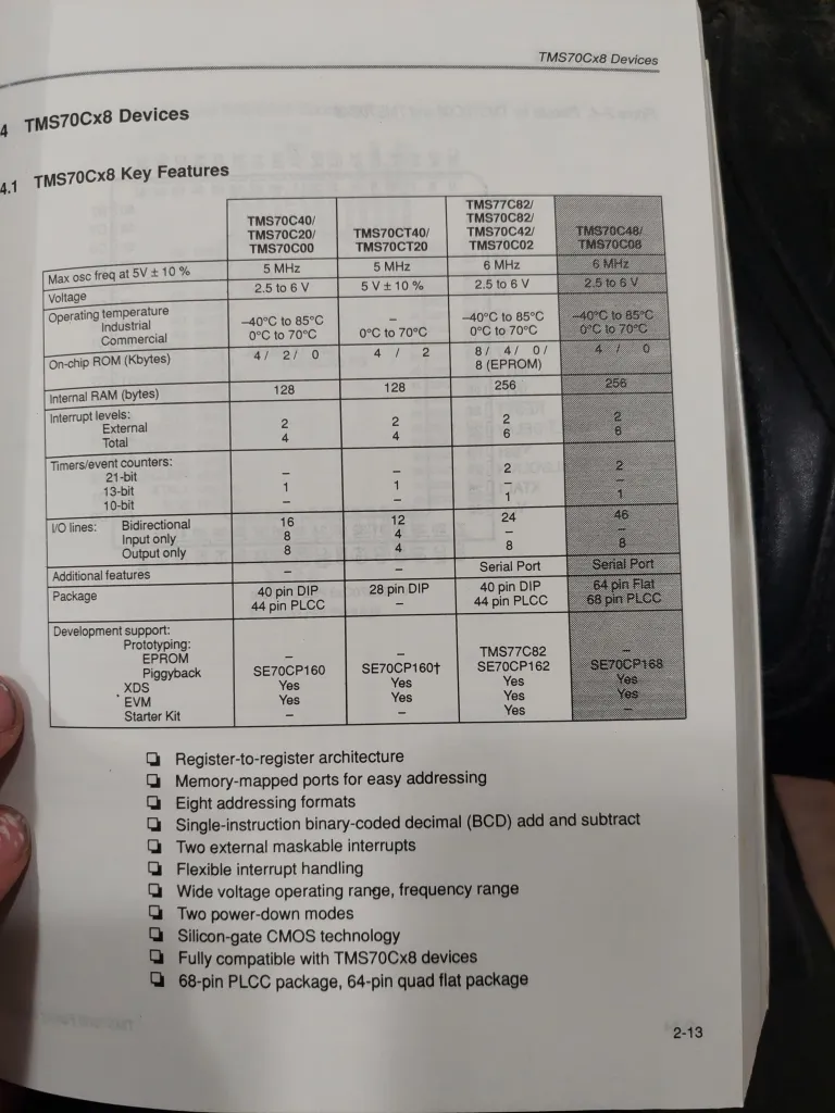
Tabellarische Übersicht der TMS70Cx8 Mikrocontroller-Merkmale
TMS70Cx8 Devices 4.1 TMS70Cx8 Key Features TMS70C40/TMS70C20/TMS70C00 Max osc freq at 5V ± 10% 5 MHz Voltage 2.5 to 6 V Operating temperature Industrial Commercial -40°C to 85°C 0°C to 70°C TMS70CT40/TMS70CT20 5 MHz 5V ± 10% 128 Internal RAM (bytes) 128 256 256 TMS70C82/TMS70C82
in „TMS70C08FNL Datenblatt“ · Mikrocontroller und Digitale Elektronik · · Fotos
-
PDF
MAX100.pdf
), 0 80 TA= T MINto MAX DIV, MOD, A=B = -0.8V,AT = MINto MAX -5 20 Digital Input High Current IH µA CLK, CLK, VIH= -0.8V (no termination), 0 80 TA= T MINto MAX LOGIC OUTPUTS (Note 9) AData, BData, TA= +25°C -1.95 -1.60 Digital
in „Oszilloskop mit AVR“ · Mikrocontroller und Digitale Elektronik ·
-
Datei
main.c
SCL_low(); SDA_write(); SDA_low(); SCL_high(); SDA_high(); } //############################### void I2C_MAX6956Init(void) { I2C_start(); // START senden I2C_init(MAX6956_BUS_ADDRESS_0, 'w'); // den sensor auslesen while (!(I2C_gotACK())); I2C_sendbyte(0x06); //Command Byte -->Clear All while (!(I2C_gotACK
in „MSP430F2013 I2C Library gesucht“ · Mikrocontroller und Digitale Elektronik ·
-
Datei
avrdude_ice_failure.txt
Using Programmer : atmelice_isp avrdude: stk500v2_jtag3_open() avrdude: usbhid_open(): Probing for max. packet size avrdude: usbhid_open(): Setting max_xfer from DAP_Info response to 512 avrdude: Found CMSIS-DAP compliant device, using EDBG protocol avrdude: jtag3_getsync() avrdude: jtag3_edbg_prepare
in „avrdude / Atmel ICE“ · Mikrocontroller und Digitale Elektronik ·
-
PDF
TMS279X_DataSheet.pdf
for side 1 II 3 L = Sector Length Flag LBS's Sector Length in ID Field 00 01 10 11 L=0 256 512 1024 128 L=1 128 256 512 1024 II 4 m = Multiple Record Flag m=0, Single record m=1, Multiple record IV 0-3 Ix = Interrupt Condition Flags 0 = 1 Not Ready to Ready Transition I = 1 Ready To Not Ready Transition
in „Floppy FDD Diskette an AVR Mikrocontroller ATmega Beispiele Assembler“ · Projekte & Code ·
-
PDF
T100_Scaler.pdf
be converted to RGB color space by using following equations, R= YCoefCSC *(Y −16)+ CrCoef_ R( Cr −128) G = YCoefCSC *(Y −16)− CrCoef_ G *(Cr− 128)−CbCoef _ G*(Cb −128) B= YCoefCSC *(Y −16)+ CbCoef _B*( Cb− 128) WhereYCoefCSC is in 1.7-bit fixed point with default 1.in 1.7-bit fixed point with default
-
Datei
io_control.c
durch __attribute__ ... ersetzen #define EEMEM __attribute__ ((section (".eeprom"))) #endif */ #define MAX 11 U8 prell = 0; U8 switch_state = 0xff; U8 schalt_merker = 0; U8 temp1; U8 temp2; U8 temp3; U8 helligkeitswert[MAX]={0,1,5,15,40,80,100,140,170,210,255}; // |- ab hier TIMER1_SCALE = CLK_8; U16 geschwindigkeitswert
in „Laufschrift auf dem HD44780“ · Mikrocontroller und Digitale Elektronik ·
-
PDF
C-Kurzfassung-V4-0-W_Apr07.pdf
bvb_s04; float zahl; // Beispielhaftes Einlesen inputse(s1,7); // Über die serielle Schnittstelle können max. // 6 Zeichen plus <RETURN> in s1 eingelesen werden *** Annahme, es werden die Zeichen <1> <8> <4> <8> und <RETURN> eingegeben *** inputse(s2,10); // Über die serielle Schnittstelle können max. // 9
in „C8051 Einführung“ · Mikrocontroller und Digitale Elektronik ·
-
PDF
C_-_Kurzfassung_-_V4-0_-_W.pdf
bvb_s04; float zahl; // Beispielhaftes Einlesen inputse(s1,7); // Über die serielle Schnittstelle können max. // 6 Zeichen plus <RETURN> in s1 eingelesen werden *** Annahme, es werden die Zeichen <1> <8> <4> <8> und <RETURN> eingegeben *** inputse(s2,10); // Über die serielle Schnittstelle können max. // 9
in „c: bit,sbit, sfr“ · Mikrocontroller und Digitale Elektronik ·
-
PDF
C-Kurzfassung-V4-0-W_Apr07.pdf
bvb_s04; float zahl; // Beispielhaftes Einlesen inputse(s1,7); // Über die serielle Schnittstelle können max. // 6 Zeichen plus <RETURN> in s1 eingelesen werden *** Annahme, es werden die Zeichen <1> <8> <4> <8> und <RETURN> eingegeben *** inputse(s2,10); // Über die serielle Schnittstelle können max. // 9
in „Einstieg in die C-Programmerung für µC“ · Mikrocontroller und Digitale Elektronik ·
-
PDF
LCD240128A.pdf
Graphic LCD Display 240*128 Model No: LCD240128A LEDSEE electronics Website: www.ledsee.com Email: info@ledsee.com June 5, 2008 Version 2.0 LEDSEE electronics Website: www.ledsee.com Email: info@ledsee.com CONTENTS 1. FEATURES
in „LCD240128A an PIC 18F4550“ · Mikrocontroller und Digitale Elektronik ·