-
 Bild
Bild
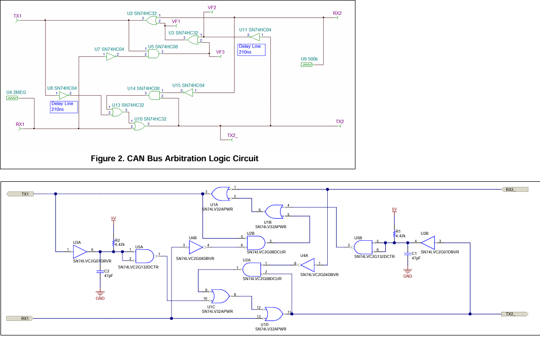
Schaltpläne einer CAN Bus Arbitrationslogik
Line 210ns U13 SN74HC32 1 3 2 U10 SN74HC32 1 2 3 TX2 U15 SN74HC04 1 2 TX2 RX1 TX1 U1A SN74LV32APWR 1 2 3 U1B SN74LV32APWR 5V R2 4.42k U5A SN74LVC2G132DCTR 1 2 C2 47pF GND U4B SN74LVC2G04DBVR 1 2 3 U2A SN74LVC2G04DBVR 3 4 U4A SN74LVC2G08DCUR 1 2 3 U3B SN74LVC2G07DBVR 3 4 R1 4.42k C1 47pF GND U1C SN74LV32APWR 8 9 10 U1D SN74LV32APWR 11 12 13 TX2 RX1
in „Funktionsweise CAN <-> LWL <-> CAN“ · Mikrocontroller und Digitale Elektronik · · Schaltpläne
-
PDF
SAM7-EX256.pdf
CRS T C 1 R 3 I _ C 4 7 D 41 TX- L COL/RMII 20 J S USB S S I C 4 U 42 TX+ K TXD3 19 COL 1 3 5 7 9 1 1 1 1 1 4 3 2 1 U U M A VDDTX P TXD2 TX3 V T 7 0 43 GND7 _ TXD1 18 TX2 . S 8n n 5 0 44 GND8 C TXD0 17 TX1 3 0 K S ) R 60 B O 6 0 z
in „SPI-Initialisierung von zwei Geräte über den gleichen Bus“ · Mikrocontroller und Digitale Elektronik ·
-
Datei
uart0.c
_TX tx_in = tx_out; #endif UCSR0B = 0 #ifdef USE_UART0_RX | (1<<RXEN0) // enable RX | (1<<RXCIE0) // enable RX interrupt #endif #ifdef USE_UART0_TX | (1<<TXEN0) // enable TX #endif ; } /* * UART0 RX */ #
in „USART-Interrupts auf Atmega lösen manchmal nicht aus“ · Mikrocontroller und Digitale Elektronik ·
-
Datei
usbdrv.h
------------------------------------------------- */ /* USB Token values */ #define USBPID_SETUP 0x2d #define USBPID_OUT 0xe1 #define USBPID_IN 0x69 #define USBPID_DATA0 0xc3 #define USBPID_DATA1 0x4b #define USBPID_ACK 0xd2 #define USBPID_NAK 0x5a #define USBPID_STALL 0x1e #ifndef USB_INITIAL_DATATOKEN
in „ATMega48 mit V-USB (AtmelStudio 6)“ · Mikrocontroller und Digitale Elektronik ·
-
PDF
HWM_MBUS-M13_v107.pdf
VDC 24V DC 5 GND Versorgung Masse nc GND GND 6 #COL Kollisions-Interrupt (siehe Kapitel 3.2) #COL #COL #COL 7 WRX do not connect nc nc nc 8 WTX do not connect nc nc nc 9 RX UART Receiver (an RX) nc RX RX 10 TX UARTTransmitter (anTX) nc TX TX Tabelle 5: Pinbelegung des Steckverbinders X1 2.4
in „M-BUS Stromauslesen“ · Mikrocontroller und Digitale Elektronik ·
-
Datei
main.c
*/ // Everflourish EWM200R { 0x15155700, 0x15155400 }, /* A1 0 */ { 0x15455700, 0x15455400 }, /* A2 1 */ { 0x15515700, 0x15515400 }, /* A3 2 */ { 0x45155700, 0x45155400 }, /* B1 3 */ { 0x45455700, 0x45455400 }, /* B2 4 */ { 0x45515700, 0x45515400 }, /* B3 5 */ { 0x51155700, 0x51155400 }, /* C1 6 */
in „Funksteckdose Elro schalten mit RFM12“ · Mikrocontroller und Digitale Elektronik ·
-
PDF
DockVision_14798V4.pdf
e 1 m CPU S m l ... K S1 S2 WIBOND TXT Einstellung Installationshinweise: 1. Das Gerät darf nur von einer Fachkraft auf- Adresse S1 (WIBOND TXT): gestellt, geöffnet und gewartet werden. 1 2 3 4 5 6 7 8 2. Es muss eine leicht zugängige
in „Ansteuerung einer Wibond-Anzeige“ · PC Hard- und Software ·
-
Datei
lpc17xx_emac.c
_t rx_buf[EMAC_NUM_RX_FRAG][EMAC_ETH_MAX_FLEN>>2]; /** Tx buffer data */ static uint32_t tx_buf[EMAC_NUM_TX_FRAG][EMAC_ETH_MAX_FLEN>>2]; /** * @} */ /* Private Functions ---------------------------------------------------------- */ static void rx_descr_init
in „LPC1768 Ethernet mit DP83848J“ · Mikrocontroller und Digitale Elektronik ·
-
Datei
msp430x20x3_ta_uart2400.c
WDTCTL = WDTPW + WDTHOLD; // Stop watchdog timer CCTL0 = OUT; // TXD Idle as Mark TACTL = TASSEL_1 + MC_2; // ACLK, continuous mode P1SEL = TXD + RXD; // P1DIR = TXD; // // Mainloop for (;;) { RX_Ready(); // UART ready to RX one Byte _BIS_SR(LPM3_bits + GIE); // Enter LPM3 w/ interr until char RXed TX_Byte
in „UART und SPI mit MSP430 (MSP430F2013), Pin-Konflikt“ · Mikrocontroller und Digitale Elektronik ·
-
Datei
msp430x20x3_ta_uart2400.c
WDTCTL = WDTPW + WDTHOLD; // Stop watchdog timer CCTL0 = OUT; // TXD Idle as Mark TACTL = TASSEL_1 + MC_2; // ACLK, continuous mode P1SEL = TXD + RXD; // P1DIR = TXD; // // Mainloop for (;;) { RX_Ready(); // UART ready to RX one Byte _BIS_SR(LPM3_bits + GIE); // Enter LPM3 w/ interr until char RXed TX_Byte
in „MSP430F20xx UART“ · Mikrocontroller und Digitale Elektronik ·
-
Datei
main.c
of SRF01 serialTX(0x5E); // Send command to get clearRXBuf(); // Clear the recieve buffer serialRX(2); // Recieve the high byte and low byte of range into rx_buf[0] and rx_buf[1] data = (rx_buf[0] <<8) + rx_buf[1]; //
in „SRF01 Ultrasonic range finder“ · Mikrocontroller und Digitale Elektronik ·
-
Datei
main.c
of SRF01 serialTX(0x5E); // Send command to get clearRXBuf(); // Clear the recieve buffer serialRX(2); // Recieve the high byte and low byte of range into rx_buf[0] and rx_buf[1] data = (rx_buf[0] <<8) + rx_buf[1]; //
in „Xmega128A1-Proximity Sensor funkt. nicht“ · Mikrocontroller und Digitale Elektronik ·
-
Datei
uart.asm
; Belegung der I/O-Ports ; ---------------------- ; ; PortB3: (MOSI) ; PortB4: (MISO) ; PortB5: (SCK) ; Testbord ; PortD0: Rx ; PortD1: Tx ; PortD2: Taster ; PortD3: Taster ; PortD4: Taster ; PortD5: LED1 ; PortD6: LED2 ; PortD7: Summer ; ; ------------------
-
Datei
nRF24L01.h
define SETUP_RETR 0x04 #define RF_CH 0x05 #define RF_SETUP 0x06 #define STATUS 0x07 #define OBSERVE_TX 0x08 #define CD 0x09 #define RX_ADDR_P0 0x0A #define RX_ADDR_P1 0x0B #define RX_ADDR_P2 0x0C #define RX_ADDR_P3 0x0D #define RX_ADDR_P4 0x0E #define RX_ADDR_P5 0x0F #define TX_ADDR 0x10 #define RX_PW_P0
in „daten vom atmega328ß zum attiny2313 mit nrf24l01 übertragen“ · Mikrocontroller und Digitale Elektronik ·
-
Datei
Untitled122.txt
i=1:length(openDAQ) , stop(openDAQ); end; %load('pn_sequenz_201.mat') %load('rxdata1.mat') %txdata=2.*x(1:44100)-1; fs = 44100; f = 441; t = 0:1/fs:1; %t_rx=0:1/fs:3.5-1/fs; % t_tx=0:1/fs:302/fs; %tx=0:1/fs:1-1/fs; s_tx = sin(2*pi*f*t); %s=[zeros(1,101) s_tx zeros(1,101)]; %d=8; %c = sin(2*pi*3*f*t)
-
Datei
Megsv.h
double *prange); int WINAPI GSVsetRanges(int no, int channel, int inx, double range); int WINAPI GSVgetTxModeConfig(int no); int WINAPI GSVsetTxModeTransmit4(int no, int t4); int WINAPI GSVgetTxModeTransmit4(int no); int WINAPI GSVsetTxModeRepeat3(int no, int r3); int WINAPI GSVgetTxModeRepeat3(int no); int WINAPI GSVsetTxModeTransmit5(int no, int t5); int WINAPI GSVgetTxModeTransmit5(int no); int WINAPI GSVsetTxModeReadOnly(int no, int ro); int WINAPI GSVgetTxModeReadOnly(int no); int WINAPI GSVsetSpecialModeSlow(int
in „Bestehende Library an C# anbinden“ · Softwareentwicklung ·
-
Datei
rfm12.inc
@ 3,3V ldi YL, 0x40 ; 1MHz: 600b / 2MHz: c06b / 2,5MHz: c08b / 5MHz: c0cb rcall rfm_com_send pop YL pop YH ret ;------------------------------------------------------------------ rfm_receive_init: push YH push YL rcall rfm_status ;
in „RFM12 Initialisierung“ · Mikrocontroller und Digitale Elektronik ·
-
Datei
UART.c
(int baur_reg) { _TRISB0=0; // TX-Pin Output _TRISB1=1; // RX-Pin Input U2MODEbits.STSEL=0; // One Stop bit U2MODEbits.PDSEL=0b00; // 8-bit data, no parity U2MODEbits.BRGH=1; // BRG generates 4 clocks per bit period (4x baud clock, High-Speed mode) U2MODEbits.RXINV=0; // UxRX Idle state is '1' U2MODEbits.ABAUD=0; // Baud rate measurement is disabled or completed U2MODEbits.UEN=0b00; // UxTX and UxRX pins are enabled and used; UxCTS and UxRTS/UxBCLK
in „Einfacher Webserver mit PIC24 + ESP8266“ · Projekte & Code ·
-
Datei
ether_top.vhd
1C", X"89", X"4D", X"00", X"01", X"02", X"03", X"04", X"05", X"06", X"07", X"08", X"09", X"0A", X"0B", X"0C", X"0D", X"0E", X"0F", X"10", X"11", X"12", X"13", X"00", X"00", others => X"00") ; signal tx_wr : std_logic := '0'; signal tx_store_CRC : std_logic := '0'; signal data_in : std_logic_vector(7
-
Datei
IICTSUS.ASM
;Temp Register einstellen - das gleiche wie für Sensor 1 jetzt für Sensor 2 durchführen call i2c_start movlw B'10010010' call i2c_tx call i2c_getack ; ACK vom LM75 empfangen movlw 0 call i2c_tx call i2c_getack ; ACK vom LM75 empfangen call i2c_stop mainloop ;### Sensor 1 ###
-
Datei
AVRootloader.asm
m8Adef.inc" ; ATmega8A ;.include "m8def.inc" ; ATmega8 ;.include "pwm216def.inc" ; AT90PWM216 ;.include "pwm2Bdef.inc" ; AT90PWM2B ;.include "pwm2def.inc" ; AT90PWM2 ;.include "pwm316def.inc" ; AT90PWM316 ;.include "pwm324def.inc" ; AT90PWM324 ;.include "pwm3Bdef.inc" ; AT90PWM3B ;.include "pwm3def.inc" ; AT90PWM3
-
PDF
SCH_ESP32-Ethernet-Kit_A_V1.2_20200528.pdf
DCDC BUCK Option MT3012NSBR RMII PHY Switch 5V-3.3V IP101GRI MAC RESET_N 5V ESP32 JTAG D+/D- Module B USB USB-UART B CNN USB-JTAG TX/RX (FT2232H) LED*2 DTR/RTS Auto EN+IO0 IO0+EN Prog Key*2 ESP32-ETHERNET-KIT_A A A Title <ESP32-Ethernet-Kit_A> SizePage Name Rev A3 <01 : DesignBlock> V1.2onfidential and
in „Arduino Library für Netzwerkchip W5500?“ · Mikrocontroller und Digitale Elektronik ·
-
Datei
mcp2515.txt
BFPCTRL */ #define B1BFS 5 #define B0BFS 4 #define B1BFE 3 #define B0BFE 2 #define B1BFM 1 #define B0BFM 0 /** \brief Bitdefinition von TXRTSCTRL */ #define B2RTS 5 #define B1RTS 4 #define B0RTS 3 #define B2RTSM 2 #define
in „MCP2515 richtig initialisiert?“ · Mikrocontroller und Digitale Elektronik ·
-
PDF
BK9520DatasheetShortEng.pdf
3 3 3 3 3 3 3 3 GPIO3/ NC 1 30 GPIO4 VDDVCO 1 24 MSSI VDDVCO 2 29 VCCIF VCCVCO 2 23 GPIO4 VCCVCO 3 28 XO2 CE 3 22 VCCIF 4 BK9521 27 SDA BK9521 CE VCCB 5 TX 26 SCK VCCB 4 TX 21 XO2 NC 6 QFN40 25 GPIO2/ NC 5 QFN32 20 SDA ADCDAT NC 7 5mmx5mm 24 GPIO1/ NC 6 4mmx4mm
in „Mehrere Stabantennen nah zusammen?“ · HF, Funk und Felder ·
-
Datei
nRF24L01.h
define SETUP_RETR 0x04 #define RF_CH 0x05 #define RF_SETUP 0x06 #define STATUS 0x07 #define OBSERVE_TX 0x08 #define CD 0x09 #define RX_ADDR_P0 0x0A #define RX_ADDR_P1 0x0B #define RX_ADDR_P2 0x0C #define RX_ADDR_P3 0x0D #define RX_ADDR_P4 0x0E #define RX_ADDR_P5 0x0F #define TX_ADDR 0x10 #define RX_PW_P0
in „NRF24L01+ mit ATMEGA328P Standalone“ · Mikrocontroller und Digitale Elektronik ·
-
Datei
nRF24L01.h
define SETUP_RETR 0x04 #define RF_CH 0x05 #define RF_SETUP 0x06 #define STATUS 0x07 #define OBSERVE_TX 0x08 #define CD 0x09 #define RX_ADDR_P0 0x0A #define RX_ADDR_P1 0x0B #define RX_ADDR_P2 0x0C #define RX_ADDR_P3 0x0D #define RX_ADDR_P4 0x0E #define RX_ADDR_P5 0x0F #define TX_ADDR 0x10 #define RX_PW_P0
in „nrf24l01 sendet nicht“ · Mikrocontroller und Digitale Elektronik ·
-
Datei
nRF24L01.h
define SETUP_RETR 0x04 #define RF_CH 0x05 #define RF_SETUP 0x06 #define STATUS 0x07 #define OBSERVE_TX 0x08 #define CD 0x09 #define RX_ADDR_P0 0x0A #define RX_ADDR_P1 0x0B #define RX_ADDR_P2 0x0C #define RX_ADDR_P3 0x0D #define RX_ADDR_P4 0x0E #define RX_ADDR_P5 0x0F #define TX_ADDR 0x10 #define RX_PW_P0
in „NRF24L01 und Atmega328P“ · Mikrocontroller und Digitale Elektronik ·
-
Datei
usart2dmactrl.c
------------------------------------------------------------------------------ */ static void usart2_rxDmaConfig(void) { // USART2_TX DMA Ch7 DMA_DeInit(DMA1_Channel7); DMA_InitStructure.DMA_PeripheralBaseAddr = (uint32_t)&(USART2->TDR); DMA_InitStructure.DMA_MemoryBaseAddr = (uint32_t)stUsart2Ctrl.txBuf
in „STM32F303 USART2 DMA1 funktioniert halblebig ?“ · Mikrocontroller und Digitale Elektronik ·
-
Datei
lpc43xx_cgu.c
2013 // 3 I E E G T X P P P x x D D D D D S U P U M S S P P A A L E S S S U U U U C x x x x A O O // 2 R R T P C T L L L I I I I I A S E S 4 P P H H P P C N D S S R R R R O P U U // C X X I K A 0 A 1 A B C D E F B R B F I RxTx1 3 D T I 0 1 0 1 2 3 L T T {0,0,0,0,0,0,0,1,1,1,0,0,1,1,1,1,1,0,0,1,1,1,1,1,1,1,1,1,1,1,1,1,1,1,1,1,1,1,0,0,0,0,1,1,1
in „Cortex M0/M4 SPI nach CMSIS ?“ · Mikrocontroller und Digitale Elektronik ·
-
PDF
um3750.pdf
. 18 V c c The positive power supply pin of the UM3750. 2 - 5 B t E z F - _ z___ _ --~ UM3750 Connection Diagram for Transmitter/Receiver Output Waveform (based on 100 KHz) Typical 2 - 6 Decoder Flowchart Stand by Mode Reset Count Yes No No + Data In? N O Count - Count +1 Reset 64m s, is 128ms, Timer 64ms Timer Overflow Yes _ ! ?: _ I - N o Activates the TX//RX Output No Yes V TX,‘RX Output Ordering Information I Part No. Package 1 2 - 7
-
Datei
IPCONFIG.txt
mode #define MY_DEFAULT_WEP_KEYS_LONG { {{0x00,0x01,0x02,0x03,0x04,0x05,0x06,0x07,0x08,0x09,0x0A,0x0B,0x0C}},\ {{0x10,0x11,0x12,0x13,0x14,0x15,0x16,0x17,0x18,0x19,0x1A,0x1B,0x1C}},\ {{0x20,0x21,0x22,0x23,0x24,0x25,0x26,0x27,0x28,0x29,0x2A,0x2B,0x2C}},\ {{0x30,0x31,0x32,0x33,0x34,0x35,0x36,0x37,0x38,0x39,0x3A
in „TCP/IP Stack Konfiguration des GenericTCPServers“ · Mikrocontroller und Digitale Elektronik ·
-
PDF
RC17xxHP-RC232_Datasheet.pdf
prompt before any further action is done to ensure correct re-configuration. TCONFIG- 1.42 ms IDLE tTX Min 12 ms tTX= # bytes to send x 1.67 ms/byte (at 4.8 kbit/s) + 2 bytes preamble, sync + 2 bytes address + 2 bytes CRC TRSSI 20 ms Time from end of S command to start of RSSI byte received on UART Application
in „[V] RADIOCRAFTS RC1701HP-RC232 169MHz Development Kit“ · Markt ·
-
Datei
CMU_BASE.INI.TXT
B-F-I // frontend ADC PMGR=-B-F-I-S // path manager RXTX1=-B-F // C331/1 RXTX2=-B-F // C331/2 331MIR_1=-B-F-I // Data Mirror for C331/1 331MIR_2=-B-F-I // Data Mirror for C331/2 StuCtrl=-B-F-I // Startup Control LH_CDMA1=-B-F-I LH_CDMA2=-B-F-I LH_CD2K1=-B-F-I LH_CD2K2=-B-F-I CTC=-B-F-I // Correction Table Check ULH1=-B-F-I ULH2=-B-F-I ABIS=-B-F-I USU1_ULH=-B-F-I USU2_ULH=-B-F-I USU1_PPC=-B-F-I USU2_PPC=-B-F-I COPRO=-B-F-I
in „Option B41 bei einer CMU200 nachrüsten.“ · HF, Funk und Felder ·
-
Datei
kueche_2.lst
----------------------------------------------------- ; initialize USART ; use r24 usart_init: 0000b2 e680 ldi r24, low(rxbuf) 0000b3 2e88 mov rxhead, r24 0000b4 2e98 mov rxtail, r24 0000b5 e08b ldi r24, low(UTimer) ;initialize baud rate timer 0000b6 b989 out UBRR, r24 .if AVR!=8515 0000b7 e080 ldi r24, high(UTimer) 0000b8 b982 out UBRRH, r24 .endif 0000b9 9892 cbi TxEnPort, TxEnBit ;RS485 transmitter initially disabled 0000ba 9a8a sbi TxEnDDR, TxEnBit .if MultiProc .else ; receiver enabled with interrupt ; transmitter
-
PDF
PIC24FJ256DA210_Development_Board_User_s_Guide__.pdf
connected to P1. To access the UART through the PICtail Plus expansion port: 1. Set jumper J16 to position 2-3 (U1TX – TX). 2. Set jumper J17 to position 2-3 (U1RX – RX). In this configuration, the U1RX and U1TX signals appear at pins 2 and 4 of the PICtail Plus connector, respectively. 2010 Microchip Technology
in „VGA Display am PIC24FJ256DA210 läuft nicht“ · Mikrocontroller und Digitale Elektronik ·
-
PDF
EMS_V2_Schaltplan.pdf
BC857ASMD GND 1 k 5 R 4 _ 5 6 0 M _ EMS_TX R 2 E M 1 1 1 1 RA5 GND E 9 9 9 9 1N4148SMD EMS_5V 0 2 2 2 2 1 7 0 R R R R 8 B 1 k 4 2 IC6 9 4 B R 5 IC1B R 330 R25 8 D 1 C14 MCLR/ R 7 EMS_TX VIN VOUT EMS_5V t4 3 2 1 EMS_232_TX 6 C12 78L05SMD C13 +
in „Buderus EMS-"Gateway" mit PIC18F / Sammelbestellung“ · Haus & Smart Home ·
-
Datei
rfm12.inc
@ 3,3V ldi YL, 0x00 ; 1MHz: 600b / 2MHz: c06b / 2,5MHz: c08b / 5MHz: c0cb rcall rfm_com_send pop YL pop YH ret ;------------------------------------------------------------------ rfm_receive_init: push YH push YL rcall rfm_status ;
in „RFM12 Statusabfrage“ · Mikrocontroller und Digitale Elektronik ·
-
PDF
EMS_V2_Plan.pdf
R 330 R19 8 D 1 8 D1 B 1 k 4 1 EMS_TX VIN VOUT EMS_5V C16 5 1N4148SMD B R 5 IC1B R C10 78L05SMD C11 2 k 7 100n R 1 D2 EMS_232_TX 6 330n GND 10n 4 1N4148SMD LM393D T1 2 3 6 7 Q2 BC847 EMS_GND BC857ASMD 5 7 EMS_GND EMS_GND 6
in „Buderus EMS-"Gateway" mit PIC18F / Sammelbestellung“ · Haus & Smart Home ·
-
Datei
bascom_dmx.txt
lösen willst denk dich mal in folgendes Konstrukt: (r16) enthält den zu sendenden Wert: $asm sbi PortB, PinNr ' Beginn Startbit rcall pause '*** cbi PortB, PinNr ' TX-Leitung auf jeden Fall löschen btsc r16, 7 ' ist Bit 7 gesetzt? ja-> im nächsten Befehl TX auf High sbi PortB, PinNr ' nein -> dieser Befehl wird geskippt, TX bleibt Low rcall Pause '*** '*** cbi PortB, PinNr ' TX-Leitung auf jeden Fall löschen btsc r16, 6 ' ist Bit 7 gesetzt? ja-> im nächsten Befehl TX auf High sbi PortB, PinNr ' nein -> dieser Befehl wird
in „DMX senden & Bascom“ · Mikrocontroller und Digitale Elektronik ·
-
Datei
main.c
Tranceive Modus wechseln TxModus(); } else{ //In den Receive Modus wechseln RxModus(); //delay(); } SPI_Send_2Byte(SNOP, 0x00); while(1) { if(sender==1){ //TX SPI_Send_Strobe(SIDLE); PowerDown(); SPI_Send_2Byte(0x3F, 0xB6); //
in „CC2500 Programm Ablauf (Tx/Rx Modus)“ · HF, Funk und Felder ·
-
Datei
rfm12.cpp
#include "rfm12.h" #include "rfm12_cmds.h" #include "spi.h" #define STATE_RX_IDLE 1 #define STATE_TX_ACTIVE 2 #define STATE_TX_FINISHED 3 //default synchronization pattern #define SYNC_MSB 0x2D #define SYNC_LSB 0xD4 #define PREAMBLE 0xAA #define PWRMGMT_LOW_BATT 0 #define PWRMGMT_WKUP 0 #define RFM12
in „RFM12BSP - Kein nIRQ beim Empfang“ · Mikrocontroller und Digitale Elektronik ·
-
Datei
main.c
; /* ʹÓñê׌id */ TxMessage.DLC = 8; /* ÊýŸÝ³€¶È, can±šÎĹ涚×îŽóµÄÊýŸÝ³€¶ÈΪ8×ÖœÚ */ TxMessage.Data[0] = CAN_DATA0; TxMessage.Data[1] = CAN_DATA1; TxMessage.Data[2] = CAN_DATA2; TxMessage.Data[3] = CAN_DATA3; TxMessage.Data[4] = CAN_DATA4; TxMessage.Data[5] = CAN_DATA5; TxMessage.Data[6] = CAN_DATA6; TxMessage.Data[7] = CAN_DATA7; CAN_Transmit(CAN1,&TxMessage); /* ·µ»ØÕâžöÐÅÏ¢ÇëÇó·¢Ë͵ÄÓÊÏäºÅ0,1,2»òûÓÐÓÊÏäÉêÇë·¢ËÍno_box */ } /***********
in „STM32 can Message“ · Mikrocontroller und Digitale Elektronik ·
-
Datei
rfm70.h
command #define RFM70_READ_RX_PAYLOAD 0x61 // Define RX payload register address #define RFM70_WRITE_TX_PAYLOAD 0xA0 // Define TX payload register address #define RFM70_FLUSH_TX 0xE1 // Define flush TX register command #define RFM70_FLUSH_RX 0xE2 // Define flush RX register command #define RFM70_WRITE_TX_PAYLOAD_NOACK
in „RFM70 und ATMega16 benötige Hilfe!!“ · Mikrocontroller und Digitale Elektronik ·
-
Datei
ism.asm
macro ldw ldi R24,LOW(@0) ldi R25,HIGH(@0) .endm ldi R16,stack rjmp start correct_hamming_table: .db 2,$80,$20,0,8,0,0,0 .org 6 rjmp timer rjmp recv_int rjmp trans_int hamming_table: .db $15,$02,$49,$5E,$64,$73,$38,$2F,$D0,$C7,$8C,$9B,$A1,$B6,$FD,$EA bitrate_table: .db 129,64,32,21,15,10 data_rate_table
in „Beispielprogramm für RFM12 433MHz Funk-Module“ · Projekte & Code ·
-
PDF
HausAutoTest1808.pdf
11 LED 1 18 10 2 1 14 SER QA 15 1B M 1C R 1 2 2B C 2C 17 9 D6 R21 QB 3 3B 3C 16 8 1 LED 1 N 11 SRCLK QC 2 4 15 7 X 2 1 2 G 5V 10 SRCLR QD 3 4B 4C 1 5 4 5 5B 5C 14 6 _ D3 J 3 Ub+ QE 6 13 5 N R 4 12 RCLK QF 5 6B 6C O LED
in „Layout prüfen“ · Platinen ·
-
Datei
uart0.c
= bauddivider; // set baud rate UCSR0A = 0; // no U2X, MPCM UCSR0C = 1<<UCSZ01^1<<UCSZ00 // 8 Bit #ifdef URSEL0 ^1<<URSEL0 // if UCSR0C shared with UBRR0H #endif ; UCSR0B = 1<<RXEN0^1<<TXEN0^ // enable RX, TX 1<<RXCIE0; // enable RX interrupt rx_in = rx_out
in „Hilfe, komme nicht weiter. Temperatur von 0 bis -1 Grad kein negatives Vorzeichen.“ · Mikrocontroller und Digitale Elektronik ·
-
PDF
BERECHNUNG_SEARCH.pdf
Master sendet F0h undRE Suchalgorithmus empfängt 2 Bits (A) und complement (B), 1. Suchlauf 2. Suchlauf 3. Suchlauf 4. Suchlauf 0 1 2 3 0 1 2 3 0 1 2 3 0 1 2 3 Diskrepanzen I TITIT I I TIT I I I TITIT I I TIT I I zwischen B B B B B B B B B B B B B B
in „DS1820 DS18S20 1-wire Suchalgorithmus Suchalgorithmen“ · Mikrocontroller und Digitale Elektronik ·
-
Datei
enc28j60.c
/** MAC address. Should be set using a function.*/ const uint8_t bytMacAddress[6] = {0x10,0x12,0xE2,0x10,0x10,0xD0}; TXSTATUS TxStatus; // define private functions static uint8_t ReadETHReg(uint8_t); // read a ETX reg static uint8_t ReadMacReg(uint8_t); // read a MAC reg static uint16_t ReadPhyReg(
in „Problem mit ENC28J60“ · Mikrocontroller und Digitale Elektronik ·
-
Datei
p16f15214.inc
EQU H'00119' TX1REG EQU H'0011A' SP1BRG EQU H'0011B' SP1BRGL EQU H'0011B' SP1BRGH EQU H'0011C' RC1STA EQU H'0011D' TX1STA EQU H'0011E' BAUD1CON EQU H'0011F' SSP1BUF EQU H'0018C' SSP1ADD EQU H'0018D' SSP1MSK EQU H'0018E
in „PIC MPMASMX PIC-AS“ · Mikrocontroller und Digitale Elektronik ·
-
PDF
AVR-DD-Product-Brief-DS40002215A-1.pdf
0,TxD MOSI (3) SDA(M) (3) WO0 LUT0,IN0 EXTCLK (7) XTAL32K2 (3) (3) 31 23 18 5 5 PA1 0,RxD MISO SCL(M) WO1 LUT0,IN1 XTALHF2 TWI 0,XCK 32 24 19 6 PA2 AIN22 SDA(M) WO2 0,WO EVOUTA LUT0,IN2 Fm+ 0,TxD(3) TWI 0
in „AVR-DD im Anrollen“ · Mikrocontroller und Digitale Elektronik ·