-
PDF
2sk3115.pdf
±30 V, VDS = 0 V ±100 nA Gate Cut-off Voltage V GS(off) VDS = 10 V, I = 1 mA 2.5 3.5 V Forward Transfer Admittance | y | VDS = 10 V, I = 3.0 A 2.0 S Drain to Source On-state Resistance R DS(on) VGS = 10 V, I = 3.0 A 0.9 1.2 Input Capacitance C iss VDS = 10 V 1100 pF Output Capacitance C oss VGS = 0 V 200 pF Reverse Transfer Capacitance C rss f = 1 MHz 20 pF Turn-on Delay Time td(on) VDD = 150 V, I = 3.0 A 18 ns Rise Time t VGS(on= 10 V 12 ns Turn-off Delay Time td(off) R = 10 , R = 50 50 ns Fall Time t 15 ns Total Gate
in „Reparatur Schaltnetzteil“ · Analoge Elektronik und Schaltungstechnik ·
-
PDF
70070938397.pdf
particular thermal interface material and “Heat Flow Calculation for 3M Thermally Conductive Adhesive Transfer Tapes.” Thermal Interface Thermal interface materials are those which are useful for establishing an effective Materials thermal path between a heat-generating component (e.g., a transistor) and a
in „Frage zu Parametern von Wärmeleitpaste“ · Analoge Elektronik und Schaltungstechnik ·
-
PDF
Cascaded_PP_Buck.pdf
the current- thecircuitmidpoint(V PP,andDisthebuck-switch fed push-pull topology. duty cycle. The transfer function for the push-pull Avionicsandmilitarypowerconvertershaveused stage is V ⫽V /N, where N is the transformer OUT PP the current-fed topology for a couple of decades. turns ratio. The composite transfer function of the Current-fed push-pull is a “cascaded” topology, of two cascaded stages is thenV OUT⫽V *INN. whichmanyvarietiesexist.Thisarticleexaminessev- Anexamplewithidealswitches,a2.5Voutputand
in „Cascaded Buck - Push Pull Wandler“ · Mikrocontroller und Digitale Elektronik ·
-
PDF
Datasheet__ICM-20948_.pdf
(03h) Type: USR3 Bank: 3 Serial IF: R/W Reset Value: 0x00 BIT NAME FUNCTION 7 I2C_SLV0_RNW 1 – Transfer is a read. 0 – Transfer is a write. 6:0 I2C_ID_0[6:0] Physical address of I C slave 0. 11.5 I2C_SLV0_REG Name: I2C_SLV0_REG Address: 4 (04h) Type: USR3 Bank: 3 Serial IF: R/W Reset Value: 0x00 BIT
in „20948 I2C <-> SPI?“ · Mikrocontroller und Digitale Elektronik ·
-
PDF
SMB380_Preliminary_Datasheet_Rev13_20070918.pdf
Data Sheet SMB380 Bosch Sensortec Triaxial acceleration sensor Start and stop conditions: Data transfer begins by a falling edge on SDA when SCK is high (start condition (S) indicated by I²C bus master). Stop condition (P) is a rising edge on SDA when SCK is high (see figure 12). Bit transfer: One data
in „Problem SMB380“ · Mikrocontroller und Digitale Elektronik ·
-
Datei
STMPE811QTR.c
IOE_I2C,ENABLE); /* Enable DMA TX Channel */ DMA_Cmd(IOE_DMA_TX_STREAM, ENABLE); /* Wait until DMA Transfer Complete */ IOE_TimeOut = TIMEOUT_MAX; while (!DMA_GetFlagStatus(IOE_DMA_TX_STREAM,IOE_DMA_TX_TCFLAG)) { if (IOE_TimeOut-- == 0) { return(IOE_TimeoutUserCallback()); } } /* Wait until BTF Flag is
in „STM32F4 Touch Display Interrupt“ · Mikrocontroller und Digitale Elektronik ·
-
PDF
LIDAR_Lite_v3.pdf
automatic incrementing of the register address with successive reads or writes within an I2C block transfer. This is commonly used to read the two bytes of a Technology 16-bit value within one transfer and is used in the following example. This device measures distance by calculating the time delay between
in „BeagleboneBlack: Sensor über I2C“ · Mikrocontroller und Digitale Elektronik ·
-
PDF
LIDAR_Lite_v3.pdf
automatic incrementing of the register address with successive reads or writes within an I2C block transfer. This is commonly used to read the two bytes of a Technology 16-bit value within one transfer and is used in the following example. This device measures distance by calculating the time delay between
in „BeagleboneBlack: Sensor über I2C“ · Mikrocontroller und Digitale Elektronik ·
-
PDF
lidar_lite_v3_operation_manual_and_technical_specifications.pdf
automatic incrementing of the register address with successive reads or writes within an I2C block transfer. This is commonly used to read the two bytes of a Technology 16-bit value within one transfer and is used in the following example. This device measures distance by calculating the time delay between
in „Belegung Lidat V1 (2)“ · Mikrocontroller und Digitale Elektronik ·
-
PDF
AD7302.pdf
nV-s and measured with a full-scale code change on line passing through the endpoints of the DAC transfer function. the data bus, i.e., from all 0s to all 1s and vice versa. A graphical representation of the transfer curve is shown in Figure 14. DIGITAL CROSSTALK Digital Crosstalk is the glitch impulse
in „(S) AD7302BNZ DAC DIP20“ · Markt ·
-
PDF
8051_Befehlssatz.pdf
Wert) E:\PersDat\StarOffice\Mc-51\Mikrocontroller-2.sxi © 05.09.05, J. Rathlev, IEAP-Kiel, Seite 3 Transfer-Befehle (Daten kopieren): Kopieren eines Datenbytes aus dem und in den internen Speicher / SFR: MOV A,Rn 1 B 1 Z dadr,A 2 B 1 Z A,dadr 2 B 1 Z dadr,Rn 2 B 2 Z A,@Ri 1 B 1 Z dadr,dadr 3 B 2 Z A,#konst8
in „Assembler Tabellen ( 8051)“ · Mikrocontroller und Digitale Elektronik ·
-
Datei
spi_mem_drv.h
DATA 0x4 //! The SPI interface is ready to send #define READY_TO_SEND 0x0 //Access Status #define TRANSFER_STARTED 0x0 //!< The write access is started whithout error #define TRANSFER_COMPLETED 0x1 //!< The read access is completed whithout error #define OUT_OF_RANGE 0xFD //!< The address is out of range
in „Grafikfähiger LCD Controller für 320x240 LCD mit 4 Graustufen“ · Projekte & Code ·
-
Datei
0001-Fix-data-loss-in-cdc-acm.patch
size; + if (!urb->actual_length) - return; + return 0; - tty_insert_flip_string(&acm->port, urb->transfer_buffer, + size = tty_insert_flip_string(&acm->port, urb->transfer_buffer, urb->actual_length); tty_flip_buffer_push(&acm->port); + if ( size < urb->actual_length ) { + printk(KERN_WARNING "cdc_acm
in „Virtuelle serielle Schnittstelle verliert Daten“ · Softwareentwicklung ·
-
Datei
epd.c
0x00, 0x00, 0x00, 0x00, 0x13, 0x14, 0x44, 0x12, 0x00, 0x00, 0x00, 0x00, 0x00, 0x00 }; void SPI_Transfer(uint8_t dat) { EPD_CS_LAT = 0; SPI_Exchange8bit(dat); EPD_CS_LAT = 1; } void EpdSendCommand(uint8_t cmd) { EPD_DC_LAT = 0; SPI_Transfer(cmd); } void EpdSendData(uint8_t dat) { EPD_DC_LAT = 1; SPI_Transfer
in „Fragen zu Waveshare e-paper 1.54"“ · Mikrocontroller und Digitale Elektronik ·
-
Datei
I2CPort.cpp
GPIO_PUPDR_PUPDR7; } void I2CPort::initI2C() { // In Master mode, the I2C interface initiates a data transfer and generates the clock signal. // A serial data transfer always begins with a Start condition and ends with a Stop condition. // Master mode is selected as soon as the Start condition is generated
in „I2C auf dem STM32 F411RE“ · Mikrocontroller und Digitale Elektronik ·
-
Datei
mitsumi.txt
Descriptor) bEndpointAddress : 0x01 (Direction=OUT EndpointID=1) bmAttributes : 0x02 (TransferType=Bulk) wMaxPacketSize : 0x0040 (64 bytes) (64 bytes) bInterval : 0x00 (ignored) ----------------- Endpoint Descriptor ----------------- bLength : 0x07 (7 bytes) bDescriptorType : 0x05 (Endpoint Descriptor) bEndpointAddress : 0x83 (Direction=IN EndpointID=3) bmAttributes : 0x03 (TransferType=Interrupt) wMaxPacketSize : 0x0002 (2 bytes) (2 bytes) bInterval : 0x7F (127 ms)
in „Erfahrungen mit alten Disketten gesucht“ · PC Hard- und Software ·
-
Datei
triple_interleaved.c
ADC_RegularChannelConfig(ADC3, ADC_CHANNEL, 1, ADC_SampleTime_3Cycles); ADC_DMARequestAfterLastTransferCmd(ADC1, ENABLE); /* Enable DMA request after last transfer (multi-ADC mode) ******************/ // ADC_MultiModeDMARequestAfterLastTransferCmd(ENABLE); /* Enable ADC1 ****************************
in „STM32, triple mode Interleaved mode, periodisch falsch“ · Mikrocontroller und Digitale Elektronik ·
-
PDF
bourns_bd241-1159109.pdf
= 5 V I = 0 1 mA EBO current EB C h Forward current VCE = 4 V IC= 1 A (see Notes 5 and 6) 25 FE transfer ratio V = 4 V I = 3 A 10 CE C Collector-emitter VCE(sat) saturation voltage B = 0.6 A IC= 3 A (see Notes 5 and 6) 1.2 V Base-emitter VBE voltage VCE = 4 V IC= 3 A (see Notes 5 and 6) 1.8 V Small signal forward hfe VCE = 10 V IC= 0.5 A f = 1 kHz 20 current transfer ratio Small signal forward |fe VCE = 10 V IC= 0.5 A f = 1 MHz 3 current transfer ratio NOTES: 5. These parameters must be measured using pulse techniqups, t = 300 µs, duty cycle ≤ 2%. 6. These parameters
in „[V] Komplementäre 27St. BD241A und 10St BD242A und Reste geschenkt“ · Markt ·
-
PDF
bourns_bd242-1159279.pdf
V I = 0 -1 mA EBO current EB C h Forward current VCE = -4 V C = -1 A (see Notes 5 and 6) 25 FE transfer ratio V = -4 V I = -3 A 10 CE C Collector-emitter VCE(sat) saturation voltage B = -0.6 A C = -3 A (see Notes 5 and 6) -1.2 V Base-emitter VBE voltage VCE = -4 V C = -3 A (see Notes 5 and 6) -1.8 V Small signal forward hfe VCE = -10 V C = -0.5 A f = 1 kHz 20 current transfer ratio Small signal forward |fe| VCE = -10 V C = -0.5 A f = 1 MHz 3 current transfer ratio NOTES: 5. These parameters must be measured using pulse techniquesp t = 300 µs, duty cycle ≤ 2%. 6. These
in „[V] Komplementäre 27St. BD241A und 10St BD242A und Reste geschenkt“ · Markt ·
-
PDF
ft232r08.pdf
FT8U232AM U-UART - USB UltraBaud Data Transfer IC with RS232 / RS422 and CPU I/F Options FEATURES • Single Chip Multi-Function Data Transfer Virtual COM Port Drivers for – Solution Windows 98 and Windows 98 SE • RS232 link from 300 baud to 920K
in „AVR - USB - Interface“ · Mikrocontroller und Digitale Elektronik ·
-
PDF
4A-AT-Espressif_AT_Instruction_Set_020.pdf
is connected to the server, it will take up one connection,be gave an id. 6.2.8AT+ CIPMODE – Set transfer mode AT+ CIPMODE – Set transfer mode 20/ 23 Espressif Systems June 16, 2014 ESP8266EX AT Instruction Set Type :Query Response: Function: + CIPMODE:<mode> Query transfer mode. Instruction: OK Param description: AT+ CIPMODE? The same as below. Type :Set Response: Function: Set transfer mode. OK Instruction: If already connected, returns Link is builded AT+CIPMODE=<mode> Param description: <mode>0 normal mode 1 unvarnished transmission mode 6.2.9AT+ CIPSTO – Set server timeout AT
in „Wlan2Serial Modul für 5 euro“ · Mikrocontroller und Digitale Elektronik ·
-
PDF
ADE7758.pdf
output should be tied to a negative-edge- The CS input should be driven low for the entire data transfer triggered external interrupt on the MCU. On detection of the operation. Bringing CS high during a data transfer operation negative edge, the MCU should be configured to start executing aborts the
in „Energy Meter mit ADE7769 - AVR“ · Mikrocontroller und Digitale Elektronik ·
-
Datei
CH552.H
USB suspend or resume event interrupt flag, direct bit address clear or write 1 to clear sbit UIF_TRANSFER = USB_INT_FG^1; // USB transfer completion interrupt flag, direct bit address clear or write 1 to clear sbit UIF_BUS_RST = USB_INT_FG^0; // bus reset event interrupt flag, direct bit address clear
in „uC für 0,20€ CH552 / CH554 von WCH Billig Micro mit USB Funktion, Chip vorstellung“ · Mikrocontroller und Digitale Elektronik ·
-
PDF
ADC0804_NSC.pdf
only will center-value www.national.com 16 A D Functional Description (Continued) Next to each transfer function is shown the corresponding C error plot. Many people may be more familiar with error plots 8 Figure 2 shows a worst case error plot for the ADC0801. All than transfer functions. The analog
in „Probleme Verständnis ADC 0804-1“ · Mikrocontroller und Digitale Elektronik ·
-
PDF
DVD_Service_Manual.pdf
/ Vertical MTBF : 125,000 POH <DVD-ROM> 1) Single layered disc : 6.7 to 16X max. Full CAV, data transfer : 22.1 Mbytes/s max. Dual layered disc : 5 to 12X max. Full CAV, data transfer : 16.6 Mbytes/s max. Video disc (w/CSS) : 3.3 to 8X max. Full CAV, data transfer : 11.1 Mbytes/s max. 2) High speed access
in „DVD-Laufwerk DVS-7150V reparieren“ · PC Hard- und Software ·
-
PDF
ADC0801_05.pdf
only will center-value www.national.com 16 A D Functional Description (Continued) Next to each transfer function is shown the corresponding C error plot. Many people may be more familiar with error plots 8 Figure 2 shows a worst case error plot for the ADC0801. All than transfer functions. The analog
in „Verständnisfrage zum ADC080x (VIN-MIN/DC-Offset)“ · Analoge Elektronik und Schaltungstechnik ·
-
PDF
doc4688.pdf
SCL is used to clock the data in and out of the device. SDA is a bi-directional line and used to transfer data into and out of the device. The following protocol is used for the data transfers. 4.4.1 Serial Protocol Data states on the SDA line change only when SCL is low. Changes in the SDA line while
in „Die I2C Schnittstelle eines PIC16F876A initialisieren“ · Mikrocontroller und Digitale Elektronik ·
-
PDF
GD32F3x0_RM_v1.0.pdf
9-1. DMA transfer operation Transfer size Transfer operations Source Destination Source Destination 1: Read B3B2B1B0[31:0] @0x0 1: Write B3B2B1B0[31:0] @0x0 2: Read B7B6B5B4[31:0] @0x4 2: Write B7B6B5B4[31:0] @0x4
in „"NUCLEO"-Borads von GigaDevice“ · Mikrocontroller und Digitale Elektronik ·
-
PDF
GD32F3x0_RM_v1.0.pdf
9-1. DMA transfer operation Transfer size Transfer operations Source Destination Source Destination 1: Read B3B2B1B0[31:0] @0x0 1: Write B3B2B1B0[31:0] @0x0 2: Read B7B6B5B4[31:0] @0x4 2: Write B7B6B5B4[31:0] @0x4
in „"NUCLEO"-Borads von GigaDevice“ · Mikrocontroller und Digitale Elektronik ·
-
PDF
doc6462.pdf
the PDC by a bidirectional channel. This channel has two 32-bit memory pointers, one for current transfer and the other for next transfer. These pointers point to transmit or receive data depending on the operating mode of the peripheral. Depending on the type of transfer (byte, half-word or word), the
in „Externes SRAM + Atmel AT91SAM7SE“ · Mikrocontroller und Digitale Elektronik ·
-
PDF
Ezurio-Datenblatt.pdf
(SPP), Dial Up Networking Profile (DUN), Headset Profile (HSP), Hands Free Profile (HFP), File Transfer Profile (FTP) and Audio Gateway. A virtual processor is used within the BC04 to implement an AT command processor. This interfaces to the host system over a straight forward serial port using an extensive
in „Ezurio Bluetooth-Modul => PC erkennt es nicht“ · Mikrocontroller und Digitale Elektronik ·
-
 Bild
Bild
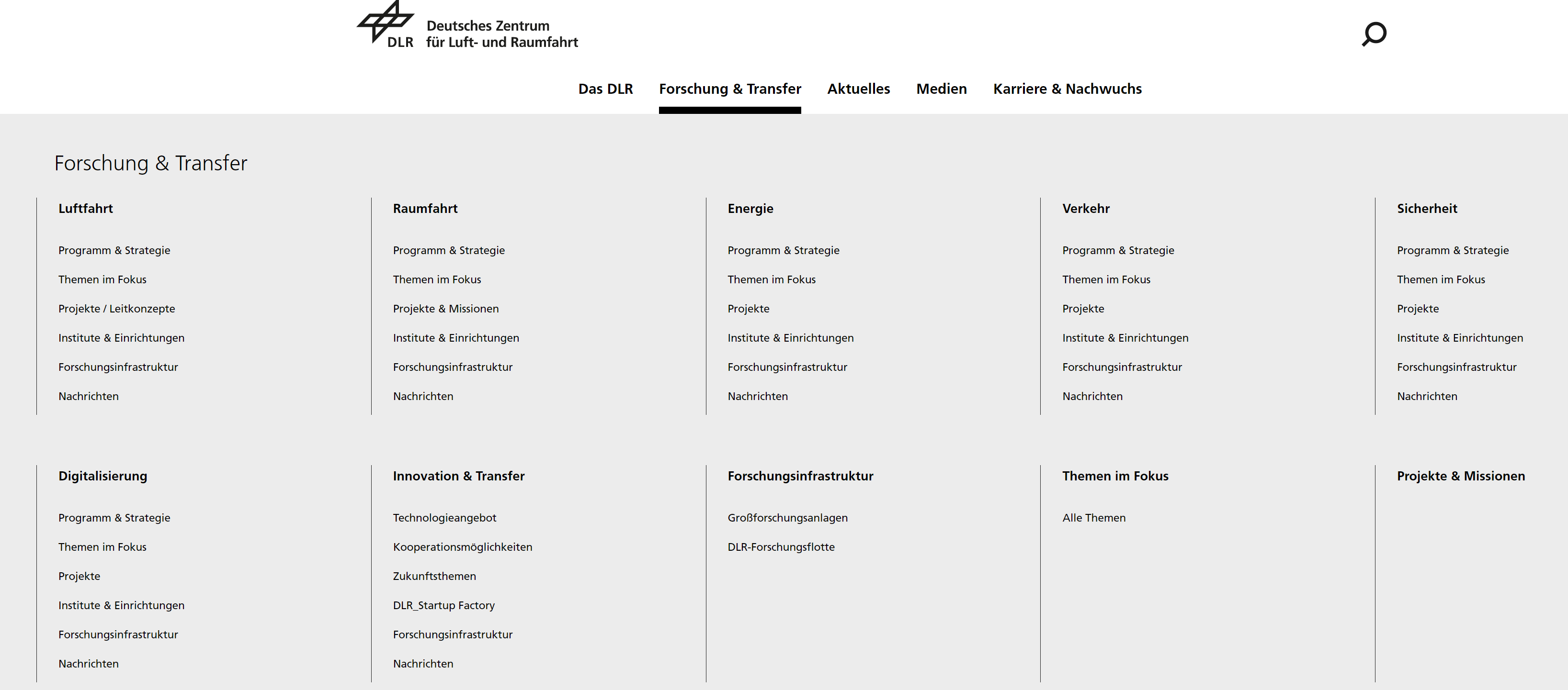
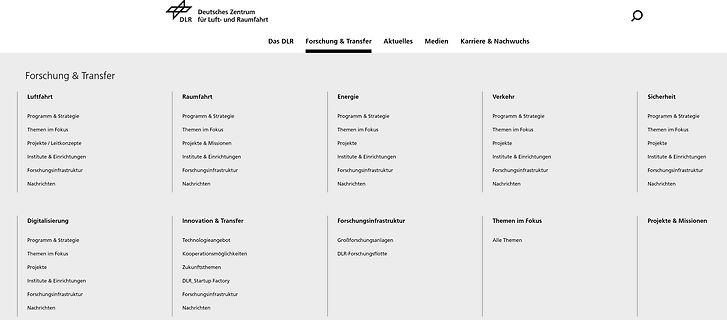
Screenshot der DLR Webseite Forschungs- und Transferbereiche
Deutsches Zentrum für Luft- und Raumfahrt DLR Das DLR Forschung & Transfer Aktuelles Medien Karriere & Nachwuchs Luftfahrt Raumfahrt Energie Verkehr Sicherheit Digitalisierung Innovation & Transfer Forschungsinfrastruktur Themen im Fokus Projekte / Leitkonzepte Institute
in „Abschlussarbeit am DLR ratsam?“ · Ausbildung, Studium & Beruf · · Screenshots
-
PDF
TCRT1000_datasheet.pdf
outputs D Low temperature coefficient D Detector provided with optical filter A C E C D Current Transfer Ratio (CTR) of typical 2.5% Top view Order Instruction Ordering Code Sensing Distance Remarks TCRT1000 A) 1 mm B) TCRT1010 1 mm Document Number 83752 www.vishay.com Rev. A3, 27–May–99 1 (7) TCRT1000
in „Bauteilidentifikation - Infrarotempfaenger?“ · Mikrocontroller und Digitale Elektronik ·
-
PDF
SPCA533A_ist_in_einer_Polaroid.pdf
of image parts, image rotation, … etc. DMA Controller: The DMA controller allows high-speed data transfer between SPCA533A internal modules. Storage Media Interface Controller: The storage interface controller is a high efficiency bridge between different storage media protocol and the internal bus. Both DMA data transfer and PIO data transfer are supported. Audio Controller: The SPCA533A’s audio controller has built-in standard IMA-ADPCM audio compression. It also integrates the AC-link interface. USB1.1 Controller
in „SmartMedia auf xD-Picture Card“ · Mikrocontroller und Digitale Elektronik ·
-
Datei
ADC_DMA.c
USART_DATA_LEN], sendingUSART[USART_DATA_LEN]; // sending is only for debugging! volatile uint8_t DMA_transfer_complete = 1; uint8_t Rx = 0, tmp, test_send; void delay(void) { volatile float temp = 9999999; uint32_t i; for (i=0; i<25000; i++) { temp /= 99999999; temp *= 999999999; temp /= 99999999; temp *=
in „STM32L1: USART Tx (und Rx) mit DMA funktioniert nur sporadisch“ · Mikrocontroller und Digitale Elektronik ·
-
PDF
XMEGA-1.pdf
AVR • load, store; in, out; push and pop only instructions using databus • Allows high-speed data transfer • Memory <-> Peripheral • Memory -> Memory • Peripheral -> Peripheral www.atmel.com CONFIDENTIAL 4 Event System • Highlights • 8 Event Routing Channels • CPU and DMA independent operation • Quadrature
in „Einladung: XMEGA AVR - Vortrag der Firma Atmel“ · Mikrocontroller und Digitale Elektronik ·
-
Datei
main_XMC4500.c
Prescaler Input Clock is the Module Clock; * Suspend requests are ignored; Multi Channel shadow transfer only by software; * Only the shadow transfer for period and compare values is requested */ CCU40->GCTRL = 0x00000000; } void CCUInit_channel(void) { CCU40_CC40->TC = 0x00000002; // Inhalt des Registers
in „XMC4500 vs stm32f429.warum gibt es Unterschiede in der Berechnungsdauer?“ · Mikrocontroller und Digitale Elektronik ·
-
PDF
D130858D.PDF
BR)EBO E C breakdownvoltage Collector cutoff current ICES — — 500 A VCE 1500V, R =BE DC current transfer ratio h 10 — 30 V = 5 V, I = 1A FE1 CE C DC current transfer ratio h 3.5 — 6.5 V = 5 V, I = 7A FE2 CE C Collector to emitter V — — 5 V I = 7A, I = 1.8A CE(sat) C B saturationvoltage Base to emitter
in „Transistor am Arduino“ · Mikrocontroller und Digitale Elektronik ·
-
PDF
311RevD_Manual.PDF
work with 32-bit, 33 MHz, 5 V PC/104+ bus. An important system requirement is fast PCI-to-DRAM transfer. Some PC/104+ CPU designs may not provide bandwidth sufficient for image transfer, which may result in image corruption. 5 Specifications Video sources NTSC, PAL, SECAM, RS-170, CCIR Video inputs
-
Datei
assembler_O2.txt
4924 ldr r1, [pc, #144] @ (80004e4 <InitEndpoints+0x98>) { 8000452: b4f0 push {r4, r5, r6, r7} CMD.TransferLen = 0; // nothing to transfer 8000454: 2400 movs r4, #0 8000456: 2500 movs r5, #0 8000458: e9c0 4502 strd r4, r5, [r0, #8] suspended = false; 800045c: 4f22 ldr r7, [pc, #136] @ (80004e8 <InitEndpoints
in „STM32G484 USB CDC Code läuft nur wenn mit <= -O1 kompiliert“ · Mikrocontroller und Digitale Elektronik ·
-
Datei
assembler_O3.txt
4924 ldr r1, [pc, #144] @ (80004e4 <InitEndpoints+0x98>) { 8000452: b4f0 push {r4, r5, r6, r7} CMD.TransferLen = 0; // nothing to transfer 8000454: 2400 movs r4, #0 8000456: 2500 movs r5, #0 8000458: e9c0 4502 strd r4, r5, [r0, #8] suspended = false; 800045c: 4f22 ldr r7, [pc, #136] @ (80004e8 <InitEndpoints
in „STM32G484 USB CDC Code läuft nur wenn mit <= -O1 kompiliert“ · Mikrocontroller und Digitale Elektronik ·
-
PDF
lm25117.pdf
Feedback Compensation Open loop response of the regulator is defined as the product of modulator transfer function and feedback transfer function. When plotted on a dB scale, the open loop gain is shown as the sum of modulator gain and feedback gain. The modulator transfer function includes a power stage
in „DC-DC Wandler mit MCP42010“ · Mikrocontroller und Digitale Elektronik ·
-
PDF
bma150.pdf
sheet BMA150 Bosch Sensortec Triaxial, digital acceleration sensor Start and stop conditions: Data transfer begins by a falling edge on SDA when SCK is high (start condition (S) indicated by I²C bus master). Stop condition (P) is a rising edge on SDA when SCK is high (see figure 12). Bit transfer: One data
in „ARDUINO: Neigungsmesser bauen (Steigung/Gefälle)“ · Mikrocontroller und Digitale Elektronik ·
-
PDF
Components_alphabetic_order.pdf
zero-bias value of internal B-E aje 2.5 capacitance vdedc 0.9 B-E charge built-in voltage for DC transfer current zedc 0.5 charge B-E exponent factor for DC transfer current B-E capacitance ratio, maximum to zero-bias value for DC ajedc 2.5 transfer current t0 0 Low current forward transit time at VBC
-
 Bild
Bild
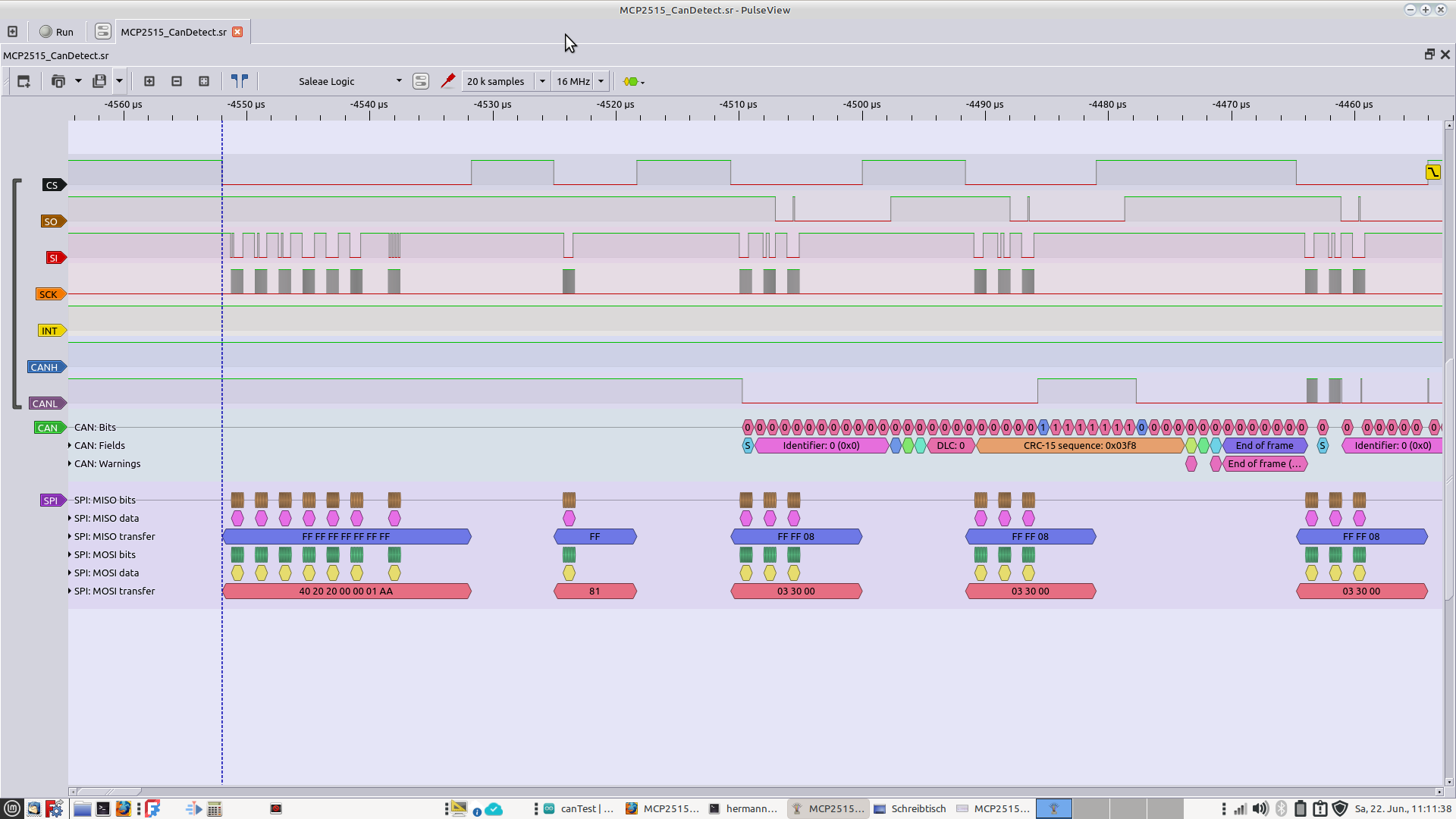
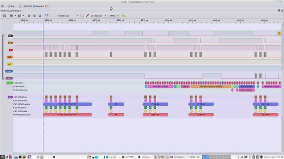
Logikanalysator-Screenshot von SPI- und CAN-Bus-Signalen
INT, CANH, CANL, CAN: Bits, CAN: Fields, CAN: Warnings, SPI: MISO bits, SPI: MISO data, SPI: MISO transfer, SPI: MOSI data, SPI: MOSI transfer, Identifier: 0 (0x0), DLC: 0, CRC-15 sequence: 0x03FB, End of frame, FF, 81, 03 30 00
in „CAN und MCP2515 - Kein Senden möglich“ · Mikrocontroller und Digitale Elektronik · · Oszi-Bilder
-
Datei
main.c
SPI_TypeDef*); unsigned char SPI_send(SPI_TypeDef*, u8); void MmcChipSelect(unsigned char Select); u8 MmcTransferByte (SPI_TypeDef* , u8 ch); /* Private functions ---------------------------------------------------------*/ /******************************************************************************* * Function
in „STM32 103RB und Probleme mit SPI1“ · Mikrocontroller und Digitale Elektronik ·
-
PDF
x24c00p.pdf
Inherent data re- • 2 Wire Serial Interface tention is greater than 100 years. —Bidirectional Data Transfer Protocol • Byte Mode Write TheX24C00isfabricatedwithXicor’sAdvancedCMOS • Self Timed Write Cycle —Typical Write Cycle Time of 5ms Floating Gate technology. • Push/Pull Output • High Reliability —Endurance
in „x24c00p Namen der Speicherzellen“ · Mikrocontroller und Digitale Elektronik ·
-
PDF
oledm128-6e.pdf
bit of the 9 bit data transfer. A busy check is not necessary at all. Clock rate may be up to 10 MHz. Data transmission is based on SPI mode 3, MSB first (9 bit). For more details please refer to the controllers data sheet SSD1306. DATA TRANSFER I²C The I²C mode provides a bi-directional data transmission: That means that data can be written and read. With the pin SA0 the I²C address can be changed, so up to 2 displays may be driven on 1
in „OLED zeigt nur wirre Pixel am I2C“ · Mikrocontroller und Digitale Elektronik ·
-
PDF
ne25139.pdf
4V, G2S = 0 µA 10 IG2SS Gate 2 Reverse Current at DS = 0, G2S = -4V, G1S = 0 µA 10 |YFS| Forward Transfer Admittance at DS = 5 V, G2S = 1 V, ID= 10 mA, f = 1.0 kHz mS 18 25 35 C ISS f = 1 MHzacitance at DS = 5 V, G2S = 1 V,DI= 10 mA, pF 0.5 1.0 1.5 CRSS D Reverse Transfer Capacitance at DS = 5 V, VG2S
in „GaAs NE25139 ersetzen“ · Analoge Elektronik und Schaltungstechnik ·
-
 Bild
Bild
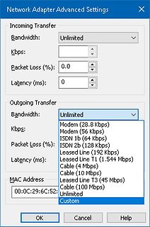
Einstellungen des Netzwerkadapters
Network Adapter Advanced Settings Incoming Transfer Bandwidth: Unlimited Kbps: Packet Loss (%): Latency (ms): Outgoing Transfer Bandwidth: Unlimited Modem (28.8 Kbps) Modem (56 Kbps) ISDN 1b (64 Kbps) ISDN 2b (128 Kbps) Leased Line (192 Kbps) Leased
in „LAN für Testzwecke definiert drosseln?“ · Offtopic · · Screenshots