-
Datei
MS-SLR.asm
;port A setup out DDRA,r16 ldi r16,0 out PORTA,r16 ldi r16,0b11111111 ;port B setup out DDRB,r16 ldi r16,0 out PORTB,r16 ldi r16,0b11111111 ;port C setup out DDRC,r16 ldi r16,0 out PORTC,r16 ldi r16,0b11111100 ;port D setup out DDRD,r16 ldi r16,0 out PORTD,r16 ldi r16,0 ;USART setup out UBRRH,r16 ldi r16,5 ;115k with 11.0592 MHz out UBRRL,r16 ldi r16,(1<<URSEL)|(3<<UCSZ0) out UCSRC,r16 ldi r16,0b10011000 ;enable USART and RXCIE/UDRIE
in „UART verursacht Reset(?)“ · Mikrocontroller und Digitale Elektronik ·
-
PDF
TWI_USI_master_slave_120303.pdf
twi_buffer, 2); In twi_buffer[1] steht dann der Status der PortPins des PCF8574. Ein anderes Beispiel: Um 16 Byte ab der 16-BitAdresse "eeprom_adr" aus einem Eeprom mit der TWI-Adresse 162 auslesen: twi_buffer[0] = 162; twi_buffer[1] = (uint8_t) (eeprom_adr >> 8); twi_buffer[2] = (uint8_t) (eeprom_adr); TWI_MA_Write
in „TWI-Master für ATMEGA in C (ohne TWI-Start/Stop, ACK/NACK)“ · Projekte & Code ·
-
Datei
ZX81_debug_drv.h
data bus to OUTPUT PORTL = d; } static inline uint8_t Z80_readDataBus() { return PINL; // read the Atmega Port Pin register } static inline void Z80_writeAddrBus(uint16_t addr) { uint8_t addrh; uint8_t addrl; addrl = addr & 0xFF; addrh = (addr >> 8) ; PORTA = addrl; PORTC = addrh; } static inline uint8_t Z80_setAddress(uint16_t adr) { setAddressbusActive(); Z80_writeAddrBus(adr); setAddressbusInactive(); } static inline void set_nWAIT(boolean bitValue) { if(bitValue) { pinMode(nWAIT,INPUT); digitalWrite(nWAIT, HIGH); }else
-
Datei
PWM.c
stdlib.h> #include <string.h> #include <stdio.h> #include <inttypes.h> //globale Variable für die PWM uint16_t pwmTable_8[] = {0, 4, 8, 16, 32, 64, 128, 255}; #define ARRAY_SIZE(x) (sizeof(x)/sizeof(*x)) //----------------- long delays void my_delay(uint16_t milliseconds) { for(; milliseconds > 0; milliseconds
in „Probleme mit der Verbindung PWM + ADC“ · Mikrocontroller und Digitale Elektronik ·
-
Datei
HSV_RGB_10bitPWM.asm
; Div(H) ;.def accu2 = r17 ; result HSV_Div256: lsl accu3 ; accu3(H):accu2(L) /2 = /2 rol accu2 ; =16Bit rechts-schieben lsl accu3 ; accu3(H):accu2(L) /2 = /4 rol accu2 ; =16Bit rechts-schieben lsl accu3 ; accu3(H):accu2(L) /2 = /8 rol accu2 ; =16Bit rechts-schieben lsl accu3 ; accu3(H):accu2(L) /2 = /16 rol accu2 ; =16Bit rechts-schieben lsl accu3 ; accu3(H):accu2(L) /2 = /32 rol accu2 ; =16Bit rechts-schieben lsl accu3 ; accu3(H):accu2(L) /2 = /64 rol accu2 ; =16Bit rechts-schieben lsl accu3 ; accu3
in „DMX - PWM generieren“ · Mikrocontroller und Digitale Elektronik ·
-
Datei
diff.txt
40c44 < #define LCD_COLS 5 // 10col display (2*5) - only required for wrap --- > #define LCD_COLS 16 // 10col display (2*5) - only required for wrap 123a128 > #if defined (__AVR_ATtiny2313__) || defined (__AVR_ATtiny2313A__) 125a131,134 > #else // atMega > TCCR0 ^= 0x06 << CS00; // T0 falling edge >
in „Reziproker Frequenzzähler+ Optimierte 64bit uint Routinen“ · Projekte & Code ·
-
Datei
rc5.c
Funktion gibt das zu sendende Telegramm an PortB.1 aus * * * *ACHTUNG!!!! FUNKTIONIERT NUR MIT DEM ATMEGA8!!! * *Da alle Zeiten in der Senderoutine auf des Taktfrequenz des ATmega8 ba- * *sieren und keine fertigen Wartezeiten verwendet werden, sind Trägerfre- * *quenz und Periodendauer auch nur mit dem ATmega8 (evtl. anderer Prozessor* *mit gleicher Taktzeit) entsprechend dem RC5-Protokoll. * * * *Für die Verwendung dieser Funktion im Hauptprogramm wird * *die Verwendung folgender Syntax empfohlen: * *
in „Verwendung einer .h und .c; AVR“ · Mikrocontroller und Digitale Elektronik ·
-
Datei
t6963c.h
#define DDR(x) (*(&x - 1)) /* address of data direction register of port x */ #if defined(__AVR_ATmega64__) || defined(__AVR_ATmega128__) /* on ATmega64/128 PINF is on port 0x00 and not 0x60 */ #define PIN(x) ( &PORTF==&(x) ? _SFR_IO8(0x00) : (*(&x - 2)) ) #else #define PIN(x) (*(&x - 2)) /* address
-
 Bild
Bild
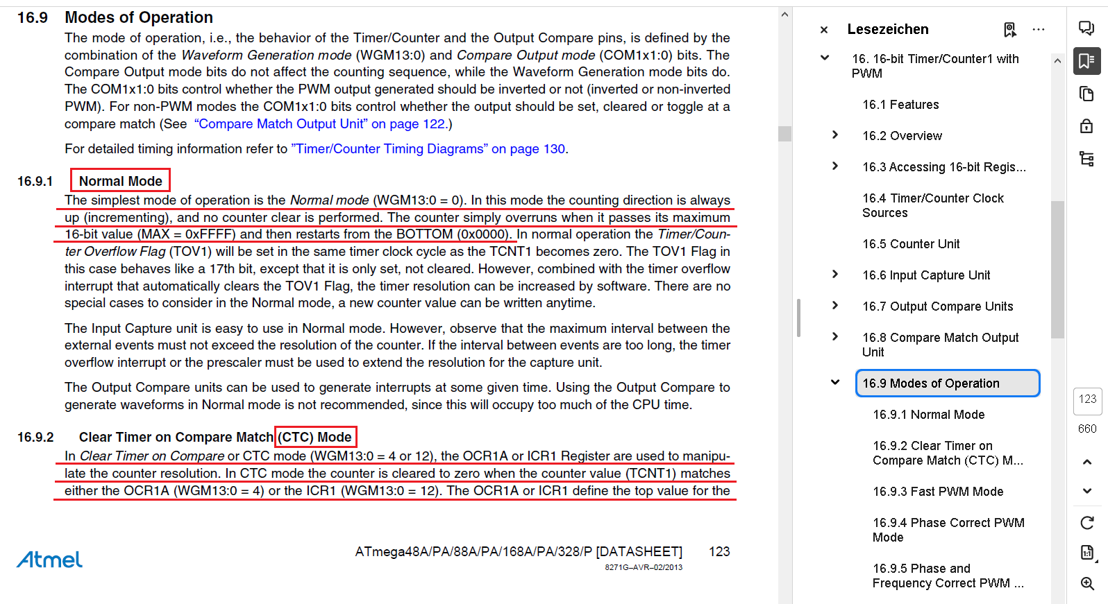
Ausschnitt aus einem Atmel Datenblatt zu Timer-Modi
16.9 Modes of Operation 16.9.1 Normal Mode 16.9.2 Clear Timer on Compare Match (CTC) Mode Atmel ATmega48A/PA/88A/PA/168A/PA/328/P [DATASHEET] Lesezeichen 16.9 Modes of Operation
in „Atmega - Multiplex-Display-Ansteuerung fehlerhaft“ · Mikrocontroller und Digitale Elektronik · · Screenshots
-
Datei
sender.c
uint8_t m=0; uint8_t n1=0; int8_t n2=0; uint16_t AVGHelligkeit=0; uint16_t Helligkeit=0; uint16_t genautemp=2512; uint32_t Temp1=0; uint32_t Temp2=0; uint32_t AVGTemp1[2]; uint32_t AVGTemp2[2]; uint16_t T1=0; uint16_t T2=0; int8_t zusatz=0; uint16_t phwert=65; uint16_t leitwert=35; uint16_t AVGphwert; uint16_t AVGleitwert; int16_t leit; uint16_t ph; int16_t zwleit; volatile uint8_t Register; volatile uint16_t min=650; volatile uint16_t tag=310; volatile uint8_t x1
in „16bit Zeichen über SPI übertragen“ · Mikrocontroller und Digitale Elektronik ·
-
PDF
Using_the_Siemens_S65_Display.pdf
01 November 2005 ) About the Display: Siemens used for the mobile phones S65, M65, CX65 and SK65 a 16-bit color TFT display with 132x176 pixel. This display has integrated white backlight LED's and an attractive screen size. The display is available for less than 20 EUR in phone part shops and ebay.
in „The Siemens S65 132x176, 65536 color display with AVR“ · Projekte & Code ·
-
PDF
Using_the_Siemens_S65_Display.pdf
April 18 , 2006 ) About the Display: Siemens used for the mobile phones S65, M65, CX65 and SK65 a 16-bit color TFT display with 132x176 pixel. This display has integrated white backlight LED's and an attractive screen size. The display is available for less than 20 EUR in phone part shops and ebay.
in „The Siemens S65 132x176, 65536 color display with AVR“ · Projekte & Code ·
-
PDF
Using_the_Siemens_S65_Display.pdf
April 18 , 2006 ) About the Display: Siemens used for the mobile phones S65, M65, CX65 and SK65 a 16-bit color TFT display with 132x176 pixel. This display has integrated white backlight LED's and an attractive screen size. The display is available for less than 20 EUR in phone part shops and ebay.
in „Reengineering: Siemens S65 Display“ · Mikrocontroller und Digitale Elektronik ·
-
Datei
aufgabe4.asm
.nolist ; include-file nicht in Listing .include "m128def.inc" ; Definitionen für ATmega 128 einbinden .list ; Listing erstellen .def akku = r16 ; r16 als Rechenregister "akku" definieren .def msTimer = r23 ; r23 als Zeit-Einstellungsregister ; r24 als Zählregister .def templ = r17 ; Zwischenspeicher
in „16Bit Timer Problem (läuft nicht) | ATmega128“ · Mikrocontroller und Digitale Elektronik ·
-
Datei
Main_Test_3.asm
Headerdatei ;HHHHHHHHHHHHHHHHHHHHHHHHHHHHHHHHHHHHHHHHHHHHHHHHHHHHHHHHHHHHHHHHHHHHHHHHHHHHHHH ;Der ATmega8 laeuft mit 1,8418432 MHz und wird an 5V betrieben. ; ;Es soll der Fehler gefunden werden, warum nicht in die TWI-Interrupt-Service- ;Routine gesprungen wird bzw. warum im ATMEL-Studio7 nicht das TWINT-Bit
in „AVR8ASM TWI Interrupt“ · Mikrocontroller und Digitale Elektronik ·
-
Datei
debug_error.asm
level changes uint16_t last_time = 0; // time of previous signal edge (in microseconds) uint16_t current_time = 0; // time of current signal edge (in microseconds) uint16_t duration = 0; // time between the last two signal
in „Fehler bei einfacher Integer-Division?“ · Mikrocontroller und Digitale Elektronik ·
-
Datei
lcd.h
display */ #define LCD_LINES 2 /**< number of visible lines of the display */ #define LCD_DISP_LENGTH 16 /**< visibles characters per line of the display */ #define LCD_LINE_LENGTH 0x40 /**< internal line length of the display */ #define LCD_START_LINE1 0x00 /**< DDRAM address of first char of line 1 */
in „LCD von Peter Fleury“ · Mikrocontroller und Digitale Elektronik ·
-
Datei
lcd.h
display */ #define LCD_LINES 1 /**< number of visible lines of the display */ #define LCD_DISP_LENGTH 16 /**< visibles characters per line of the display */ #define LCD_LINE_LENGTH 0x40 /**< internal line length of the display */ #define LCD_START_LINE1 0x00 /**< DDRAM address of first char of line 1 */
in „1*16 LCD _mit Peter Fleury's LCD library“ · Mikrocontroller und Digitale Elektronik ·
-
Datei
LCD.h
display */ #define LCD_LINES 2 /**< number of visible lines of the display */ #define LCD_DISP_LENGTH 16 /**< visibles characters per line of the display */ #define LCD_LINE_LENGTH 0x40 /**< internal line length of the display */ #define LCD_START_LINE1 0x00 /**< DDRAM address of first char of line 1 */
in „WinAVR Studio gibt Fehlermeldung aus beim "Build Projekt"“ · Mikrocontroller und Digitale Elektronik ·
-
Datei
lcd.h
display */ #define LCD_LINES 2 /**< number of visible lines of the display */ #define LCD_DISP_LENGTH 16 /**< visibles characters per line of the display */ #define LCD_LINE_LENGTH 0x40 /**< internal line length of the display */ #define LCD_START_LINE1 0x00 /**< DDRAM address of first char of line 1 */
in „Grafikfähiger LCD Controller für 320x240 LCD mit 4 Graustufen“ · Projekte & Code ·
-
Datei
lcd.h
display */ #define LCD_LINES 2 /**< number of visible lines of the display */ #define LCD_DISP_LENGTH 16 /**< visibles characters per line of the display */ #define LCD_LINE_LENGTH 0x40 /**< internal line length of the display */ #define LCD_START_LINE1 0x00 /**< DDRAM address of first char of line 1 */
in „Kompilieren von C Dateien in Kubuntu“ · Mikrocontroller und Digitale Elektronik ·
-
Datei
lcd.h
display */ #define LCD_LINES 2 /**< number of visible lines of the display */ #define LCD_DISP_LENGTH 16 /**< visibles characters per line of the display */ #define LCD_LINE_LENGTH 0x40 /**< internal line length of the display */ #define LCD_START_LINE1 0x00 /**< DDRAM address of first char of line 1 */
in „Kompilieren von C Dateien in Kubuntu“ · Mikrocontroller und Digitale Elektronik ·
-
Datei
lcd.h
display */ #define LCD_LINES 4 /**< number of visible lines of the display */ #define LCD_DISP_LENGTH 16 /**< visibles characters per line of the display */ #define LCD_LINE_LENGTH 0x40 /**< internal line length of the display */ #define LCD_START_LINE1 0x00 /**< DDRAM address of first char of line 1 */
in „LCD Displaytech 164a“ · Mikrocontroller und Digitale Elektronik ·
-
Datei
lcd.h
display */ #define LCD_LINES 2 /**< number of visible lines of the display */ #define LCD_DISP_LENGTH 16 /**< visibles characters per line of the display */ #define LCD_LINE_LENGTH 0x40 /**< internal line length of the display */ #define LCD_START_LINE1 0x00 /**< DDRAM address of first char of line 1 */
in „Atmega32 PortB freigeben, freischalten“ · Mikrocontroller und Digitale Elektronik ·
-
Datei
lcd.h
display */ #define LCD_LINES 4 /**< number of visible lines of the display */ #define LCD_DISP_LENGTH 16 /**< visibles characters per line of the display */ #define LCD_LINE_LENGTH 0x40 /**< internal line length of the display */ #define LCD_START_LINE1 0x80 /**< DDRAM address of first char of line 1 */
in „LCD Initialisierung mit Fleury“ · Mikrocontroller und Digitale Elektronik ·
-
Datei
lcd.h
display */ #define LCD_LINES 2 /**< number of visible lines of the display */ #define LCD_DISP_LENGTH 16 /**< visibles characters per line of the display */ #define LCD_LINE_LENGTH 0x40 /**< internal line length of the display */ #define LCD_START_LINE1 0x00 /**< DDRAM address of first char of line 1 */
in „Programmoptimierung“ · Mikrocontroller und Digitale Elektronik ·
-
Datei
lcd.h
display */ #define LCD_LINES 2 /**< number of visible lines of the display */ #define LCD_DISP_LENGTH 16 /**< visibles characters per line of the display */ #define LCD_LINE_LENGTH 0x40 /**< internal line length of the display */ #define LCD_START_LINE1 0x00 /**< DDRAM address of first char of line 1 */
in „LCD Controller KS0073 Support im 4-Bit Mode“ · Projekte & Code ·
-
Datei
lcd.h
display */ #define LCD_LINES 2 /**< number of visible lines of the display */ #define LCD_DISP_LENGTH 16 /**< visibles characters per line of the display */ #define LCD_LINE_LENGTH 0x40 /**< internal line length of the display */ #define LCD_START_LINE1 0x00 /**< DDRAM address of first char of line 1 */
in „LCD mit ATMEGA128 und Peter Fleury“ · Mikrocontroller und Digitale Elektronik ·
-
Datei
lcd.h
display */ #define LCD_LINES 2 /**< number of visible lines of the display */ #define LCD_DISP_LENGTH 16 /**< visibles characters per line of the display */ #define LCD_LINE_LENGTH 0x40 /**< internal line length of the display */ #define LCD_START_LINE1 0x00 /**< DDRAM address of first char of line 1 */
in „Hilfe zu fleurys Lcd Lib“ · Mikrocontroller und Digitale Elektronik ·
-
Datei
lcd.h
display */ #define LCD_LINES 2 /**< number of visible lines of the display */ #define LCD_DISP_LENGTH 16 /**< visibles characters per line of the display */ #define LCD_LINE_LENGTH 0x40 /**< internal line length of the display */ #define LCD_START_LINE1 0x00 /**< DDRAM address of first char of line 1 */
in „Probleme mit Wintek 2704 am STK500“ · Mikrocontroller und Digitale Elektronik ·
-
Datei
lcd.h
display */ #define LCD_LINES 2 /**< number of visible lines of the display */ #define LCD_DISP_LENGTH 16 /**< visibles characters per line of the display */ #define LCD_LINE_LENGTH 0x40 /**< internal line length of the display */ #define LCD_START_LINE1 0x00 /**< DDRAM address of first char of line 1 */
in „LCD Routine Peter Fleury“ · Mikrocontroller und Digitale Elektronik ·
-
Datei
lcd.h
display */ #define LCD_LINES 4 /**< number of visible lines of the display */ #define LCD_DISP_LENGTH 16 /**< visibles characters per line of the display */ #define LCD_LINE_LENGTH 0x40 /**< internal line length of the display */ #define LCD_START_LINE1 0x00 /**< DDRAM address of first char of line 1 */
in „Attiny2313 mit HD44780 LCD“ · Mikrocontroller und Digitale Elektronik ·
-
Datei
lcd.h
display */ #define LCD_LINES 4 /**< number of visible lines of the display */ #define LCD_DISP_LENGTH 16 /**< visibles characters per line of the display */ #define LCD_LINE_LENGTH 0x40 /**< internal line length of the display */ #define LCD_START_LINE1 0x00 /**< DDRAM address of first char of line 1 */
in „Attiny2313 mit HD44780 LCD“ · Mikrocontroller und Digitale Elektronik ·
-
Datei
lcd.h
display */ #define LCD_LINES 2 /**< number of visible lines of the display */ #define LCD_DISP_LENGTH 16 /**< visibles characters per line of the display */ #define LCD_LINE_LENGTH 0x40 /**< internal line length of the display */ #define LCD_START_LINE1 0x00 /**< DDRAM address of first char of line 1 */
in „HMC-16223 (HDD44780 kompatibel) zeigt kein ASCII nur "?", "_" usw“ · Mikrocontroller und Digitale Elektronik ·
-
Datei
lcd.h
display */ #define LCD_LINES 2 /**< number of visible lines of the display */ #define LCD_DISP_LENGTH 16 /**< visibles characters per line of the display */ #define LCD_LINE_LENGTH 0x40 /**< internal line length of the display */ #define LCD_START_LINE1 0x00 /**< DDRAM address of first char of line 1 */
in „HIlfe - AVR an LCD - Fleury lib“ · Mikrocontroller und Digitale Elektronik ·
-
Datei
lcd.h
display */ #define LCD_LINES 2 /**< number of visible lines of the display */ #define LCD_DISP_LENGTH 16 /**< visibles characters per line of the display */ #define LCD_LINE_LENGTH 0x40 /**< internal line length of the display */ #define LCD_START_LINE1 0x00 /**< DDRAM address of first char of line 1 */
in „LCD funktioniert nicht“ · Mikrocontroller und Digitale Elektronik ·
-
Datei
lcd.h
display */ #define LCD_LINES 4 /**< number of visible lines of the display */ #define LCD_DISP_LENGTH 16 /**< visibles characters per line of the display */ #define LCD_LINE_LENGTH 0x40 /**< internal line length of the display */ #define LCD_START_LINE1 0x00 /**< DDRAM address of first char of line 1 */
in „LCD tc1604a mit ATMEGA16“ · Mikrocontroller und Digitale Elektronik ·
-
Datei
lcd.h
display */ #define LCD_LINES 2 /**< number of visible lines of the display */ #define LCD_DISP_LENGTH 16 /**< visibles characters per line of the display */ #define LCD_LINE_LENGTH 0x40 /**< internal line length of the display */ #define LCD_START_LINE1 0x00 /**< DDRAM address of first char of line 1 */
in „avr dude Programm zu groß? Eclipse GCC“ · Mikrocontroller und Digitale Elektronik ·
-
Datei
Mega8.h
Compiler // (C) 1998-2004 Pavel Haiduc, HP InfoTech S.R.L. // I/O registers definitions for the ATmega8 #ifndef _MEGA8_INCLUDED_ #define _MEGA8_INCLUDED_ #pragma used+ sfrb TWBR=0; sfrb TWSR=1; sfrb TWAR=2; sfrb TWDR=3; sfrb ADCL=4; sfrb ADCH=5; sfrw ADCW=4; // 16 bit access sfrb ADCSRA=6; sfrb ADMUX
in „<<Problem mit DS1820>>“ · Mikrocontroller und Digitale Elektronik ·
-
 Bild
Bild
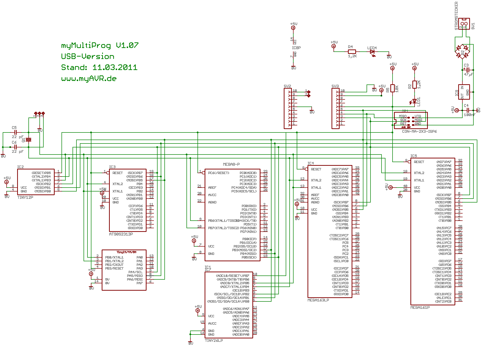
Schaltplan eines AVR-Mikrocontroller-Programmierers
myMultiProg U1.07 USB-Version Stand: 11.03.2011 www.myAVR.de IC2 TINY16 IC3 ATmega8 IC4 MEGA8 16P IC5 MEGA16 16P IC1 TINY26P SV1 SV2 LED4 R4 C1 C2 C3 C4
in „Schaltung Quarz fragen“ · Mikrocontroller und Digitale Elektronik · · Schaltpläne
-
PDF
TechnicalReference_IspV2.pdf
.. 14 2.5 Programmieren von Mikrocontrollern...................................................... 16 2.6 Betriebsmodi........................................................................................... 19 2.6.1 Bootloader Modus..................................................................
in „unbekanntes Board / Programmer ib-markl“ · Mikrocontroller und Digitale Elektronik ·
-
PDF
Arduino_Mega_schematics.pdf
14 H C e r i a s 37 PC0 18 17 PC1 36 PL4 pwm 39 PL4(OC5B) (T1)PD6 49 RXD3 7 15 T R h r e a C 35 PC2 16 15 PC3 34 PL3 pwm 38 48 TXD2 6 16 M . d l m C 33 PC4 14 13 PC5 32 PL2 37 PL3(OC5A) (XCK1)PD5 47 RXD2 5 17 L F i e e n d 31 PC6 12 11 PC7 30 PL1 36 PL2(T5) (ICP1)PD4 46 TXD1 4 18 o f i t r 29 PA7 10 9
in „Arduino Mega 2560, schaltschranktauglich“ · Projekte & Code ·
-
Datei
StateMachine.asm
O G R A M M I N I T ; ============================================ ; Main: ; Initiire Stapel ldi r16, HIGH(RAMEND) ; Initiiere MSB Stapel out SPH,r16 ldi r16, LOW(RAMEND) ; Initiiere LSB Stapel out SPL,r16 ldi State, 0x00 ldi r24, 0 ldi r16, 0 out DDRB, r16 ldi r16, 0xFF out DDRC, r16 out DDRD, r16
in „Registerinhalt ändert sich“ · Mikrocontroller und Digitale Elektronik ·
-
Datei
mmb.vhd
downto 0); AVR_AH: in std_logic_vector(7 downto 0); AVR_ALE,AVR_RD,AVR_WR: in std_logic; -- A0-A7, A15,A16,A17,A18, CS~ AL: out std_logic_vector(7 downto 0); AH: out std_logic_vector(3 downto 0); CS: out std_logic_vector(2 downto 0) ); end MMB; -- 512Kb SRAM pinning -- CS~ -> CPLD.CS(2) -- WR\ -> AVR.WR\
in „128kByte Ram an AVR“ · Mikrocontroller und Digitale Elektronik ·
-
Datei
dehgeber.c
Zoltan http://ngrad.bei.t-online.de/ Date: 25.07.03 Purpose: Software: AVR-GCC to compile Hardware: ATMEGA8 (8Mhz) Note: */ #include <avr/io.h> #include <avr/interrupt.h> #include <avr/signal.h> #include <inttypes.h> // um Register auch bitweise in Binärformat ansprechen zu können #define BIN8(b7,b6,b5,
in „Drehimpulsgeber“ · Mikrocontroller und Digitale Elektronik ·
-
Datei
leds1.asm
*********************** ;Beschreibung: ;Dieses Programm lässt eine LED am Pin0 des Ports B eines ATmega8 ;mit 2Hz blinken (Bei 4MHz Oszillator-Frequenz). ;Ein Timer (TC0) zählt nach oben bis zum Überlauf, woraufhin ;ein TC0-Überlauf-Interrupt erzeugt wird und zur "TIM0_OVF"-ISR verzweigt wird, ;die dann
in „ATmega8 Timer Problem“ · Mikrocontroller und Digitale Elektronik ·
-
Datei
leds1.asm
*********************** ;Beschreibung: ;Dieses Programm lässt eine LED am Pin0 des Ports B eines ATmega8 ;mit 2Hz blinken (Bei 4MHz Oszillator-Frequenz). ;Ein Timer (TC0) zählt nach oben bis zum Überlauf, woraufhin ;ein TC0-Überlauf-Interrupt erzeugt wird und zur "TIM0_OVF"-ISR verzweigt wird, ;die dann
in „ATmega8 Timer Problem“ · Mikrocontroller und Digitale Elektronik ·
-
Datei
auschaltverz_gerung.c
12.02.2012 */ /* Purpose: Toggeln aller 8 LEDs */ /* Software: AVR-GCC / AVR Studio 4.12 */ /* Hardware: ATmega16/Megacard */ /* Note: fclk=12MHz Description: Diese Firmware ist für einen ATMEGA16 mit 12MHz Quarz geschrieben, es soll dabei am Ausgang PB3 (OCR0, PWM) eine PWM ausgegeben werden, die es ermöglicht
in „ATMEGA16 Timer“ · Mikrocontroller und Digitale Elektronik ·
-
Datei
Drehgeber_per_interrupt.ino
Drehgeberauswertung per Interrupt auf einem AVR. Das gezeigte C-Beispielprogramm läuft auf einem ATmega328. Hier wurde testweise ein Arduino UNO R3 verwendet, da ohne große Löterei Stromversorgung und Datenausgabe über den USB-Anschluß erledigt werden. Zum Test wurde ein mechanischer Drehgeber verwendet
in „Drehgeber per Interrupt auswerten, AVR“ · Projekte & Code ·
-
Datei
main.c
TCCR1 = (1 << CTC1) | (1 << CS11) | (1 << CS10); // switch CTC Mode on, set prescaler to 4 #else // ATmegaXX: OCR1A = (F_CPU / F_INTERRUPTS) - 1; // compare value: 1/15000 of CPU frequency TCCR1A = (1 << WGM12) | (1 << CS10); // switch CTC Mode on, set prescaler to 1 #endif #ifdef TIMSK1 TIMSK1 |= 1 <<
in „Konzeption einer IR Fernbedienung“ · Mikrocontroller und Digitale Elektronik ·