-
PDF
cd4017b-mil.pdf
, protrusions, or gate burrs. Mold flash, protrusions, or gate burrs shall not exceed 0.15 mm per side. 4. This dimension does not include interlead flash. Interlead flash shall not exceed 0.25 mm per side. 5. Reference JEDEC registration MO-153. www.ti.com EXAMPLE BOARD LAYOUT PW0016A TSSOP - 1.2 mm
in „SPS erweitern für 32 Temperatureingänge“ · Analoge Elektronik und Schaltungstechnik ·
-
PDF
TBD62783AFG_datasheet_en_20160511.pdf
do the derating with 7.7 mW/°C. Note3: On PCB (Size: 50 mm × 50 mm × 1.6 mm, Cu area: 40%, single-side glass epoxy). When Ta exceeds 25°C, it is necessary to do the derating with 7.7 mW/°C. Note4: On PCB (Size: 75 mm × 114 mm × 1.6 mm, Cu area: 20%, single-side glass epoxy). When Ta exceeds 25°C, it
in „Treiber Pendant zu ULN2803“ · Mikrocontroller und Digitale Elektronik ·
-
PDF
MC14584B.pdf
MOLD FLASH, PROTRUSIONS OR GATE BURRS. MOLD FLASH OR GATE BURRS SHALL NOT N EXCEED 0.15 (0.006) PER SIDE. 0.25 (0.010) 2XL/2 14 8 4. DIMENSION B DOES NOT INCLUDE INTERLEAD FLASH OR PROTRUSION. M INTERLEAD FLASH OR PROTRUSION SHALL NOT EXCEED 0.25 (0.010) PER SIDE. L B 5. DIMENSION K DOES NOT INCLUDE −U
in „[VS] CMOS Inverter mit Schmitttriggereingang 4584“ · Markt ·
-
PDF
grundig_chassis_t5_19_22vle2000t_22-2010t_22-2940t_22-2942t_19hd_br_wp_cba_16-2941tc_19-2940t.pdf
▯ / ▯ ▯ / ▯ / ▯ ▯ / ▯ / ▯ ▯ / ▯ / ▯ ▯ / ▯ / ▯ AVStereo ▯ ▯ ▯ ▯ ▯ Loudspeaker 2widebandat thefront side 2widebandat thefront side2widebandat thefront side 2widebandat thefront side 2widebandat thefront side SRS ▯ ▯ ▯ ▯ ▯ Dolby digital ▯ ▯ ▯ ▯ Virtual Dolby ▯ ▯ ▯ ▯ ▯ Magic Fidelity SoundSystem ▯ ▯ ▯ ▯
in „Grundig Fernseher defekt“ · Analoge Elektronik und Schaltungstechnik ·
-
PDF
pcb_layout.pdf
Matching Circuit The actual values for each chips can be found in the appropriate datasheets! Top Side (IA4421 transceiver) 50 ohm microstrip to matching circuit C10 the antenna output antenna output Populate as close as C9 possible to the chip! L1 ground plane under the chip Bottom Side (IA4421 transceiver
in „Integration IA4420 Erfahrungen“ · Mikrocontroller und Digitale Elektronik ·
-
PDF
b29l4055d1da3760f.pdf
Gehäuseboden Battery door with pad 4 1043Z0901 1 Batteriedeckel mit Schaumstoff Screw, long (for connector side) 5 1043Z0402 2 Schraube, lang f. Steckerseite Screw, short (for battery side) 5 1043Z0403 2 Schraube, kurz f. Batterieseite Printed circuit board, complete 6 1043M0201 1 Print, komplett Mini-XLR socket
in „Ohmwert der E Reihe bestimmen“ · Analoge Elektronik und Schaltungstechnik ·
-
PDF
b29l4055d1da3760f.pdf
Gehäuseboden Battery door with pad 4 1043Z0901 1 Batteriedeckel mit Schaumstoff Screw, long (for connector side) 5 1043Z0402 2 Schraube, lang f. Steckerseite Screw, short (for battery side) 5 1043Z0403 2 Schraube, kurz f. Batterieseite Printed circuit board, complete 6 1043M0201 1 Print, komplett Mini-XLR socket
in „Ohmwert der E Reihe bestimmen“ · Analoge Elektronik und Schaltungstechnik ·
-
PDF
TJA1054A_3.pdf
25 °C, unless otherwise specified. 2. For bare die, all parameters are only guaranteed if the back side of the die is connected to ground. 3. A local or remote wake-up event will be signalled at the transceiver pins RXD and NBAT if V V to 27 V (see Table 2). 2004 Mar 23 13 Philips Semiconductors Product
-
PDF
TX06D57VM0AAA-01A1.pdf
trays (2) Two antistatic bags holding 11 stacked Antistatic Bag trays each are placed in the box side by side. (3) A corrugated cardboard sheet is put on the trays. Corrugated Cardboard Sheet (4) Two more antistatic bags with trays are placed on the cardboard sheet. (5) Another polyurethane foamcushion
in „Hitachi Display TX06“ · Mikrocontroller und Digitale Elektronik ·
-
PDF
lt3502.pdf
DFN (2mm× 2mm) (Reference LTC DWG # 05-08-1719 Rev Ø) 0.70 ±0.05 2.55 ±0.05 1.15 ±0.050.64 ±0.05 (2 SIDES) PACKAGE OUTLINE 0.25 ± 0.05 0.45 BSC 1.37 ±0.05 (2 SIDES) RECOMMENDED SOLDER PAD PITCH AND DIMENSIONS APPLY SOLDER MASK TO AREAS THAT ARE NOT SOLDERED R = 0.115 TYP R = 0.05 5 8 TYP 0.40 ± 0.10 2.00 ±0.10 0.64 ± 0.10 PIN 1 NOTCH (4 SIDES) (2 SIDES) PIN 1 BAR R = 0.20 OR TOP MARK 0.25 × 45° (SEE NOTE 6) (DC8) DFN 0106 REVØ 4 1 0.23 ± 0.05 0.200 REF 0.75 ±0.05 0.45 BSC 1.37 ±0.10 (2 SIDES) BOTTOM VIEW—EXPOSED PAD 0.00 – 0.05 NOTE: 1.
in „Bitte um Kontrolle des Layout - LT3502A“ · Mikrocontroller und Digitale Elektronik ·
-
PDF
TX06D57VM0AAA-01A1.pdf
trays (2) Two antistatic bags holding 11 stacked Antistatic Bag trays each are placed in the box side by side. (3) A corrugated cardboard sheet is put on the trays. Corrugated Cardboard Sheet (4) Two more antistatic bags with trays are placed on the cardboard sheet. (5) Another polyurethane foamcushion
in „SPI Interface dirket an TFT Display“ · Mikrocontroller und Digitale Elektronik ·
-
PDF
SC18_CHAPTER_5_1.pdf
the value of the thermal impedance 25%fornearlysquareplates,wheretheratioofthelengths of the sides is less than 1.25:1. between the heatsink and the surroundings. May 1999 5 - 17 Philips Semiconductors Discrete Semiconductor Packages Thermal considerations Chapter 5 102 MGK049 ) 107 MGK050 handbook
in „Wärmewiderstand Rthg - Rthgk“ · Analoge Elektronik und Schaltungstechnik ·
-
PDF
drv8811.pdf
24 IO Charge pump flying capacitor Connect a 0.22-μF capacitor between CP1 and CP2 VCP 22 IO High-side gate drive voltage Connect a 0.22-μF ceramic capacitor to V M VGD 20 IO Low-side gate drive voltage Bypass to GND with a 0.22-μF ceramic capacitor CONTROL ENABLEn 26 I Enable input Logic high to disable
in „UV-Laserdrucker II“ · Platinen ·
-
PDF
RCDN9.pdf
Proceeding: REAR MOLD PANEL (1) Remove the screws. ↑Shooting direction: A↑ View from the bottom 15 2. SIDE PANEL Proceeding: REAR MOLD PANEL → SIDE PANEL (1) Remove the screws. Front side STEP1 STEP1 STEP2 STEP2 TOP SIDE TOP SIDE View from the bottom 3. TOP PANEL ASSY Proceeding: REAR MOLD PANEL → SIDE PANEL
in „Hifi Kompaktanlage mit Bluetooth Sender ausstatten“ · Analoge Elektronik und Schaltungstechnik ·
-
Datei
graph.py
1,2,1,3,8,9,3,5]) canvas = FigureCanvasTkAgg(f, mainWindow) canvas.get_tk_widget().pack(padx=150, pady=100,side=tk.LEFT) f2 = Figure(figsize=(3,2), dpi=100) a2 = f2.add_subplot(111) a2.plot([1,2,3,4,5,6,7,8],[5,6,1,3,8,9,3,5]) canvas2 = FigureCanvasTkAgg(f2, mainWindow) canvas2.get_tk_widget().pack(padx=300, pady=100,side=tk.RIGHT) mainWindow.mainloop()
in „Python Graphik mit tkinter und matplotlib“ · Softwareentwicklung ·
-
PDF
AQV112KL.pdf
Load Tube packing style Tube Tape and reel voltage current Picked from the Picked from the 1/2/3-pin side 4/5/6-pin side 1 tube contains DC 50 pcs. type 1,500 V 60 V 500 mA AQV112KL AQV112KLA AQV112KLAX AQV112KLAZ 1 batch contains 1,000 pcs. 500 pcs. *Indicate the DC values. Note: For space reasons, the
in „Analog Switch“ · Mikrocontroller und Digitale Elektronik ·
-
PDF
W7ZOI_LCFilters_.pdf
from a Hobby Shop. This filter is “semi-ugly.” That is, it is a breadboard, but has a pattern on the side of the board containing the components. This was cut by hand. The other side serves as the circuit ground. Fig 6. Outside view of “Filter 1.” The coax connectors and the trimmer capacitor terminals can be seen sticking through the board. The wires are connections to grounded foils on the other side of the board where brass walls reside. Filter #2 was similar. The inductors were like those used in the first filter. However, plastic insulation trimmer capacitors were used with completely ugly construction
in „Suche Infos zum Eigenbau Preselector“ · HF, Funk und Felder ·
-
PDF
sim300_HD_V3.07.pdf
installation 4.1.1 Antenna connector SIM300 uses MURATA’s MM9329-2700 RF connector on the module side, we recommend to use MURATA’s MXTK92XXXXX as matching connector on the application side. Please refer to appendix for detail info about MURATA’s MXTK92XXXXX. 4.1.2 Antenna pad The antenna can be soldered
in „GSM sim300 mit SAM7-EX256 kommunizieren“ · Mikrocontroller und Digitale Elektronik ·
-
PDF
DVD_Service_Manual.pdf
access : Random access time 120ms typical (Single layered disc) 3) Read compatible for both 4.7Gbytes/side and 3.9Gbytes/side DVD-R disc. 4) Read compatible for DVD-RW (Ver.1.0 & 1.1)/DVD+RW disc <CD-ROM> 1) 21 to 48X max. Full CAV, data transfer : 7.2 Mbytes/s max. 2) High speed access : Random access time
in „DVD-Laufwerk DVS-7150V reparieren“ · PC Hard- und Software ·
-
PDF
TL431A_432A.pdf
, TL432A ORDERING INFORMATION T PACKAGE † ORDERABLE TOP-SIDE A PART NUMBER MARKING ‡ PDIP (P) Tube of 50 TL431ACP TL431ACP Reel of 3000 TL431ACDCKR SC-70 (DCK) T4_ Reel of 250 TL431ACDCKT Tube of 75 TL431ACD SOIC (D) Reel of 2500 TL431ACDR 431AC SOP (PS) Reel
in „Spannung mit Bezug +Ub messen“ · Analoge Elektronik und Schaltungstechnik ·
-
PDF
tl431book.pdf
for many years: almost all consumer power supplies involve a TL431 placed on the isolated secondary side to feed the error back to the primary side via an opto coupler. Despite its similarities with its op amp cousin, the design of a compensator around a TL431 requires a good understanding of the device
in „Sperrwandler Dimensionierung“ · Analoge Elektronik und Schaltungstechnik ·
-
PDF
S1D15714_Technical_Manual__E_.pdf
+ pin. CAP2+ O Pin connected to the positive side of the step-up capacitor. 3 Connect the capacitor between this pin and CAP2– pin. CAP2– O Pin connected to the negative side of the step-up capacitor. 3 Connect the capacitor between this pin and CAP2
in „Nokia LCD 3510“ · Mikrocontroller und Digitale Elektronik ·
-
PDF
PCA82C250_PHI.pdf
0.24 0.10 0.30 0.12 0.31 0.33 0.01 0.045 Note 1. Plastic or metal protrusions of 0.25 mm maximum per side are not included. REFERENCES OUTLINE EUROPEAN ISSUE DATE VERSION IEC JEDEC EIAJ PROJECTION 95-02-04 SOT97-1 050G01 MO-001 SC-504-8 99-12-27 2000 Jan 13 15 Philips Semiconductors Product specification
-
PDF
82C250.pdf
0.24 0.10 0.30 0.12 0.31 0.33 0.01 0.045 Note 1. Plastic or metal protrusions of 0.25 mm maximum per side are not included. REFERENCES OUTLINE EUROPEAN ISSUE DATE VERSION IEC JEDEC EIAJ PROJECTION 95-02-04 SOT97-1 050G01 MO-001 SC-504-8 99-12-27 2000 Jan 13 15 Philips Semiconductors Product specification
in „I2C vs CAN vs Ethernet“ · Mikrocontroller und Digitale Elektronik ·
-
PDF
PCA82C251_PHI.pdf
0.24 0.10 0.30 0.12 0.31 0.33 0.01 0.045 Note 1. Plastic or metal protrusions of 0.25 mm maximum per side are not included. REFERENCES OUTLINE EUROPEAN ISSUE DATE VERSION IEC JEDEC EIAJ PROJECTION 95-02-04 SOT97-1 050G01 MO-001 SC-504-8 99-12-27 2000 Jan 13 12 Philips Semiconductors Productspecification
in „Differentielle Datenübertragung, welcher Baustein empfehlenswert?“ · Mikrocontroller und Digitale Elektronik ·
-
PDF
HCPL_7520.pdf
HCPL-7520. An output amplifier output for low power voltage is created on the other application. side of the HCPL-7520 optical The product can also be used Worldwide safety approval: isolation barrier. This single- for general analog signal ended output voltage is UL 1577 (3750 Vrms/1 min.), CSA isolation
in „Isolierte Netzspannungsmessung“ · Analoge Elektronik und Schaltungstechnik ·
-
PDF
cc3000.pdf
according to the JEDEC industry standard classifications, and peak solder temperature. (4) Multiple Top-Side Markings will be inside parentheses. Only one Top-Side Marking contained in parentheses and separated by a "~" will appear on a device. If a line is indented then it is a continuation of the previous line and the two combined represent the entire Top-Side Marking for that device. Important Information and Disclaimer:The information provided on this page represents TI's knowledge and belief as of the date that it is provided. TI bases its knowledge and
in „Anpassnetzwerk für eine bestimmte Antenne berechnen“ · HF, Funk und Felder ·
-
PDF
Linear_VCO.pdf
considered, and we will show there is an optimum ratio between the two numbers. Any deviation from either side will show a phase noise deterioration. In addition, we will show the influence of the noise on the fractional synthesizer and its limitations. The limitations are mainly set by the technology of the
in „Leicht unterschiedliche Frequenzen stabil erzeugen“ · Analoge Elektronik und Schaltungstechnik ·
-
PDF
Quasimodo_jig_revA.pdf
channel scope. Referring to Figure 4, channel 1 connects to the MOSFET’s drain pin (the left hand side of C2), and Ch.1 triggers the scope from a very sharp, very clean falling edge. Channel 2 connects to the transformer secondary (the right hand side of C2), and displays the oscillatory ringing. This
in „Stromversorgung Extra Kondensatoren“ · Analoge Elektronik und Schaltungstechnik ·
-
PDF
3454fa.pdf
-1699) R = 0.115 TYP 0.38 p 0.10 6 10 0.675 p0.05 3.50 p0.05 3.00 p0.10 1.65 p 0.10 1.65 p0.05 (4 SIDES) (2 SIDES) 2.15 p0.05 (2 SIDES) PIN 1 PACKAGE TOP MARK OUTLINE (SEE NOTE 6) (DD) DFN 1103 5 1 0.200 REF 0.75 p0.05 0.25 p 0.05 0.25 p 0.05 0.50 BSC 0.50 BSC 2.38 p0.10 2.38 p0.05 0.00 – 0.05 (2 SIDES) (2 SIDES) BOTTOM VIEW—EXPOSED PAD RECOMMENDED SOLDER PAD PITCH AND DIMENSIONS NOTE: 4. DIMENSIONS OF EXPOSED PAD ON BOTTOM OF PACKAGE DO NOT INCLUDE 1. DRAWING TO BE MADE A JEDEC PACKAGE OUTLINE M0-229 VARIATION
in „Gibt es Buck-Converter, die einen regelbaren Konstantstrom liefern?“ · Analoge Elektronik und Schaltungstechnik ·
-
PDF
sn74lv367a.pdf
protrusions, or gate burrs. Mold flash, protrusions, or gate burrs shall not exceed 0.15 mm, per side. 4. This dimension does not include interlead flash. Interlead flash shall not exceed 0.25 mm, per side. www.ti.com EXAMPLE BOARD LAYOUT NS0016A SOP - 2.00 mm max height SOP 16X (1.85) SEE SYMM DETAILS
in „Gesucht: "Inhibit" Gate“ · Mikrocontroller und Digitale Elektronik ·
-
PDF
Display__W128128-XALG-1275535_.pdf
17 D2 5 shading tape 18 D3 4 RoHS 0¡Ó00. 19 D4 . R0.5 20 D5 ¡ 10.50¡0.1 2 4 7 . 21 D6 2 4 Contact side 22 D7 Stiffener side 23 VCC 24 VSS 1 24 0.30¡0.05 0.21 4.56 12.50 0.185 0 3 24 1 2 8 0.35 0 . P0.5*23=11.50 0 SCALE 20/1 12.50 The non-specified tolerance of dimension is 0.3mm. EAW128128-XA Printing
in „Display EA W128128-XALG Strombedarf“ · Mikrocontroller und Digitale Elektronik ·
-
PDF
Anaview_AMS1000-2600-D.pdf
1 IN_R- Right audio channel negative input. 2 IN_R+ Right audio channel positive input. Secondary side ground 3 GNDs 4 IN_L- Left audio channel negative input. 5 IN_L+ Left audio channel positive input. 6 GNDs Secondary side ground Linear temp output signal. 7 TEMP_OUT 8 nOTP Over temp shutdown output
in „Audioverstärker in Standby mit PhotoMOS Öffner“ · Analoge Elektronik und Schaltungstechnik ·
-
PDF
OptoTriac.pdf
Typical circuit for use when hot line switching is required. in 1 6 HOT In this circuit the “hot” side of the line is switched and the load connected to the cold or neutral side. The load may be 2 MOC3081–83 5 39 connected to either the neutral or hot line. R inis calculated so thFt I is equal to the
in „Triac-Schaltung durchgebrannt“ · Analoge Elektronik und Schaltungstechnik ·
-
PDF
OCH582B_PUHZ_P200_250YKA_R1_.pdf
the electrical parts box upward to Valve bed remove it. (The electrical parts box is fixed to the side panel (R) with covernal a hook on the right side, and to the separator duct with a hook on the left side.) Compressor OCH582B 96 OPERATING PROCEDURE PHOTOS 4. Disassembling the electrical parts box
in „Unbekannter Bauteil Mitsubishi Klima“ · Analoge Elektronik und Schaltungstechnik ·
-
PDF
hut1_12v2.pdf
-1 of the bitmap segment on the display. Soft Button Side SV – This usage specifies the side of the display where the button resides. Where, 0 = top, 1 = bottom, 2 = left side. 3 = right side. Soft Button Offset 1 SV – A static value that specifies the offset
in „USB HID Descriptor Spotify-Steuerung STM32“ · Mikrocontroller und Digitale Elektronik ·
-
PDF
STR125YB_wiring_diagram.pdf
WIRINGDIAGRAM RIGHTHANDLEBARSWITCH REARBRAKE FORLEXMOTOLSM125-STR125YB HEADLIGHT SWITCH SIDE SWITCH STAND IGNITION SWITCH SWITCH STARTER INDICATOR BATTERY RELAY RELAY Y IGNITIONLOCK B G B G Y W r R G R R SPEEDOASSEMBLY B G B B B Y B B R G B Y G R B G B 5 Br/R 4 Y/B GEAR INDICATOR 3 G/Bl 2 Bl
in „LED mit negativer Spannung steuern“ · Analoge Elektronik und Schaltungstechnik ·
-
PDF
TEKO_13124.23_-_Gehaeuse_4_Tasten.pdf
confidence not be reproducer or copied and not be used or incorporated in any product Light gray plastic side bumper Polished chrome side bumper 13120.30 13121.30 13122.30 13124.30 13120.47 13121.47 13122.47 13124.47 13120.23 13121.23 13122.23 13124.23 13120.44 13121.44 13122.44 13124.44 Proprietary and ConfidentialA
in „Welche Taster passen für dieses Gehäuse“ · Mechanik, Gehäuse, Werkzeug ·
-
 Bild
Bild
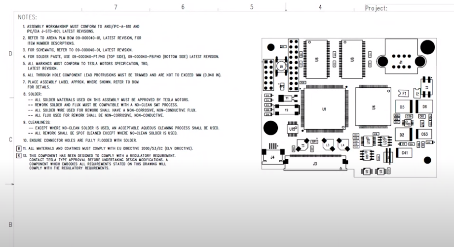
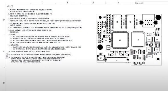
Bestückungsdruck einer Leiterplatte mit Montagehinweisen
01, LATEST REVISION, FOR ITEM NUMBER DESCRIPTIONS. 3. FOR SCHEMATIC, REFER TO 09-000040-P.PHO (TOP SIDE), 09-000040-P.PHO (BOTTOM SIDE) LATEST REVISION. 4. FOR SOLDER PASTE, USE 09-000040-P.PHO. 5. ALL MARKINGS MUST CONFORM TO TESLA MOTORS SPECIFICATION, TBD, LATEST REVISION. 6. ALL THROUGH-HOLE COMPONENT
in „Altium: Drawing Layer für Assembly Instructions“ · Platinen · · Layouts
-
 Bild
Bild
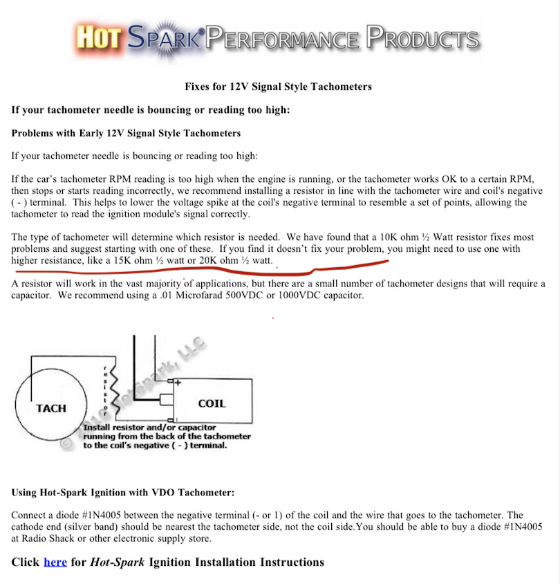
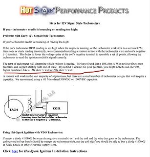
Anleitung zur Fehlerbehebung bei 12V Signal Style Tachometern
wire that goes to the tachometer. The cathode end (silver band) should be nearest the tachometer side, not the coil side. You should be able to buy a diode #1N4005 at Radio Shack or other electronic supply store. Click here for Hot-Spark Ignition Installation Instructions
in „Drehzahlmesser Impuls“ · Fahrzeugelektronik · · Screenshots
-
 Bild
Bild
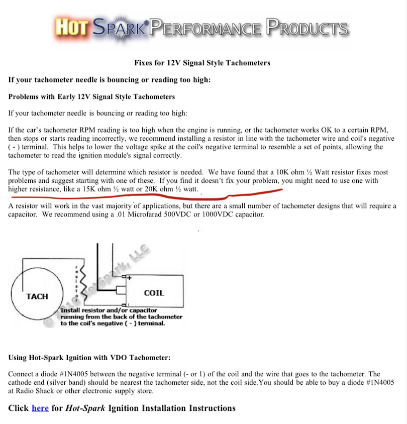
Anleitung zur Fehlerbehebung bei 12V Signal Style Tachometern
wire that goes to the tachometer. The cathode end (silver band) should be nearest the tachometer side, not the coil side. You should be able to buy a diode #1N4005 at Radio Shack or other electronic supply store. Click here for Hot-Spark Ignition Installation Instructions
in „Drehzahlmesser Impuls“ · Fahrzeugelektronik · · Screenshots
-
 Bild
Bild
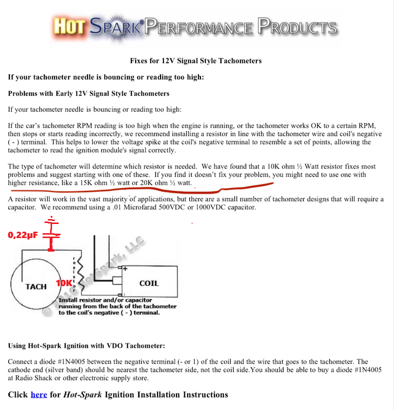
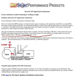
Anleitung zur Fehlerbehebung bei 12V Signal Style Tachometern
wire that goes to the tachometer. The cathode end (silver band) should be nearest the tachometer side, not the coil side. You should be able to buy a diode #1N4005 at Radio Shack or other electronic supply store. Click here for Hot-Spark Ignition Installation Instructions
in „Drehzahlmesser Impuls“ · Fahrzeugelektronik · · Diagramme
-
PDF
pamona_6490.pdf
that are not easily accessible. Thin body style allows an unlimited number of clips to be stacked side by side. Maximum frequency is 100 MHz. MATERIALS: Leads: Music Wire Tip Tubing: Insulated Stainless Steel Body: Nylon Flying Lead connection: Gold plated copper RATINGS: Operating Voltage: Hands free
-
PDF
PT4121-PowTech.pdf
Adjustable Constant LED Current current. Typical 3% output current accuracy The PT4121 includes a high-side output current High-Side Current Sense sense circuit, which uses an external resistor t seHysteretic Control: No need compensation the nominal average output current, and a Inherent CSopen protection
in „LED Scheinwerfer: Bauteil gesucht“ · Fahrzeugelektronik ·
-
PDF
PT4121-PowTech.pdf
Adjustable Constant LED Current current. Typical 3% output current accuracy The PT4121 includes a high-side output current High-Side Current Sense sense circuit, which uses an external resistor t seHysteretic Control: No need compensation the nominal average output current, and a Inherent CSopen protection
in „LED Scheinwerfer: Bauteil gesucht“ · Fahrzeugelektronik ·
-
PDF
LTC6802-1.pdf
highsideportofthebottomdevicetothelowsideportof VSENSE + thetopdevice.Withthisarrangement,themasterwritesto (WRITE) – LOW SIDE PORT orreadsfromthecascadeddevicesasiftheyformedone ON HIGHER DEVICE long shift register. The LTC6802-1 translates the voltage READ 1 level of the signals between the low side and high side ports to
in „SPI: kein SCK bei Receive - Warum?“ · Mikrocontroller und Digitale Elektronik ·
-
PDF
TDA8924.pdf
block and driver circuits for automatically in the mute mode for approximately 150 ms both the high side and low side. In this way a level shift is before switching to the operating mode (see Fig.4). performed from the low power digital PWM signal (at logic During this time, the coupling capacitors at
in „Schaltregler 24V/15A gesucht“ · Analoge Elektronik und Schaltungstechnik ·
-
PDF
Fully-Differential_Amplifiers_TI_PAPERS.pdf
input differential pair. In a standard operational amplifier, output current is taken from only one side of the input differential pair and used to develop a single-ended output voltage. In a fully-differential amplifier, currents from both sides are used to develop voltages at the high-impedance nodes
in „Frage bezüglich einer Analog-Schaltung“ · Analoge Elektronik und Schaltungstechnik ·
-
PDF
10_.pdf
Other Components Pay attention to the following items, when mounting other components on the back side of the board after capacitors have been mounted on the opposite side. When the bottom dead point of the suction nozzle is set too low, board deflection stress may be applied to the capacitors on the back side (bottom side), and cracks may occur in the capacitors. · After the board is straightened, set the bottom dead point of the nozzle on the upper surface of the board. · Periodically check and adjust the
in „Woher Eingangsschwingung am Buck“ · Analoge Elektronik und Schaltungstechnik ·
-
PDF
DOC1619.PDF
environment (emission). Traditionally, the only government regulations have been on the emission side: An electronic device is not allowed to emit more than a certain amount of radio frequency energy to avoid disturbing radio communication or operation of other electronic equip- ment. Most countries
in „Spannungsstabilisierung/Entstörung“ · Analoge Elektronik und Schaltungstechnik ·