-
Datei
Fleury_lcd_pollin.c
#define DDR(x) (*(&x - 1)) /* address of data direction register of port x */ #if defined(__AVR_ATmega64__) || defined(__AVR_ATmega128__) /* on ATmega64/128 PINF is on port 0x00 and not 0x60 */ #define PIN(x) ( &PORTF==&(x) ? _SFR_IO8(0x00) : (*(&x - 2)) ) #else #define PIN(x) (*(&x - 2)) /* address
in „LCD HD44780 mit Atmega32 ansteuern“ · Mikrocontroller und Digitale Elektronik ·
-
Datei
lcd_new.c
#define DDR(x) (*(&x - 1)) /* address of data direction register of port x */ #if defined(__AVR_ATmega64__) || defined(__AVR_ATmega128__) /* on ATmega64/128 PINF is on port 0x00 and not 0x60 */ #define PIN(x) ( &PORTF==&(x) ? _SFR_IO8(0x00) : (*(&x - 2)) ) #else #define PIN(x) (*(&x - 2)) /* address
in „HD44780 on Atmega32 with Peter Fleurys library“ · µC & Digital Electronics ·
-
PDF
SCHALTUNG_SEISMOGRAPH.pdf
Seismograph BMA020 ATmega8 DOG-LCD 128 x 64 l p T D U a u I G E U BMA020-MODUL L A 5V S S 2 2 2 2 2 9 x 1µ S K I O D 1k 3,3V 10µ 10µ C S S S G 1k 1k 1k 3,3V 4S 39T 30 3L 36i 35 32 33D 32 3P 30N 2P 28P 2N 2D 25 24 23 22 21 C
in „Seismograph selber bauen Eigenbau BMA020 DOG-LCD ATmega8 Assembler“ · Projekte & Code ·
-
Datei
main.c
Statusbericht. //---------------------------------------------------------------------- // Prozessor : ATmega88 // Takt : 1MHz, intern (TODO: verkleiner um Strom zu sparen) // Frequenz : 434MHz // Datenrate : 4.8kbps // Datum : 14.10.2015 // Version : 1.1 // Autor : P. Fuhsy // Fuses : exfuse=0xF9, hfuse=0xD7
in „Attiny13 spring t aus Hauptschleife“ · Mikrocontroller und Digitale Elektronik ·
-
Datei
Bruno_Timer1_Pulsformen.ino
/* IDE 1.8.19 auf Arduino Mega2560 getestet für Arduino Leonardo ATmega32U4 23.04.2023 https://www.mikrocontroller.net/topic/553491#7395414 */ // Auf ATmega32U4 ist PB6 Arduino Pin 10 // const uint8_t pinPulsOut {12}; // OC1B bzw. PB6 invertiert const uint8_t ANZAHLTASTER {4}; const uint8_t ANZAHLPULSFORM {ANZAHLTASTER+1}; // wegen Default Dummy Pulsform const bool DEBUG {false}; const bool DEBUGTASTER {true}; const byte pinTaster [ANZAHLTASTER] {2, 3,
in „Präzise Pulse aus Arduino Leonardo“ · Mikrocontroller und Digitale Elektronik ·
-
Datei
pins_arduino.h
D16 (SCL) (ICP1) D14 PD6 20| |21 PD7 D15 (OC2) +--------+ */ const static uint8_t SDA = 8; const static uint8_t SCL = 9; const static uint8_t SS = 4; const static uint8_t MOSI = 5; const static uint8_t MISO = 6; const static uint8_t SCK = 7; #define NUM_DIGITAL_PINS 32 #define NUM_ANALOG_INPUTS 8 #define analogInputToDigitalPin(p) ((p < 8) ? (p) + 24 : -1) #define digitalPinHasPWM(p) ((p) == 4 || (p) == 5 || (p) == 7) #ifdef ARDUINO_MAIN const uint16_t PROGMEM port_to_mode_PGM[] = { NOT_A_PORT
in „Arduino IDE mit Atmega32 - AD Wandler sind nicht benutzbar“ · Mikrocontroller und Digitale Elektronik ·
-
Datei
compiler_output.txt
avr-gcc -v -g -Wall -O2 -mmcu=atmega32 -mshort-calls -c -o main.o main.c Reading specs from C:\WinAVR\bin\..\lib\gcc-lib\avr\3.3.2\specs Configured with: ../gcc-3.3.2/configure --prefix=e:/avrdev/install --host=mingw3 2 --build=mingw32
in „Error bei Divisionen mit AVR (__udivmodqi4)“ · Mikrocontroller und Digitale Elektronik ·
-
Datei
lcd.c
#define DDR(x) (*(&x - 1)) /* address of data direction register of port x */ #if defined(__AVR_ATmega64__) || defined(__AVR_ATmega128__) /* on ATmega64/128 PINF is on port 0x00 and not 0x60 */ #define PIN(x) ( &PORTF==&(x) ? _SFR_IO8(0x00) : (*(&x - 2)) ) #else #define PIN(x) (*(&x - 2)) /* address
in „Display geht immernoch nicht.“ · Mikrocontroller und Digitale Elektronik ·
-
 Bild
Bild
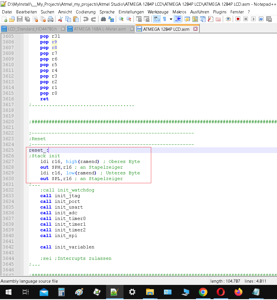
Assembly-Quellcode für ATmega 1284P
D:\MyInstall\_My_Projects\Atmel_my_projects\Atmel STUDIO\ATMEGA 1284P LCD\ATMEGA 1284P LCD\ATMEGA 1284P LCD.asm - Notepad++ pop r31 pop r9 pop r8 pop r7 pop r6 pop r5 pop r4 pop r3 pop r2 pop r1 pop r0 ret ;Reset_ ;Stack init ldi r16, high(ramend) out SPH, r16
in „Assembler-Verständnisproblem beim attiny13a“ · Mikrocontroller und Digitale Elektronik · · Screenshots
-
PDF
Timer_1_Fast_Mode_erklaert.pdf
Takt ) - 1 Mit Prescaler 64 erhalten wir: 2499 … etwas wenig für einen 16 Bit Counter Mit Prescaler 8 erhalten wir: 19999 … schon besser Mit Prescaler 1 erhalten wir: 159999 … zu viel, 16 Bit geht nur bis 65535 Also nehmen wir den Prescaler 8 und TOP Wert 19999. Damit taktet der Timer schon einmal mit
in „Timer Arduino Einsatzgebiete“ · Mikrocontroller und Digitale Elektronik ·
-
 Bild
Bild
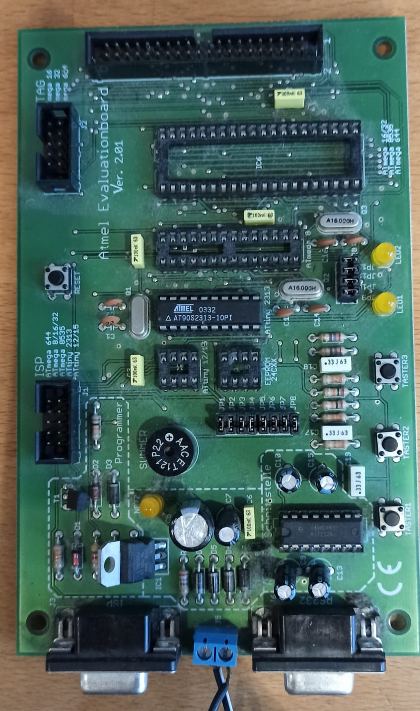
Atmel Evaluationboard Ver. 2.01 Leiterplatte
Atmel Evaluationboard Ver. 2.01 TAG ATmega 8/32 64 128 ISP ATmega 8/32 128/256 AT90S2313-10PI P22 AAC E121 PROGRAMMER ISP RS232
in „(V) Testboard“ · Markt · · Platinenfotos
-
Datei
GccApplication2.c
recevied value on the * LEDs connected to PC0..5. */ typedef union { uint32_t value32; struct { uint8_t ll; uint8_t lh; uint8_t hl; uint8_t hh; } value8; } sint32; #define nop() __asm__ __volatile__ ("nop" ::) uint8_t mmc_cmd ( uint8_t *cmd ) { uint8_t tmp = 0x80; uint8_t i = 10; for ( uint8_t a = 0;
in „SDCard, Widerstands-Level-Converter, Speed?“ · Mikrocontroller und Digitale Elektronik ·
-
Datei
main.h
Flämig on 22.08.10. * Copyright 2010 __MyCompanyName__. All rights reserved. * */ #ifndef __AVR_ATmega2560__ #define __AVR_ATmega2560__ #include <avr/io.h> #include <util/delay.h> #include <avr/interrupt.h> #define bitand & #define bitor | #define toggle ^ #define and && #define or || #define BIT0 1
in „[AVR] (ext) Interrupt aktivieren?“ · Mikrocontroller und Digitale Elektronik ·
-
PDF
AVR042_Hardware_Design_Considerations_doc2521.pdf
located on the same pins as the SPI interface. However, there are exceptions from this rule, e.g. the ATmega103 and the ATmega128 do not have the ISP lines on the SPI lines. In this case the UART lines are used for the ISP interface. Common for the ISP interfaces on all devices is that the AVR acts as a SPI
in „Atmega 8A PU“ · Mikrocontroller und Digitale Elektronik ·
-
PDF
Blockdiagramm.pdf
Blockdiagramm Michis_AVR_Dev_Kit USB/UART ICSP JTAG ICSP PC7:0 595 CH340 UART0 PB7:0 8-bit DIP PG1 UART1 Atmega328 PD3 Heartbeat Heartbeat AREF PC7:0 PF0 LCD Atmega128 DRV5033 PA7:0 I²C MAX520 Pinheader LM4040 + Buffer WS2812 PG0 PB7:0 CAT5259 PG4 ADS7828 RV4162 Backup Battery ICSP M24C64 JTAG PF7:0 AREF PG4 RS232/UART UART0 I²C MAX520 LM4040 + MAX3232 Buffer Atmega128L PCF8563 Backup Battery PA7:0 M24C64 EC11 Taster PC7:0 LCD SPI Heartbeat PG1 WS2812 PG0 ADS7844
in „Dev-Kit machen?“ · Mikrocontroller und Digitale Elektronik ·
-
Datei
PULL_UP.asm
; ; Interne PULL-UP-WIDERSTÄNDE der Eingänge aktivieren ; Bernhard.Erfurt@gmx.de ; 03/2006 ; ATmega8 .include "m8def.inc" ; REGISTER definieren .def temp = R16 .cseg ;Beginn eines Code-Segmentes .org 0 ;Startadresse=0 ; Interrupt-Vektoren für ATmega 8 rjmp RESET ; Reset Handler reti ;rjmp EXT_INT0
in „PULL-UP der Eingänge aktivieren Beispiel (Assembler) ATmega“ · Projekte & Code ·
-
PDF
FacharbeitsDocument.pdf
externen Interrupts und deren Hierachie ist in jedem Datenblatt eines μC vermerkt ( vgl. Datenblatt: AtMega 8, Atmel; S.46 Tabelle 18 ). 2.4.5 Timer Neben Interrupts besitzen μC auch ein oder mehrere Timer. Dieser ermöglicht dem μC einen Zeitraum exakt zu bestimmen. Die AVRs besitzen je nach Typ zwei unterschiedliche
in „Lichtschranke und Optokoppler an ATMEGA 8“ · Mikrocontroller und Digitale Elektronik ·
-
PDF
Hausbus_for_everyone.pdf
grundsätzlich. Das heißt, der ATMega befindet sich im sleep Zustand. Er wird nur geweckt, wenn er gebraucht wird. Mit einem Interrupt an der UART oder mit einem Interrupt von einem Sensor (Taster, ...). 3.4. Stromversorgung Die Stromversorgung
-
Datei
pins_arduino.h
D16 (SCL) (ICP1) D14 PD6 20| |21 PD7 D15 (OC2) +--------+ */ // Mapping SPI Pins const static uint8_t SDA = 8; const static uint8_t SCL = 9; const static uint8_t SS = 4; const static uint8_t MOSI = 5; const static uint8_t MISO = 6; const static uint8_t SCK = 7; // Mapping of analog pins as digital I/O static const uint8_t A0 = 24; static const uint8_t A1 = 25; static const uint8_t A2 = 26; static const uint8_t A3 = 27; static const uint8_t A4 = 28; static const uint8_t A5 = 29; static const uint8_t A6 = 30; static const
in „Arduino IDE mit Atmega32 - AD Wandler sind nicht benutzbar“ · Mikrocontroller und Digitale Elektronik ·
-
Datei
pins_arduino.h
D16 (SCL) (ICP1) D14 PD6 20| |21 PD7 D15 (OC2) +--------+ */ // Mapping SPI Pins const static uint8_t SDA = 8; const static uint8_t SCL = 9; const static uint8_t SS = 4; const static uint8_t MOSI = 5; const static uint8_t MISO = 6; const static uint8_t SCK = 7; // Mapping of analog pins as digital I/O static const uint8_t A0 = 7; static const uint8_t A1 = 6; static const uint8_t A2 = 5; static const uint8_t A3 = 4; static const uint8_t A4 = 3; static const uint8_t A5 = 2; static const uint8_t A6 = 1; static const uint8
in „Arduino IDE mit Atmega32 - AD Wandler sind nicht benutzbar“ · Mikrocontroller und Digitale Elektronik ·
-
Datei
AVR8_PowerSave_RTC_WDT.txt
Stromaufnahme Power-save/down bei AVR8 SLdt 220927 Disclaimer: none. Sue me. RTC: Power-save asynchroner Timer mit 32 KiHz-Quarz PIT WDT: Power-down Watchdogtimer 220927 17 °C 220929 uC U [V] I [uA] I [uA] t [s] RTC WDT WDT 4 s ATmega168-20PI 0452 5.0 6.13 6.35 3.3 4.42 4.46 3.0 4.24 4.26 2.0 3.33 3.77 ATmega168PA-PU 1703 5.0 1.08 6.16 4.48 3.3 0.82 4.44 3.0 0.78 4.27 2.0 0.67 3.86 4.38 ATmega328P-PU 1545 5.0 1.35 6.31 4.13 3.3 1.02 4.66 3.0 0.97 4.49 4.08 2.0 0.82 4.09 4.02
in „Atmega328p Power_Save“ · Mikrocontroller und Digitale Elektronik ·
-
Datei
xnutboot.c
be written into the baudrate register. Consult your * AVR data sheet for the correct value. On an ATmega128 running at * 14.7456 MHz a value of 7 will result in 115200 bps. */ #define BAUDRATE_FACTOR 7 /* * Maximum number of consecutive protocol errors until we give up. */ #define MAX_PROTO_ERRORS 10
in „AVR Bootloader (Basis: xnutboot) Problem bei Programmübertragung“ · Mikrocontroller und Digitale Elektronik ·
-
Datei
xnutboot.c
be written into the baudrate register. Consult your * AVR data sheet for the correct value. On an ATmega128 running at * 14.7456 MHz a value of 7 will result in 115200 bps. */ #define BAUDRATE_FACTOR 7 /* * Maximum number of consecutive protocol errors until we give up. */ #define MAX_PROTO_ERRORS 10
in „CRC-16 Implementierung unverständlich“ · Mikrocontroller und Digitale Elektronik ·
-
Datei
xnutboot.c
be written into the baudrate register. Consult your * AVR data sheet for the correct value. On an ATmega128 running at * 14.7456 MHz a value of 7 will result in 115200 bps. */ #define BAUDRATE_FACTOR 7 /* * Maximum number of consecutive protocol errors until we give up. */ #define MAX_PROTO_ERRORS 10
in „Zeitproblem beim AVR-Flashen via XMODEM“ · Mikrocontroller und Digitale Elektronik ·
-
Datei
xnutboot_1281.c
be written into the baudrate register. Consult your * AVR data sheet for the correct value. On an ATmega128 running at * 14.7456 MHz a value of 7 will result in 115200 bps. */ #define BAUDRATE_FACTOR 25 /* * Maximum number of consecutive protocol errors until we give up. */ #define MAX_PROTO_ERRORS 10
in „Zeitproblem beim AVR-Flashen via XMODEM“ · Mikrocontroller und Digitale Elektronik ·
-
Datei
Drehgeber_per_interrupt.ino
char ergebnis_str[MAX_STELLEN+1]; // funktionen zur ser. Datenausgabe void init_serio0(void) { uint8_t temp; UCSR0B = 0x0; // alles abschalten UCSR0C = BIT(UCSZ01) | BIT(UCSZ00); // default wie nach reset 8 Bit, async, no par. UBRR0=((F_CPU/16L/(DEF_BAUDRATE/10L)+5L)/10L) - 1; // passend gerundet UCSR0B
in „Drehgeber per Interrupt auswerten, AVR“ · Projekte & Code ·
-
Datei
LCD_Display_Test.txt
//////////////// // Schreibt ein Zeichen in den Character Generator RAM void lcd_generatechar( uint8_t code, const uint8_t *data ) { // Startposition des Zeichens einstellen lcd_command( LCD_SET_CGADR | (code<<3) ); // Bitmuster übertragen for ( uint8_t i=0; i<8; i++ ) { lcd_data( data[i] ); } } // // Anpassungen im makefile: // ATMega8 => MCU=atmega8 im makefile einstellen // lcd-routines.c in SRC = ... Zeile anhängen // #include <avr/io.h> int main(void) { // Initialisierung des LCD // Nach der Initialisierung müssen auf dem LCD
in „Problem mit der Steuerung eines LCD-Displays“ · Mikrocontroller und Digitale Elektronik ·
-
Datei
LCD_Display_Test.c
//////////////// // Schreibt ein Zeichen in den Character Generator RAM void lcd_generatechar( uint8_t code, const uint8_t *data ) { // Startposition des Zeichens einstellen lcd_command( LCD_SET_CGADR | (code<<3) ); // Bitmuster übertragen for ( uint8_t i=0; i<8; i++ ) { lcd_data( data[i] ); } } // // Anpassungen im makefile: // ATMega8 => MCU=atmega8 im makefile einstellen // lcd-routines.c in SRC = ... Zeile anhängen // #include <avr/io.h> int main(void) { // Initialisierung des LCD // Nach der Initialisierung müssen auf dem LCD
in „Problem mit der Steuerung eines LCD-Displays“ · Mikrocontroller und Digitale Elektronik ·
-
Datei
Hauptprogramm.txt
// // Anpassungen im makefile: // ATMega8 => MCU=atmega8 im makefile einstellen // lcd-routines.c in SRC = ... Zeile anhängen // #include <avr/io.h> #include "lcd-routines.h" int main(void) { lcd_init(); lcd_data('T'); lcd_data('e'); lcd_data
in „LCD geht nicht, ich Bitte um hilfe“ · Mikrocontroller und Digitale Elektronik ·
-
Datei
spi_low_level.h
ll_bitbang_write ( u8 d // const u8* buff, /* Data to be sent */ // u16 bc /* Number of bytes to send */ ) { // u8 d; // do { // d = *buff++; if (d & 0x80)ll_mosi_checked; else ll_mosi_unchecked; // bit7 ll_ck_cycle; if (
in „TFT_ILI9163C mit Arduino richtig verbinden“ · Mikrocontroller und Digitale Elektronik ·
-
Datei
Sd2Card.h
type_;} uint8_t writeBlock(uint32_t blockNumber, const uint8_t* src); uint8_t writeData(const uint8_t* src); uint8_t writeStart(uint32_t blockNumber, uint32_t eraseCount); uint8_t writeStop(void); private: uint32_t block_; uint8_t chipSelectPin_; uint8_t errorCode_; uint8_t inBlock_; uint16_t offset_; uint8_t partialBlockRead_; uint8_t status_; uint8_t type_; // private functions uint8_t cardAcmd(uint8_t cmd, uint32_t arg) {
in „SD Karte an AVR 328 Arduino UNO welche Pins ?“ · Mikrocontroller und Digitale Elektronik ·
-
Datei
uart.h
int baudrate); /** @brief Get received byte of USART1 from ringbuffer. (only available on selected ATmega) @see uart_getc */ extern unsigned int uart2_getc(void); /** @brief Put byte to ringbuffer for transmitting via USART1 (only available on selected ATmega) @see uart_putc */ extern void uart2_putc(unsigned
in „TTL Signal Verarbeitung“ · Mikrocontroller und Digitale Elektronik ·
-
Datei
Auftrag_Franz.asm
******************************************************************* ;* * ;* Zufallsgenerator mit Atmega 8515 * ;* * ;******************************************************************************** ;* * ;* Autor : Sven Löffler * ;* * ;* Version : 1.0 * ;* * ;* Datum : 23.03.2009 * ;* * ;*************
in „Einfacher Zufallsgenerator“ · Mikrocontroller und Digitale Elektronik ·
-
Datei
empfaenger.asm
--------------------------------------------------------------------- ;| Title : Grundgerüst für ATmega8 ;+---------------------------------------------------------------------- ;| Funktion : ... ;| Schaltung : ... ;+---------------------------------------------------------------------- ;| Prozessor : ATmega8 ;| Takt : 3,6864 MHz ;| Sprache : Assembler ;| Datum : ... ;| Version : ... ;| Autor : Joachim Haß ;+---------------------------------------------------------------------- .include "m8def.inc" ;+-
in „Empfänger- Servosignal mit Atmega 8 auswerten“ · Mikrocontroller und Digitale Elektronik ·
-
Datei
main.c
/************************************************************** Verdrahtung: ATMega16 --> L3G4200D MISO(Master) PB6 [Eingang ] --> MISO(Slave) SDO [Ausgang] MOSI(Master) PB5 [Ausgang ] --> MOSI(Slave) SDA [Eingang] SCK (Master) PB7 [Ausgang High] --> SCK (Slave) SCL [Eingang] PB0
in „Interrupt + Timer + LCD“ · Mikrocontroller und Digitale Elektronik ·
-
Datei
ASM_SourceRUN.txt
--------------------------------------------------------------- ;| Title : myAVR Grundgerüst für ATmega8 ;+---------------------------------------------------------------------- ;| Funktion : ... ;| Schaltung : ... ;+---------------------------------------------------------------------- ;| Prozessor : ATmega8 ;| Takt : 3,6864 MHz ;| Sprache : Assembler ;| Datum : ... ;| Version : ... ;| Autor : ... ;+---------------------------------------------------------------------- .include "AVR.H" ;.include "m8def.inc
in „ADC-Input und Auswahlverfahren“ · Mikrocontroller und Digitale Elektronik ·
-
Datei
main.c
//* LED fading test //* uses exponential PWM settings to achive visual linear brightness //* //* ATmega32 @ 8 MHz //* //* //***************************************************************************** #ifndef F_CPU /* In neueren Version der WinAVR/Mfile Makefile-Vorlage kann F_CPU im Makefile definiert
in „ATMega32 USART 16MHz (Pollin-Board)“ · Mikrocontroller und Digitale Elektronik ·
-
PDF
AVR341.pdf
change is triggered. 3.5 Connecting the touch screen to the AVR The implementation example uses the ATmega88 as touch screen controller (see datasheet ATmega88 for details). Figure 3-1 and Figure 3-2 illustrates how to connect the ATmega88 to respectively a 5-wire and a 4-wire touch screen. In order to
in „Anleitung eines Touch Lcd“ · Mikrocontroller und Digitale Elektronik ·
-
Datei
LCD_Programm.txt
CURSOR_HOME); _delay_ms(5); } // setzt den Cursor in Zeile y (1..4) Spalte x (0..15) void set_cursor(uint8_t x, uint8_t y) { switch (y) { case 1: lcd_command(0x80+0x00+x); break; // 1. Zeile case 2: lcd_command(0x80+0x40+x); break; // 2. Zeile case 3: lcd_command(0x80+0x10+x); break; // 3. Zeile case 4: lcd_command
in „LCD-Tutorial: einige zeilen sind unverständlich“ · Mikrocontroller und Digitale Elektronik ·
-
Datei
lcd_io1.c
zero_reg__ \n\t" \ "cpc %D0,__zero_reg__ \n\t" \ "breq L_EXIT_%= \n\t" \ "L_%=: \n\t" \ "subi %A0,lo8(-(-1)) \n\t" \ "sbci %B0,hi8(-(-1)) \n\t" \ "sbci %C0,hlo8(-(-1)) \n\t" \ "sbci %D0,hhi8(-(-1)) \n\t" \ "brne L_%= \n\t" \ "L_EXIT_%=: \n\t" \ : \ : "w" (number_of_loops) \ ); \ return; } */ static void
-
Datei
lcd_io1.c
zero_reg__ \n\t" \ "cpc %D0,__zero_reg__ \n\t" \ "breq L_EXIT_%= \n\t" \ "L_%=: \n\t" \ "subi %A0,lo8(-(-1)) \n\t" \ "sbci %B0,hi8(-(-1)) \n\t" \ "sbci %C0,hlo8(-(-1)) \n\t" \ "sbci %D0,hhi8(-(-1)) \n\t" \ "brne L_%= \n\t" \ "L_EXIT_%=: \n\t" \ : \ : "w" (number_of_loops) \ ); \ return; } */ static void
in „LCD I2C Bibliothek“ · Mikrocontroller und Digitale Elektronik ·
-
Datei
m8def.inc
" ;* Title : Register/Bit Definitions for the ATmega8 ;* Date : 2005-01-11 ;* Version : 2.14 ;* Support E-mail : avr@atmel.com ;* Target MCU : ATmega8 ;* ;* DESCRIPTION ;* When including this file in the assembly program file, all I/O register ;* names
in „Probleme mit rjmp beim AVR Atmega 8L“ · Mikrocontroller und Digitale Elektronik ·
-
Datei
m8def.inc
" ;* Title : Register/Bit Definitions for the ATmega8 ;* Date : 2011-02-09 ;* Version : 2.35 ;* Support E-mail : avr@atmel.com ;* Target MCU : ATmega8 ;* ;* DESCRIPTION ;* When including this file in the assembly program file, all I/O register ;* names
in „AVR8ASM TWI Interrupt“ · Mikrocontroller und Digitale Elektronik ·
-
Datei
m8def.inc
" ;* Title : Register/Bit Definitions for the ATmega8 ;* Date : 2011-02-09 ;* Version : 2.35 ;* Support E-mail : avr@atmel.com ;* Target MCU : ATmega8 ;* ;* DESCRIPTION ;* When including this file in the assembly program file, all I/O register ;* names
in „AVR8ASM TWI Interrupt“ · Mikrocontroller und Digitale Elektronik ·
-
Datei
m8def.inc
" ;* Title : Register/Bit Definitions for the ATmega8 ;* Date : 2011-02-09 ;* Version : 2.35 ;* Support E-mail : avr@atmel.com ;* Target MCU : ATmega8 ;* ;* DESCRIPTION ;* When including this file in the assembly program file, all I/O register ;* names
in „AVR8ASM TWI Interrupt“ · Mikrocontroller und Digitale Elektronik ·
-
Datei
m8def.inc
" ;* Title : Register/Bit Definitions for the ATmega8 ;* Date : 2011-02-09 ;* Version : 2.35 ;* Support E-mail : avr@atmel.com ;* Target MCU : ATmega8 ;* ;* DESCRIPTION ;* When including this file in the assembly program file, all I/O register ;* names
in „AVR8ASM TWI Interrupt“ · Mikrocontroller und Digitale Elektronik ·
-
Datei
m8def.inc
" ;* Title : Register/Bit Definitions for the ATmega8 ;* Date : 2011-02-09 ;* Version : 2.35 ;* Support E-mail : avr@atmel.com ;* Target MCU : ATmega8 ;* ;* DESCRIPTION ;* When including this file in the assembly program file, all I/O register ;* names
in „AVR8ASM TWI Interrupt“ · Mikrocontroller und Digitale Elektronik ·
-
Datei
m8def.inc
" ;* Title : Register/Bit Definitions for the ATmega8 ;* Date : 2011-08-25 ;* Version : 2.35 ;* Support E-mail : avr@atmel.com ;* Target MCU : ATmega8 ;* ;* DESCRIPTION ;* When including this file in the assembly program file, all I/O register ;* names
in „AVR-Mikrocontrollertechnik-Kursus in Assembler besprechung“ · Mikrocontroller und Digitale Elektronik ·
-
Datei
m8def.inc
" ;* Title : Register/Bit Definitions for the ATmega8 ;* Date : 2011-08-25 ;* Version : 2.35 ;* Support E-mail : avr@atmel.com ;* Target MCU : ATmega8 ;* ;* DESCRIPTION ;* When including this file in the assembly program file, all I/O register ;* names
in „AVR-Mikrocontrollertechnik-Kursus in Assembler besprechung“ · Mikrocontroller und Digitale Elektronik ·
-
Datei
main.c
// // Anpassungen im makefile: // ATMega8 => MCU=atmega8 im makefile einstellen // lcd-routines.c in SRC = ... Zeile anhängen // #include <avr/io.h> #include <stdio.h> #include <stdlib.h> #include <string.h> #include "main.h" #include "lcd.h
in „LCD tc1604a mit ATMEGA16“ · Mikrocontroller und Digitale Elektronik ·