-
Thread
Regelverhalten Labornetzgerät
Gerhard O. schrieb im Beitrag #7794392: > Normalerweise sollte die Ausregelzeit innerhalb von 50-100us liegen. > > Im Handbuch sollte die Ausregelzeit in den Specifications angegeben > sein. > Im Handbuch steht: Regelverhalten bei Laständerung 0 ~ 100%: <= 25 mV/ <= 10 mA
Gerhard O. schrieb im Beitrag #7794392: > Normalerweise sollte die Ausregelzeit innerhalb von 50-100us liegen. Das wäre für Billignetzteile ziemlich gut. Eher 1ms.
-
 Bild
Bestellhistorie eines Online-Shops
Bestellung aufgegeben am: 16. Jan 2021 Bestellnummer: 3008 Ultisolar Controller&Sensors Wholesale Branch US211M Lite Digitale Durchflussmesser und USN-HS41PE-2 0,2-2,5 LPM... Gesamt 1,79€ In den Warenkorb Löschen Abgeschlossen Bestellung aufgegeben am: 13. Jan 2021 Bestellnummer: 3008 DIGITEN Official Store
-
 Bild
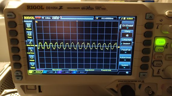
Abfotografiertes Rigol DS1054Z Oszilloskop mit Sinuswelle
RIGOL DS1054Z OSCILLOSCOPE UltraVision 4 Channel 50MHz 1GSa/s MENU STOP 2.00us 10.0MSa/s 8.00M pts D 910.40000ms Horizontal Period Rise Time Full Time -Width +Width Vpp=58.0mV Max=28.0mV Pulses=14 1=50.0mV 2=1.00V 3=1.00V 4=20.0V EA Einstell Klang Deutsch Pass/Fail Aufzeichnen System Intensity CH1 CH2 CH3 CH4
-
 Bild
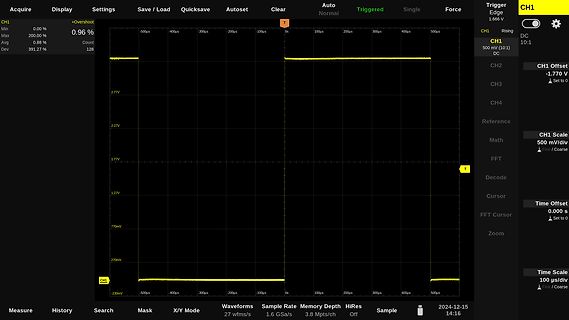
Oszilloskop-Screenshot einer Rechteckschwingung
Acquire Display Settings Save / Load Quicksave Autoset Clear Auto Normal Triggered Single Force CH1 +Overshoot Min 0.00 % Max 0.96 % Avg 0.88 % Dev 391.27 % -500us -400us -300us -200us -100us 0s 100us 200us 300us 400us 500us 2.77V 2.27V 1.77V 1.27V 770mV 270mV -230mV CH1 Trigger Edge 1.666 V CH1 Rising DC 10:1 500 mV/div DC CH2 CH3 CH4 Reference Math FFT Decode Cursor Time Offset 0.000 s FFT Cursor Zoom Time Scale 100 us/div Coarse Measure History Search Mask X/Y Mode Waveforms Sample Rate Memory Depth HiRes
-
Thread
Mikrocontroller Einstieg
last iteration): (N-1) * (1 + 2) cycles = 3N - 3 cycles For the last iteration of the inner loop: 1 + 1 = 2 cycles For each complete outer loop (except the last iteration): (M-1) * (3N - 1) cycles For the last iteration of the outer loop: 3N + 1 cycles Finally, we add the return instruction: 4 cycles Therefore, the total number of cycles can be calculated as: Total cycles = (M-1) * (3N - 1) + (3N + 1) + 4 This simplifies to: Total
-
 Bild
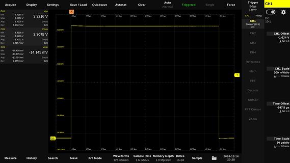
Oszilloskop-Screenshot einer Messung
Acquire Display Settings Save / Load Quicksave Autoset Clear Auto Normal Triggered Single Force CH1 Edge DC 10:1 CH1 500 mV/div DC CH1 Offset -1.634 V Set to 0 CH2 CH3 CH4 Reference CH1 Scale 500 mV/div Fine / Coarse Math Decode Cursor Time Offset -247.5 us Set to 0 FFT FFT Cursor Zoom Time Scale 50 us/div Coarse Fine CH1 3.3216 V Max 3.3209 V Min 3.3075 V Avg 3.3108 V Dev 128 Count -14.145 mV Max -10.895 mV Min -13.754 mV Dev 4.3559 mV Count 128 Measure History Search Mask X/Y Mode Waveforms Sample
-
Thread
Kondenswasser-Menge erfassen
Leitungswasser, weil es besser schmeckt, als Osmosewasser und das Zeug von Lidl oder Penny oder netto. US211M Lite Digitale Durchflussmesser und USN-HS41PE-2 0,2-2,5 LPM Halle Wirkung Fluss Sensor Insgesamt Volumen und Fluss rate Display So ein Funk Regensensor habe ich auch vor ein paar Tagen bei Grabbeltisch
Ulli F. schrieb im Beitrag #7794056: > US211M Lite Digitale Durchflussmesser und USN-HS41PE-2 0,2-2,5 LPM Halle > Wirkung Fluss Sensor Insgesamt Volumen und Fluss rate Display Von "0.5 bis 10 Liter pro Minute" wird man bei 1 Tropfen pro
-
Thread
Verlorenen Funkschlüssel auffinden
streudy_s Vorname Streudy Nachname Streudy Firma Angemeldet seit 14.12.2024 00:23 Beiträge 1
streudy_s Vorname Streudy Nachname Streudy Firma Angemeldet seit 14.12.2024 00:23 Beiträge 1
-
 Bild
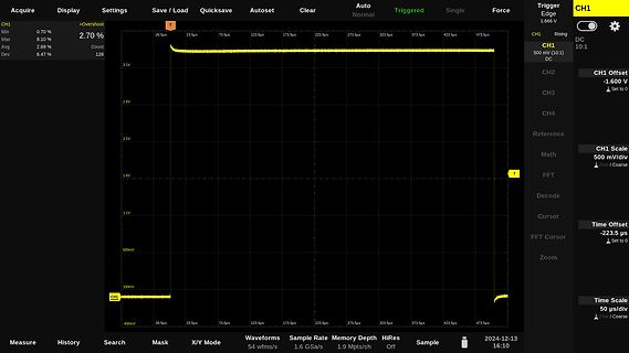
Oszilloskop-Screenshot einer Gleichspannung
Display Settings Save / Load Quicksave Autoset Clear Auto Normal Triggered Single Force Trigger Edge 1.666 V CH1 Min 0.70% Max 8.10% Avg 2.69% Dev 6.47% +Overshoot Count 128 T -26.5us 23.5us 73.5us 123.5us 173.5us 223.5us 273.5us 323.5us 373.5us 423.5us 473.5us 3.1V 2.6V 2.1V 1.6V 1.1V 600mV 100mV -400mV CH1 500 mV (10:1) DC CH1 Offset -1.600 V Set to 0 CH2 CH3 CH4 Reference CH1 Scale 500 mV/div DC Math FFT Decode Cursor Time Offset -223.5 us Set to 0 Zoom Time Scale 50 us/div Coarse Measure History Search
-
 Bild
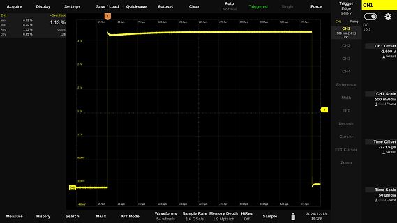
Oszilloskop-Messung einer Gleichspannung
Display Settings Save / Load Quicksave Autoset Clear Auto Normal Triggered Single Force Trigger Edge 1.666 V CH1 Rising DC CH1 500 mV (10:1) DC CH2 CH3 CH4 Reference CH1 Offset DC CH2 CH3 CH4 Reference Math 500 mV/div DC FFT Decode Cursor Time Offset -223.5 us FFT Cursor Zoom Time Scale 50 us/div Coarse CH1 Min 0.73% Max 8.10% Avg 1.12% Dev 0.85% Count 128 -26.5us 23.5us 73.5us 123.5us 173.5us 223.5us 273.5us 323.5us 373.5us 423.5us 473.5us 3.1V 2.6V 2.1V 1.6V 1.1V 600mV 100mV -400mV Measure History Search
-
 Bild
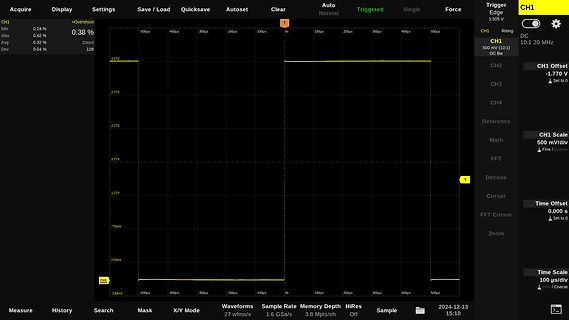
Oszilloskop-Screenshot einer Rechteckspannung
Acquire Display Settings Save / Load Quicksave Autoset Clear Auto Normal Triggered Single Force CH1 +Overshoot Min 0.24% Max 0.42% Avg 0.32% Dev 0.04% 128 Trigger Edge 1.505 V CH1 Rising DC 10:1 20 MHz CH1 500 mV (10:1) DC BW CH2 CH3 CH4 Reference CH1 Scale 500 mV/div Fine / Coarse CH2 -1.770 V Set to 0 CH3 CH4 FFT Decode Cursor Time Offset 0.000 s Set to 0 FFT Cursor Zoom Time Scale 100 us/div Fine / Coarse Measure History Search Mask X/Y Mode Waveforms 27 wfms/s 1.6 GSa/s Memory Depth 3.8 Mpts/ch HiRes Off Sample 2024-12-13 15:10
-
 Bild
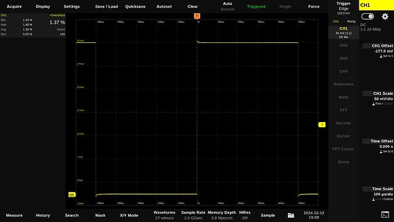
Oszilloskop-Screenshot einer Rechteckschwingung
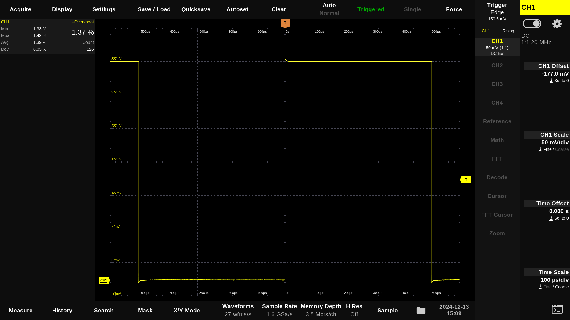
Settings Save / Load Quicksave Autoset Clear Auto Normal Triggered Single Force Trigger Edge 150.0 mV CH1 +Overshoot Min 1.33 % Max 1.48 % Avg 1.37 % Dev 0.03 % Count 126 CH1 Rising DC 1:1 20 MHz CH1 50 mV (1:1) DC Bw CH2 Offset -177.0 mV CH3 CH4 Reference CH1 Scale 50 mV/div Math Fine / Coarse FFT Decode Cursor Time Offset 0.000 s FFT Cursor Zoom Time Scale 100 us/div Fine / Coarse Measure History Search Mask X/Y Mode Waveforms 27 wfms/s Sample Rate 1.6 GSa/s Memory Depth 3.8 Mpts/ch HiRes Off Sample 2024-12-13 15:09
-
Thread
Windows 11 doch auf alten Rechnern
Festplatte installiert. HDD statt SDD. Ist ein Gigabyte Bord. https://www.reichelt.de/gigabyte-b650m-ds3h-am5--ga-b650m-49825-p355551.html?&trstct=pol_1&nbc=1 Kann mir einer sagen, wie ich ins StartMenue oder Bios komme ? Wenn ich DEL für Bios oder F12 für StartMenue drücke, bleibt die Kiste einfach
Jens M. schrieb im Beitrag #7796113: > 24H2 ist 26100, Canary sind die nächsten Betas. Das bedeutet m.M.n. das > der nächste Upgrade auf 25H1 deine Kiste zum Briefbeschwerer macht, wie > angekündigt.
-
Thread
Warum können die Chinesen PCB's so billig herstellen?
Gerald K. schrieb im Beitrag #7793010: > Aber die Rückgewinnung kostet viel Energie. 1-3 Cent/(m^2) zweiseitige Platine...
im Beitrag #7793037: > Gerald K. schrieb: >> Aber die Rückgewinnung kostet viel Energie. > > 1-3 Cent/(m^2) zweiseitige Platine... **Deutschland**: ca. 9,99 Eurocent pro m² Leiterplatte. **China**: ca. 4,8 Eurocent pro m² Leiterplatte. Grobe Schätzung von ChatGPT bei 50%-iger Entfernung
-
Thread
C++ in C-Code in Microchip Studio einbinden
Wulf D. schrieb im Beitrag #7791671: > Leider kommt der mit einem aufwändigen Timer-Interrupt von 40us(!) [code] 1.2.1 UART Interface The single wire interface allows unidirectional operation (for parameter setting only), or bi-directional operation for full control and diagnostics. It can be driven
Funktion. Irgendwo müssen die Dinge halt gemacht werden. Ein kleines Beispiel: https://godbolt.org/z/P9M4hzW1s Es werden mehrere Objekte mit Konstruktoren und templates sowie Iteratoren genutzt. Der generierte Code ist so gut wie optimal, mir fällt auf die Schnelle nichts auf was da noch besser sein könnte
-
Thread
Netzteil und Akku - 3.3V Ladeschaltung für LicheeRV Nano mit Lith.-Akku
Worum geht es? - Ich möchte einen LicheeRV Nano (https://wiki.sipeed.com/hardware/en/lichee/RV_Nano/1_intro.html#Specifications) inkl. 2,5" Touch-Display mit einem Lithium Polymer Akku betreiben (ob 1000mah ausreichen muss ich noch testen - gehen wir mal von diesem aus: https://www.amazon.de/exec/obidos
the VSYS interface is connected to the VSYS of the > PMU. If you have any questions, please contact us for support. Man muss also einen Resistor entfernen, wenn man sowas damit plant.
-
Thread
Plätzchen aus dem 3D-Drucker?
müsstest Du sie trotzdem noch selber. Mal davon abgesehen würde da jedes Laible gleich aussehen, das hat m.E. nicht viel von selber backen. ;)
aber soweit ich weiß jetzt auch pleite. Plattenküche ab 3:50 Minute: https://youtu.be/2zp73bxDzUs?si=SVPIoHV6Ibzsl_eR
-
Thread
AT90S8535 lockbits mit voltage glitch entfernen möglich?
Jens G. schrieb im Beitrag #7790392: > Woher soll diese Idee herstammen? https://youtu.be/GWSZykUsBw8?si=5LDJyeoDhgklg36Q Ich werde es bald ausprobieren. Wahrscheinlich wird es nicht funktionieren.
Lothar M. schrieb im Beitrag #7790456: > - "Copyright © 2013 Mikatech. All rights reserved." > > Das fängt ja schon gut an... Und ganz bestimmt verwenden sie die Markenzeichen der diversen Hersteller mit
-
Thread
TIP3055 - Echt oder Fälschung?
wie http://www.eag.com/locations/north-america/irvine-ca/ und bekommt in ein paar Tagen für 50 US$ den ausgeätzten Chip zurück. ...] Danke, Mawin!
ja über Reichelt schlecht geredet. Wegen Fälschungen. Die von ST hat Reichelt auch im Angebot. (1Euro) Der Preis ist natürlich verlockend. Danke Dir.
-
 Bild
Oszilloskop-Screenshot einer Rechteckwelle
Hantek STOP H 500us 500.00KSa/s 4Kpt D 0.00s sparen Arten von Bild BX-AX = -2.14ms |1/dX| = 467.29Hz AX = 1ms BX = -1.14ms schalte aus sparen Uart 1f 1f PKpk=3.36V Frequency=878.73Hz Width=1.03ms 1DC 1V 2DC 1V G 1.50Vpp 0mV B 1/1

-
 Bild
Oszilloskop-Screenshot eines Rechtecksignals
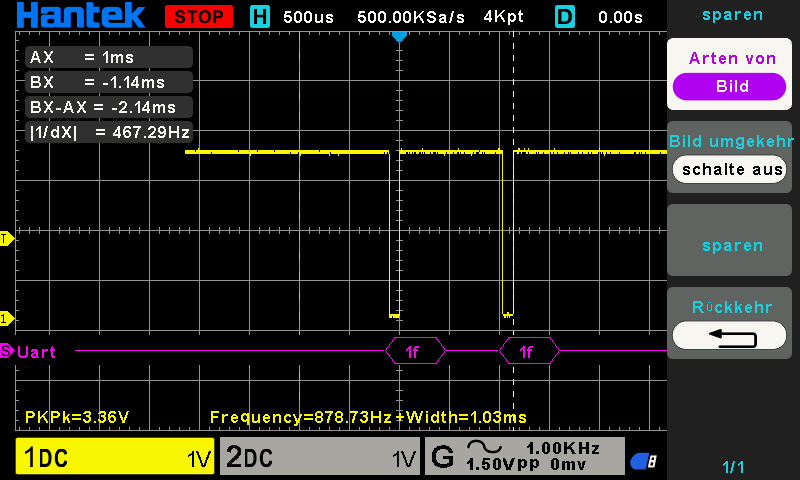
Hantek STOP H 500us 500.00KSa/s 4Kpt D 1.92ms sparen Arten von Bild umgekehrt schalte aus sparen Rückkehr AX = 1ms BX = -1ms BX-AX = -2ms |1/dX| = 500Hz Uart 1f 1f PKpk=3.36V Frequency=878.73Hz Width=1.03ms 1DC 1V 2DC 1V G 1.50Vpp 0mV 1.00KHz B 1/1

-
Thread
Raspberry Pi 500, ST-Entwicklerkongress und vieles andere mehr
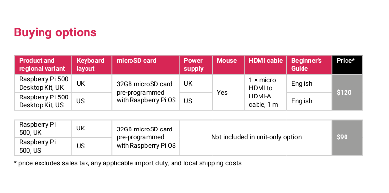
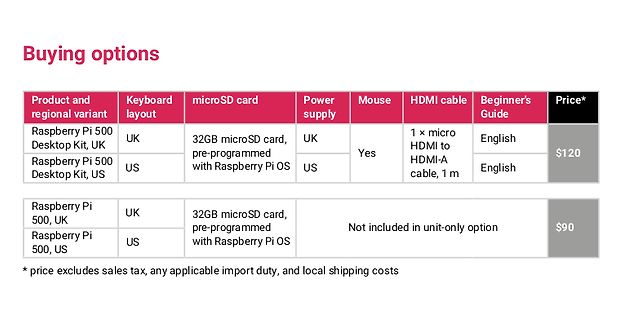
steht nun - wie in der Abbildung gezeigt - ein Nachfolge-Modell bereit.  Bildquelle: https://www.raspberrypi.com/news/raspberry-pi-500-and-raspberry-pi-monitor-on-sale-now/ Der um 90 US-Dollar erhältliche und unter der URL https://www.raspberrypi.com/products
attachment/654568/2.png) Bildquelle: https://www.raspberrypi.com/products/raspberry-pi-500/ Um 120 US-Dollar gibt es außerdem eine als „Compute Kit“ bezeichnete Variante, die neben einem Lehrbuch auch die Raspberry Pi-eigene Maus, eine Stromversorgung und ein HDMI-Kabel mit durchaus großzügigen 2 m Länge
-
 Bild
Preistabelle für Raspberry Pi 500 Kaufoptionen
Raspberry Pi 500 Desktop Kit, UK UK 32GB microSD card, pre-programmed with Raspberry Pi OS UK Yes 1 x micro HDMI to HDMI-A cable, 1 m English $120 Raspberry Pi 500 Desktop Kit, US US 32GB microSD card, pre-programmed with Raspberry Pi OS US Yes 1 x micro HDMI to HDMI-A cable, 1 m English Raspberry
-
Thread
Sonderzeichen
nicht erlaubt. [pre] $ echo blabla > 'Was zum Geier™ soll der ganze Schei*** hier eigentlich?!¬1^???' $ ls -l Was* -rw-r--r-- 1 j wheel 7 Dec 9 22:36 Was zum Geier™ soll der ganze Schei*** hier eigentlich?!¬1^??? $ rm Was* [/pre] Geht doch :-)
Musik-Sammlungen ist das ebenso gängige Praxis. Diesbezüglich habe ich gute Erfahrungen mit detox [1] gemacht. HTH, YMMV. [1] https://sourceforge.net/projects/detox/
-
Thread
stm32f411 USART2 will nicht wie er soll
rx_buff_ct; void USART2_IRQHandler_kk(void) { rx_buff[rx_buff_ct++]=USART2->DR; USART2->CR1 &= ~USART_CR1_RE; USART2->CR1 |= USART_CR1_RE;// //_delay_us(15); if(rx_buff_ct==7) { rx_buff_ct=0; lcd_goto(15,1);// lcd_int2(rx_buff[0]);// lcd_write(" "); lcd_int2(rx_buff[1])
[c] rx_buff[rx_buff_ct++]=USART2->DR; USART2->CR1 &= ~USART_CR1_RE; USART2->CR1 |= USART_CR1_RE; [/c] läuft es mit [c] rx_buff[rx_buff_ct++]=USART2->DR; USART2->CR1 &= ~(USART_CR1_RXNEIE); USART2->CR1 |= (USART_CR1_RXNEIE); [/c]
-
Thread
Arduino Nano Matter final, Einplatinencomputer mit HDMI-Eingang und andere Hardware
teilweise über einen Gowin-FPGA erfolgt. 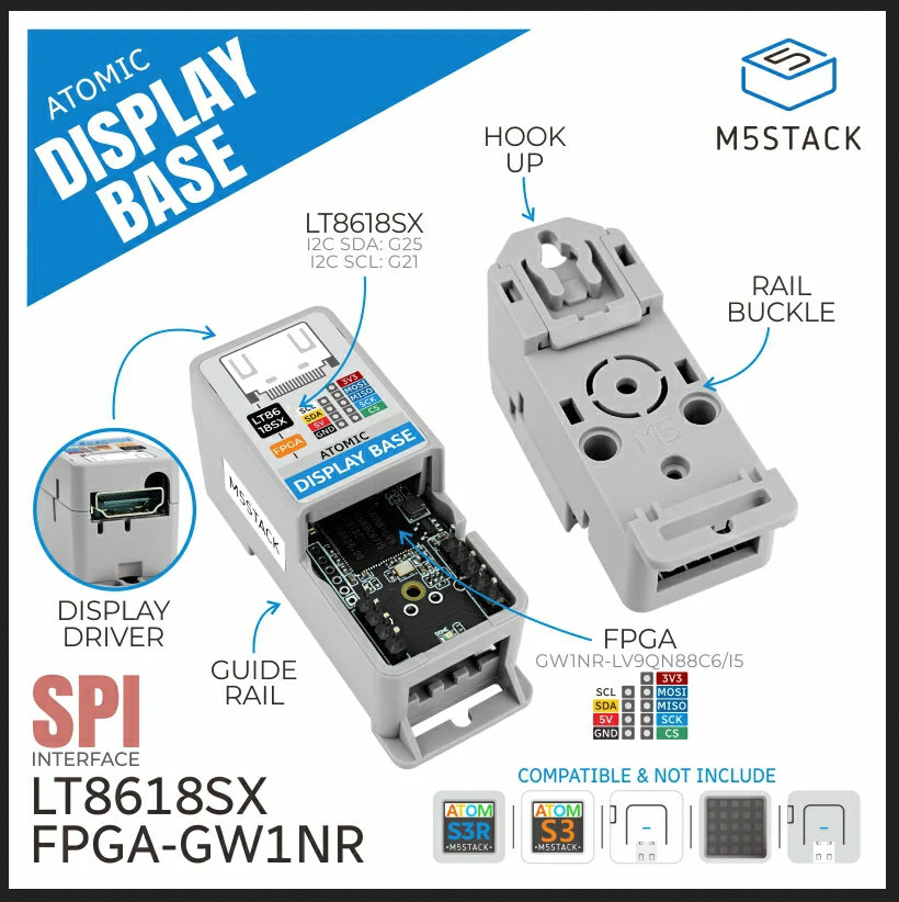 Bildquelle: https://shop.m5stack.com/products/atomic-display-base-gw1nr?variant=45727247991041 ### Steckplatinen-Stromversorgung auf Basis eines XIAO-Moduls. Im Pleistozän der Laborentwicklung - der Newsautor ist so alt
introduce two ultra-low power Wi-Fi HaLow™ modules (LBWA0ZZ2HK and LBWA0ZZ2HL) compliant with Sub-1 GHz (S1G) Wi-Fi standards across key regions, achieving high-speed communication over distances of more than 1km. The compact modules support high power at +23dBm (Type 2HK) and low power at +13dBm (
-
Thread
Anlaufstrombegrenzer für Festplatten?
Festplatten (Link: https://www.seagate.com/www-content/datasheets/pdfs/ironwolf-18tb-DS1904-20-2111US-en_US.pdf) haben diese eine durchschnittliche Leistungsaufnahme von 4,8 W. Bei 12 V wären das 0,4 A. Beim Anlaufen der HDD's wird aber ein Strom von 1,8 A gezogen ("Startup current"). Angeblich (laut diesem Beitrag: https://www.reddit.com/r/homelab/comments/1d722m5/comment/lwehdpt/?utm_source=share&utm_medium=web3x&utm_name=web3xcss&utm_term=1&utm_content=share_button) kann der 12V-Wandler des S920 aber nur 2 A bereitstellen, d.h. wenn beide Platten gleichzeitig
-
Thread
touchpad ili9341 will nicht wie es soll
); \ GPIO(port)->PUPDR|= (pullup<<(pin*2));} #define pinset(x,y) GPIO(x)->BSRR|=(1<<y) #define pinclr(x,y) GPIO(x)->BSRR|=(1<<(y+16)) #define pinget(x,y) (GPIO(x)->IDR & (1<<(y))) #define led1_port C #define led1_pin 13 #define led1_tog GPIO(led1_port)->ODR ^=(1<<led1_pin) #define led1_on GPIO(led1_port)->BSRR|=(1<<led1_pin) #define led1_off GPIO(led1_port)->BSRR|=(1<<(led1_pin+16)) [/c] aus HAL_GPIO_WritePin(GPIOC, GPIO_PIN_13, GPIO_PIN_RESET);
-
 Bild
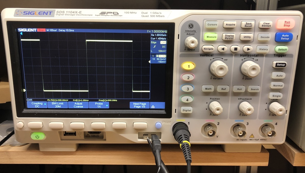
Siglent digitales Oszilloskop mit Rechtecksignal
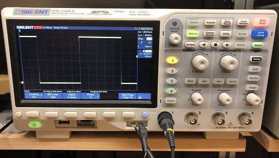
SIGLENT SDS 1104X-E 100 MHz Dual 1 GSa/s Quad 500 MSa/s Stop 100us/div Delay 10.0ms f=1.00000kHz Sa 1.00GSa/s Cur 1.40Mpts CH1 50.0mV 1X -150mV PK-PK 300.00mV PrD 1.00ms Freq 999.99Hz BW Limit 20M Coupling DC
-
 Bild
Display eines Siglent Oszilloskops mit Lizenzinformationen
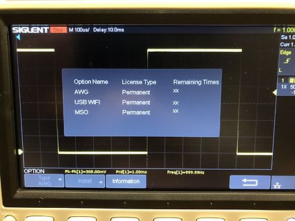
SIGLENT Stop M 100us/ Delay:10.0ms f = 1,000 Sa 1.0 Curr 1. Edge L 1X 50 Option Name License Type Remaining Times AWG Permanent XX USB WIFI Permanent XX MSO Permanent XX OPTION Pk-Pk[1]=308.00mV Prd[1]=1.00ms Freq[1]=999.99Hz Type AWG Install Information
-
Thread
Funkwellen im Bereich 2.4 GHz nachweisen, nicht messen
A4ziser-Mikrowellendetektor-Digitales-Mikrowellenleckdetektor-Strahlungsmessger%C3%A4t/dp/B09PVH84H1/ref=asc_df_B09PVH84H1
ausprobiert und ergibt an einem 100uA Meter an einer älteren Microwelle durchschnittlich 40uA in etwa 1m Entfernung. Durchschnittlich deswegen, weil scheinbar mit dem rotierenden Teller auch die Feldstärke reichlich schwankt. Dect, Fritzbox, CellPhone, oder 2m portabel usw. natürlich auch detektierbar.
-
Thread
Neue Bauteile – optische USB-Kabel, ADCs, PWM-Verstärker uvam
begegnet diesem Problem mit der AO-Serie von Kabeln, die - wie in der Abbildung gezeigt - bis zu 30 m Länge abdecken.  Bildquelle: Bulgin. Die in verschiedensten USB-Stecker-Kombinationen angebotenen Kabel arbeiten intern mit einem Opto-Konverter, der - wie in der
Makerbereich als Quasistandard etabliert. Soldered bietet nun eine Variante des Sensors mit einem 1 m langen Kabel an, die sich durch Wasserfestigkeit auszeichnet.  Bildquelle: Soldered. ### Toshiba TLP3640A – Foto-MOSFET mit 1 A Maximalstrom Optokoppler sind
-
 Bild
Oszilloskop-Messkurve eines gedämpften Schwingungssignals
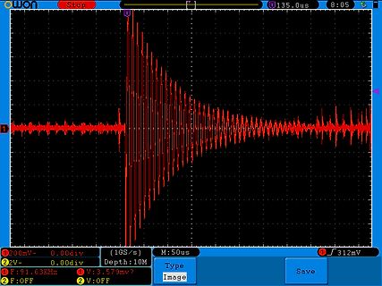
Stop 135.0us 8:05 1 200mV- 0.00div (1GS/s M:50us 312mV 2 2V- 0.00div Depth:10M F:91.63KHz V:3.579mv? F:OFF 2 V:OFF
-
Thread
[V] Robotron Netzteile aus K1520/K1520
habe ich noch einen Schwung Netzteile aus meiner K1510/K1520-Zeit gefunden. Im einzelnen sind das: 1x STM 9V/2,2A 1x STM 24V/5A 1x STM 5V/3,3A 2x STM 5V/10A 1x STZ K0367 +/-12V, +/-15V 1x STM K0361.03 5V/10A In einem Einschub gibt es noch: 1x Netzsicherung 1x Netzfilter 1x STM 5V/3,3A 1x STM 24V/2A 1x STM 12V/4,2A 1x STM 9V/2,2A Da die Netzteile seit ihrer letzten Nutzung bestimmt 15 Jahre nur herumlagen, gibt es keinerlei Garantie oder Rücknahme. Am liebsten ist mir Abholung (01705), die Dinger
-
 Bild
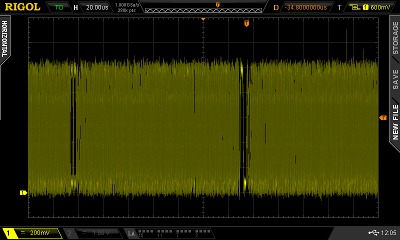
Oszilloskop-Screenshot eines Signals
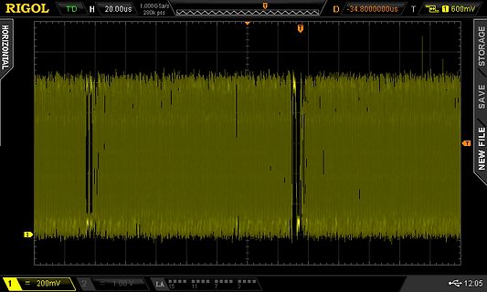
RIGOL T'D H 20.00us 1,000 GSa/s 280k pts D -34.800000us T 1 600mV 1 200mV 2 1.00 V LA 15 11 7 3 12:05
-
 Bild
Oszilloskop-Messkurve eines Signals
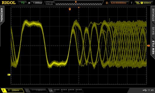
RIGOL 1.000us 1.000 GSa/s D 920.000000ns T 1 600mV 1 200mV 2 1.00V LA 15 11 7 3 11:45
-
Thread
Controller für Batteriebetrieb : Bootloader ?
Aufwärmzeit. Also wird es essentiell sein dass du den zwischendrin in den Idle Mode bringst. In Mode 1&4 braucht er scheinbar 46 mW! Nicht gerade pralle für Batterie Betrieb.
Stromverbrauch bei 3V runter. Hab ich ausprobiert und messtechnisch bestätigt. Mit einer CR2032 mit 230mAh typisch läuft das Teil Jahre. Solche modernen Controller haben etliche Möglichkeiten, um den Stromverbrauch runter zu bringen. https://www.microchip.com/en-us/product/PIC16F19176 So geht das.
-
 Bild
Oszilloskop-Screenshot eines SPI-Signals
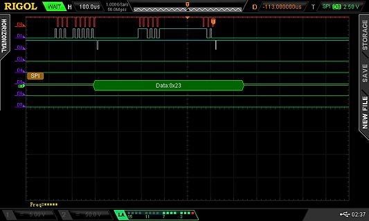
RIGOL WAIT H 100.0us 1.000 GSa/s 56.0M pts D/-113.000000us T SPI D0 2.50 V HORIZONTAL D0 D1 D2 D3 D4 D5 SPI D6 D7 Data:0x23 5.00 V 50.0 V LA 15 11 7 3 02:37
-
Thread
1,2V > 4-5V boost converter IC
Ich hab nochmal nachgemessen und benötige doch nur 50mA an 4V. Was würdet ihr empfehlen? Hab noch TPS61071 gefunden. Der BL8530 zieht an 1,3V leider 300mA.
Beitrag #7797616: > Ich kann’s immer noch nicht glauben, dass der MCP1640 überhaupt von > 5V/100mA aus 1,2V erzeugen kann ... Wer in das Datenblatt schaut, wird es abschätzen können. Dort steht: IOUT > 100 mA @ 1.2V VIN, 3.3V VOUT D.h. für 5V müsste dort stehen: IOUT > 60 mA @ 1.2V VIN,
-
 Bild
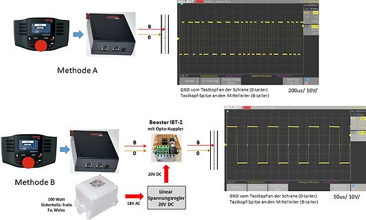
Vergleich zweier Messmethoden mit Oszilloskop-Ausschnitten
A B O GND vom Tastkopf an der Schiene (0-Leiter) Tastkopf-Spitze an den Mittelleiter (B-Leiter) 200us/ 10V/ SIGLENT M 200us/ Delay 1.36ms Methode B Booster IBT-2 mit Opto-Koppler 20V DC 18 AC 100 Watt Sicherheits-Trafo Fa. Weiss Linear Spannungsregler 20V DC GND vom Tastkopf an der Schiene (0-Leiter) Tastkopf-Spitze an den Mittelleiter (B-Leiter) 50us/ 10V/ SIGLENT M 50us/ Delay 660ns