-
PDF
LIS302DL.pdf
. . . . . . . . . . . . . . . . . . . . . . . . . . . . . . . . . . . . . . . . . 19 Table 11. Transfer when master is writing one byte to slave . . . . . . . . . . . . . . . . . . . . . . . . . . . . . . . 19 Table 12. Transfer when master is writing multiple bytes to slave . . . . . . . . . . . .
in „Verwirrung mit LIS302“ · Mikrocontroller und Digitale Elektronik ·
-
PDF
NAT7210_AN110.pdf
rights reserved. January 1998 FIFOs are simpler to interface to the NAT9914, but still increase GPIB transfer speed significantly. Using external FIFOs, the NAT9914 can transfer more than 1 Mbytes/s. Both a FIFO and a DMA controller, working together with a NAT9914, transfer data even faster. However, for
in „avr und gpib“ · Mikrocontroller und Digitale Elektronik ·
-
 Bild
Bild
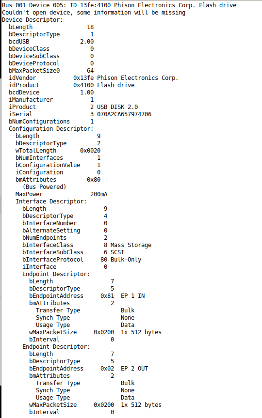
USB-Geräte-Deskriptor eines Flash-Laufwerks
Endpoint Descriptor: bLength 7 bDescriptorType 5 bEndpointAddress 0x81 EP 1 IN bmAttributes 2 Transfer Type Bulk Sync Type None Usage Type Data wMaxPacketSize 0x0200 1x 512 bytes bInterval 0 Endpoint Descriptor: bLength 7 bDescriptorType 5 bEndpointAddress 0x02 EP 2 OUT bmAttributes 2 Transfer
in „Linux - Infos über USB-Stick auslesen“ · PC Hard- und Software · · Screenshots
-
 Bild
Bild
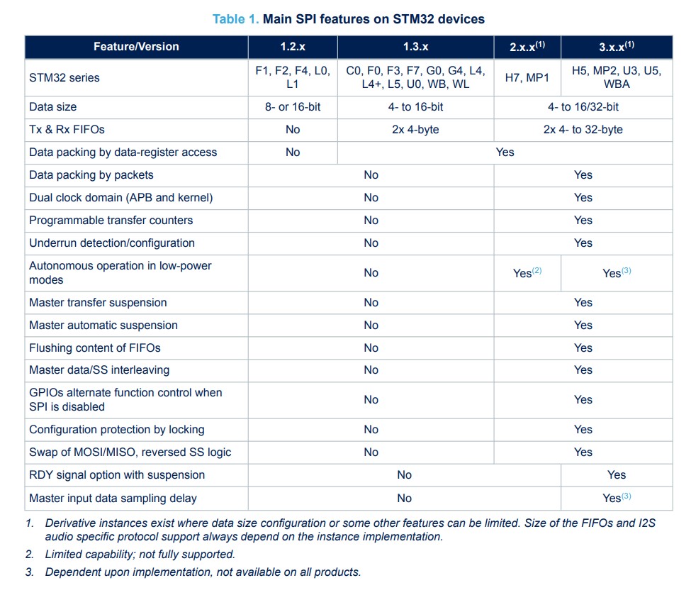
Vergleichstabelle der SPI-Features auf STM32-Geräten
Yes Yes Data packing by packets No Yes Yes Dual clock domain (APB and kernel) No Yes Programmable transfer counters No Yes Underrun detection/configuration No Yes Autonomous operation in low-power modes No Yes(2) Yes(3) Master transfer suspension No Yes Master automatic suspension No Yes Flushing content
in „Multichannel DAC mit SPi-DMA beschreiben“ · Mikrocontroller und Digitale Elektronik · · Screenshots
-
Datei
Code.txt
digitalWrite(CS, LOW); NOP; // delay 62.5ns on a 16MHz AtMega, 100ns erforderlich NOP; byte MSB = SPI.transfer(0); // höherwertiges Byte einlesen, D15 ... D8 byte LSB = SPI.transfer(0); // niederwertiges Byte einlesen, D7 ... D0 digitalWrite(CS, HIGH); KTemp = MSB << 8; KTemp = KTemp | LSB; KTemp = KTemp >
in „S-Function für mehrere Temperaturfühler“ · Mikrocontroller und Digitale Elektronik ·
-
Datei
max7219.h
sendAllCmdData(uint8_t cmd, uint8_t data); void sendCmdData(uint8_t cmd, uint8_t data); void startTransfer(void); void stopTransfer(void); void clear(void); private: void send1Byte(uint8_t data); }; extern class max7219 display; static const uint8_t MAX_DISPLAY_CHIPS = 4; static const uint8_t cmdNoOp =
in „Probleme bei der Ansteuerung MAX7219 mit 8x8 Dot Matrix“ · Mikrocontroller und Digitale Elektronik ·
-
PDF
IS2100EV1.61.pdf
D 12D11 D 10 D9 D8 D7 D6 D5 D4 D3 D2 D1 D0 2nd transfer Transfer order 2 8-bit data Data bus D17 D 16 D15 D 14 D13 D 12 D11 D 10 D9 D8 D7 D6 D5 D4 D3 D2 D1 D0 Input pin D17 D16 D15 D14 D13 D12 D11 D10 D9 D8 D7 D6 D5 D4 D3 D2 D1 D0 Register D15 D 14 D13
in „LCD-Modul OPTREX 351570AG“ · Mikrocontroller und Digitale Elektronik ·
-
PDF
ST_7262.pdf
(single-ended zero) state 1: USB lines are in SE0 (single-ended zero) state Bit 5 = CTR Correct Transfer. This bit is set by hardware when a correct transfer operation is per- Bit 1 = RXD Received data formed. The type of transfer can be determined by 0: No K-state 1: USB lines are in K-state looking
in „Unteschiede I²C / SPI“ · Mikrocontroller und Digitale Elektronik ·
-
Datei
lsusboutput.txt
TINY Endpoint Descriptor: bLength 7 bDescriptorType 5 bEndpointAddress 0x81 EP 1 IN bmAttributes 2 Transfer Type Bulk Synch Type None Usage Type Data wMaxPacketSize 0x0040 1x 64 bytes bInterval 0 Endpoint Descriptor: bLength 7 bDescriptorType 5 bEndpointAddress 0x01 EP 1 OUT bmAttributes 2 Transfer Type
in „MSP430 programmieren/debuggen unter Linux“ · Mikrocontroller und Digitale Elektronik ·
-
Datei
rrrr.asm
CompareB rjmp TIMER1_OVF ; Timer1 Overflow rjmp TIMER0_OVF ; Timer0 Overflow rjmp SPI_STC ; Serial Transfer Complete rjmp USART_RXC ; USART, Rx Complete rjmp USART_UDRE ; USART Data Register Empty rjmp USART_TXC ; USART, Tx Complete rjmp ANA_COMP ; Analog Comparator rjmp EXT_INT2 ; IRQ2 Request rjmp TIMER0
in „LCD wird immer aktualisiert“ · Mikrocontroller und Digitale Elektronik ·
-
Datei
debounce_fsm_orig_unsigned.vhd
; if counting = '1' then countval <= countval + 1; end if; end if; end if; end process counter; transfer_function : process (clk, rst) begin if rst = '0' then current_state <= IDLE; elsif rising_edge(clk) then case current_state is when IDLE => if taster = '0' then current_state <= WAITING; else current_state
in „State Machine erkennt Quartus nicht“ · FPGA, VHDL & Co. ·
-
Datei
sketch_feb24d.ino
= 0; digitalWrite(chipSelectPinADC, LOW); //Tell the MCP3201 to start sending data result = SPI.transfer(0x00); //Read in the first 8 bits of data result = result << 8; //Shift the data left so there is room for the next 8 bits inByte = SPI.transfer(0x00); //Read in the last 8 data bits from the MCP3201
in „MCP3201 ADC Probleme“ · Mikrocontroller und Digitale Elektronik ·
-
Datei
spi.c
// spi mode to use when transmitting .stay_act = 0, // sets this chip to stay active after last transfer .trans_delay = 0 // delay between each transfer }; spi_initMaster(&spi_tmp, &spi_options); // init function spi_set_master_mode(&spi_tmp); // set master mode spi_selectChip(&spi_tmp, 0); // select
in „SPI auf dem AT32UC3C-ek“ · Mikrocontroller und Digitale Elektronik ·
-
Datei
LC7980.h
LCD_DISPLAY_ON 32 #define LCD_DISPLAY_OFF 0 #define LCD_BLINK_16 64 #define LCD_BLINK_32 0 #define LCD_TRANSFER_EO 128 #define LCD_TRANSFER_BIT 0 #define LCD_BLINK_ON 8 #define LCD_BLINK_OFF 0 #define LCD_CURSOR_ON 4 #define LCD_CURSOR_OFF 0 #define LCD_MODE_GRAPHIC 2 #define LCD_MODE_TEXT 0 #define LCD_CG_EXT
in „Pollin DG016Z LCD-Display“ · Mikrocontroller und Digitale Elektronik ·
-
Datei
spi-test2.c
SPI-Funktionsprototypen **** int SPI_Init(void); int SPI_Send_Byte(unsigned char BYTE); int SPI_Transfer_Byte(unsigned char BYTE); // **** HAUPTPROGRAMM **** int main(void) { sei(); SPI_Init(); SPI_Send_Byte(0x55); for (;;) { } cli(); return (0); } // **** Funktionen **** int SPI_Init(void) // Das SPI-Interface
in „SPI gibt lediglich 4 Bits aus!“ · Mikrocontroller und Digitale Elektronik ·
-
Datei
Auslesen.ino
digitalWrite(CS, LOW); NOP; // delay 62.5ns on a 16MHz AtMega, 100ns erforderlich NOP; byte MSB = SPI.transfer(0); // höherwertiges Byte einlesen, D15 ... D8 byte LSB = SPI.transfer(0); // niederwertiges Byte einlesen, D7 ... D0 digitalWrite(CS, HIGH); KTemp = MSB << 8; KTemp = KTemp | LSB; KTemp = KTemp >
in „S-Function für mehrere Temperaturfühler“ · Mikrocontroller und Digitale Elektronik ·
-
Datei
sketch_feb24d.ino
++){ digitalWrite(chipSelectPinADC, LOW); //Tell the MCP3201 to start sending data result = SPI.transfer(0x00); //Read in the first 8 bits of data result = result << 8; //Shift the data left so there is room for the next 8 bits inByte = SPI.transfer(0x00); //Read in the last 8 data bits from the MCP3201
in „MCP3201 ADC Probleme“ · Mikrocontroller und Digitale Elektronik ·
-
PDF
HD44780.pdf
write. DB4 to DB7 4 I/O MPU Four high order bidirectional tristate data bus pins. Used for data transfer and receive between the MPU and the HD44780U. DB7 can be used as a busy flag. DB0 to DB3 4 I/O MPU Four low order bidirectional tristate data bus pins. Used for data transfer and receive between the
in „LCD Dotmatrix kaputt“ · Mikrocontroller und Digitale Elektronik ·
-
PDF
www.eio.com-hd44780_18-48-46.pdf
write. DB4 to DB7 4 I/O MPU Four high order bidirectional tristate data bus pins. Used for data transfer and receive between the MPU and the HD44780U. DB7 can be used as a busy flag. DB0 to DB3 4 I/O MPU Four low order bidirectional tristate data bus pins. Used for data transfer and receive between the
in „Fehler bei 4Bit LCD Init?“ · Mikrocontroller und Digitale Elektronik ·
-
PDF
HD44780__Dot_Matrix_LCD_Controller_Driver_.pdf
write. DB4 to DB7 4 I/O MPU Four high order bidirectional tristate data bus pins. Used for data transfer and receive between the MPU and the HD44780U. DB7 can be used as a busy flag. DB0 to DB3 4 I/O MPU Four low order bidirectional tristate data bus pins. Used for data transfer and receive between the
in „Falsche Zeichen bei LCD-Ausgabe“ · Mikrocontroller und Digitale Elektronik ·
-
PDF
hd44780u.pdf
write. DB4 to DB7 4 I/O MPU Four high order bidirectional tristate data bus pins. Used for data transfer and receive between the MPU and the HD44780U. DB7 can be used as a busy flag. DB0 to DB3 4 I/O MPU Four low order bidirectional tristate data bus pins. Used for data transfer and receive between the
in „Falsche Zeichen bei LCD-Ausgabe“ · Mikrocontroller und Digitale Elektronik ·
-
PDF
HD44780.PDF
write. DB4 to DB7 4 I/O MPU Four high order bidirectional tristate data bus pins. Used for data transfer and receive between the MPU and the HD44780U. DB7 can be used as a busy flag. DB0 to DB3 4 I/O MPU Four low order bidirectional tristate data bus pins. Used for data transfer and receive between the
in „Busy-Flag bei LCDs“ · Mikrocontroller und Digitale Elektronik ·
-
PDF
hd44780u.pdf
write. DB4 to DB7 4 I/O MPU Four high order bidirectional tristate data bus pins. Used for data transfer and receive between the MPU and the HD44780U. DB7 can be used as a busy flag. DB0 to DB3 4 I/O MPU Four low order bidirectional tristate data bus pins. Used for data transfer and receive between the
in „2. Zeile LCD“ · Mikrocontroller und Digitale Elektronik ·
-
PDF
hd44780.pdf
write. DB4 to DB7 4 I/O MPU Four high order bidirectional tristate data bus pins. Used for data transfer and receive between the MPU and the HD44780U. DB7 can be used as a busy flag. DB0 to DB3 4 I/O MPU Four low order bidirectional tristate data bus pins. Used for data transfer and receive between the
in „LCD ohne Umlaute?“ · Mikrocontroller und Digitale Elektronik ·
-
PDF
HD44780U.pdf
write. DB4 to DB7 4 I/O MPU Four high order bidirectional tristate data bus pins. Used for data transfer and receive between the MPU and the HD44780U. DB7 can be used as a busy flag. DB0 to DB3 4 I/O MPU Four low order bidirectional tristate data bus pins. Used for data transfer and receive between the
in „LCD ohne Datenblatt oder Hinweise zur Pinbelegung“ · Mikrocontroller und Digitale Elektronik ·
-
PDF
hd44780.pdf
write. DB4 to DB7 4 I/O MPU Four high order bidirectional tristate data bus pins. Used for data transfer and receive between the MPU and the HD44780U. DB7 can be used as a busy flag. DB0 to DB3 4 I/O MPU Four low order bidirectional tristate data bus pins. Used for data transfer and receive between the
in „LCD (von Tel) -Problem“ · Mikrocontroller und Digitale Elektronik ·
-
PDF
hd44780.pdf
write. DB4 to DB7 4 I/O MPU Four high order bidirectional tristate data bus pins. Used for data transfer and receive between the MPU and the HD44780U. DB7 can be used as a busy flag. DB0 to DB3 4 I/O MPU Four low order bidirectional tristate data bus pins. Used for data transfer and receive between the
in „HD44780 Zeichen im ROM“ · Mikrocontroller und Digitale Elektronik ·
-
PDF
hd44780.pdf
write. DB4 to DB7 4 I/O MPU Four high order bidirectional tristate data bus pins. Used for data transfer and receive between the MPU and the HD44780U. DB7 can be used as a busy flag. DB0 to DB3 4 I/O MPU Four low order bidirectional tristate data bus pins. Used for data transfer and receive between the
in „Sinnlose Probleme mit LCD...“ · Mikrocontroller und Digitale Elektronik ·
-
PDF
HD44780U.pdf
write. DB4 to DB7 4 I/O MPU Four high order bidirectional tristate data bus pins. Used for data transfer and receive between the MPU and the HD44780U. DB7 can be used as a busy flag. DB0 to DB3 4 I/O MPU Four low order bidirectional tristate data bus pins. Used for data transfer and receive between the
in „444780 LCD 5x10 klappt nicht richtig!“ · Mikrocontroller und Digitale Elektronik ·
-
PDF
hd44780.pdf
write. DB4 to DB7 4 I/O MPU Four high order bidirectional tristate data bus pins. Used for data transfer and receive between the MPU and the HD44780U. DB7 can be used as a busy flag. DB0 to DB3 4 I/O MPU Four low order bidirectional tristate data bus pins. Used for data transfer and receive between the
in „System(Mikrocontroller usw) mit Batterie betreiben“ · Mikrocontroller und Digitale Elektronik ·
-
PDF
hd44780.pdf
write. DB4 to DB7 4 I/O MPU Four high order bidirectional tristate data bus pins. Used for data transfer and receive between the MPU and the HD44780U. DB7 can be used as a busy flag. DB0 to DB3 4 I/O MPU Four low order bidirectional tristate data bus pins. Used for data transfer and receive between the
in „ATMEL_2x16LCD_Zeile 2“ · Mikrocontroller und Digitale Elektronik ·
-
PDF
HD44780.pdf
write. DB4 to DB7 4 I/O MPU Four high order bidirectional tristate data bus pins. Used for data transfer and receive between the MPU and the HD44780U. DB7 can be used as a busy flag. DB0 to DB3 4 I/O MPU Four low order bidirectional tristate data bus pins. Used for data transfer and receive between the
in „LCD Ansteuerung (PIC 18F1220)“ · Mikrocontroller und Digitale Elektronik ·
-
PDF
HD44780.PDF
write. DB4 to DB7 4 I/O MPU Four high order bidirectional tristate data bus pins. Used for data transfer and receive between the MPU and the HD44780U. DB7 can be used as a busy flag. DB0 to DB3 4 I/O MPU Four low order bidirectional tristate data bus pins. Used for data transfer and receive between the
in „LCD Display in 4 Bit Modus bringen“ · Mikrocontroller und Digitale Elektronik ·
-
PDF
HD44780.PDF
write. DB4 to DB7 4 I/O MPU Four high order bidirectional tristate data bus pins. Used for data transfer and receive between the MPU and the HD44780U. DB7 can be used as a busy flag. DB0 to DB3 4 I/O MPU Four low order bidirectional tristate data bus pins. Used for data transfer and receive between the
in „Datenblatt zu HD44780 1602 LCD Modul Display Anzeigen 2X16 Zeichen“ · Mikrocontroller und Digitale Elektronik ·
-
PDF
HD44780.pdf
write. DB4 to DB7 4 I/O MPU Four high order bidirectional tristate data bus pins. Used for data transfer and receive between the MPU and the HD44780U. DB7 can be used as a busy flag. DB0 to DB3 4 I/O MPU Four low order bidirectional tristate data bus pins. Used for data transfer and receive between the
in „Standart LCD per i2c expander betreiben“ · Mikrocontroller und Digitale Elektronik ·
-
PDF
hd44780u_Datenblatt.pdf
write. DB4 to DB7 4 I/O MPU Four high order bidirectional tristate data bus pins. Used for data transfer and receive between the MPU and the HD44780U. DB7 can be used as a busy flag. DB0 to DB3 4 I/O MPU Four low order bidirectional tristate data bus pins. Used for data transfer and receive between the
in „hd44780 / LCD SC1602D / ATmega16 (STK500)“ · Mikrocontroller und Digitale Elektronik ·
-
PDF
HD44780.pdf
write. DB4 to DB7 4 I/O MPU Four high order bidirectional tristate data bus pins. Used for data transfer and receive between the MPU and the HD44780U. DB7 can be used as a busy flag. DB0 to DB3 4 I/O MPU Four low order bidirectional tristate data bus pins. Used for data transfer and receive between the
in „Ist der HD44780 nun 8 oder 16 Zeichen lang?“ · Mikrocontroller und Digitale Elektronik ·
-
PDF
HD44780U.pdf
write. DB4 to DB7 4 I/O MPU Four high order bidirectional tristate data bus pins. Used for data transfer and receive between the MPU and the HD44780U. DB7 can be used as a busy flag. DB0 to DB3 4 I/O MPU Four low order bidirectional tristate data bus pins. Used for data transfer and receive between the
in „LCD Initialisierung Mikrocontroller“ · Mikrocontroller und Digitale Elektronik ·
-
PDF
Explanation_of_Data_Sheet_Parameters__INF.pdf
Safe Operating Area . . . . . . . . . 28 4.4 TypischeÜbertragungscharakteristik 29 4.4 Typical Transfer Characteristic . 29 Explanation 4 V1.0, 2002-04 Erläuterung der Datenblattwerte Explanation of Data Sheet Parameters Inhalt Seite Contents Page 4.5 Typischer Drain-Source 4.5 Typical Drain-Source
in „Sperrstrom BJT vs. MOSFET“ · Analoge Elektronik und Schaltungstechnik ·
-
Datei
avrasm.txt
branch if same or higher (C = 0) nach Vergleich von Zahlen ohne Vorzeichen brtc label ; branch if transfer flag cleared (T = 0) brts label ; branch if transfer flag set (T = 1) brvc label ; branch if overflow flag cleared (V = 0) brvs label ; branch if overflow flag set (V = 1) bset 7 ; bit set in SREG register bst r0, 7 ; bit store in transfer flag (T flag bekommt Wert von Bit) cbi io31, 7 ; clear bit in IO-Register (nur untere 32 IO-Adressen) cbr r16, 255 ; clear bits in register (r16 AND 1-er Komplement von Konstante, Ergebnis in r16)
-
PDF
avrasm.pdf
nach Vergleich von Zahlen ohne Vorzeichen grammablauf rückwärts gesprungen. brtc label ; branch if transfer flag cleared (T = 0) brts label ; branch if transfer flag set (T = 1) rjmp loop brvc label ; branch if overflow flag cleared (V = 0) brvs label ; branch if overflow flag set (V = 1) bset 7 ; bit set in SREG register Hex cffd ist binär bst r0, 7 ; bit store in transfer flag (T flag bekommt Wert von Bit) cbi io31, 7 ; clear bit in IO-Register (nur untere 32 IO-Adressen) 1100 1111 1111 1101 cbr r16, 255 ; clear bits in register (r16 AND 1-er Komplement von Konstante
-
Datei
reni_v0.67.c
//// , FUNCTION_WAIT // wait 1000 msec , FUNCTION_LOAD_PIPE // reset pipe 0x82, scheduling data transfer , FUNCTION_START_MEASURE , FUNCTION_STOP_MEASURE , END_PROGRAM }; // Seen original order of commands: // DOWN_Zerosta, d3 // DOWN_Zerodyn, cc // DOWN_Unkn3, cf // DOWN_Conf8060, % // DOWN_Unkn5, d800
in „Schreiben eines USB-Treibers mit libusb-win32“ · Softwareentwicklung ·
-
PDF
AIP31068L.pdf
9-bit) uses three pins(CSB、SDA、SCK) to enter commands and data. Timing sequence is shown below. Transfer command mode: Transfer data mode: Note: 1、the RS bit defines whether the following data bytes are interpreted as COMMAND or as DATA: When RS is “low”, the following data is COMMAND. When RS is “high
in „ESP32 Treiber für I2C Display AiP31068L ardiuno.h wire.h“ · Mikrocontroller und Digitale Elektronik ·
-
Datei
ds18s20.h
out] pDS18x20 pointer to the structure that represent DS18S20 * @return uint8_t 1 for valid data transfer, 0 for CRC error detected. */ uint8_t DS18x20_ReadROM(TSDS18x20 *pDS18x20); /** * @brief This functions initiates a temperature conversion via CONVERT_T function command * and then issues READ_SCRATCHPAD
in „Timerberechnung die hunderste“ · Mikrocontroller und Digitale Elektronik ·
-
Datei
16F1827_CSM_00.ASM
2Wire Interface LcdBit ;Bitcounter LcdFlags ;flow control data/instructions ; cntOscillations ;transfer TMR0 to LCD cntTime ;counter software timebase ; BCD2, BCD1,BCD0 ;BCD to decimal hundred, ten, ones ACb3,ACb2,ACb1,ACb0 ;variables to calculate cntBit,cntDig ;helper counter DDRAM_Adr ;DDRAM-address
in „PIC16F1827 Capacitive Sensing Module Assembler“ · Mikrocontroller und Digitale Elektronik ·
-
PDF
SFS0405T4.pdf
Characteristics Input Capacitance C iss V DS0V - 560 - Output Capacitance Coss VGS0V - 40.6 - pF Reverse Transfer Capacitance C rss f=1.0MHZ - 30.9 - Switching Characteristics Turn-on Delay Time d(on) - 10.5 - V DD0V, V =1GS Turn-on Rise Time tr R =3.3, I =3A - 9.3 - ns Turn-off Delay Time t G D - 35.7 - d(off
in „Bezugsquelle oder Alternative gesucht.“ · Mikrocontroller und Digitale Elektronik ·
-
PDF
SPI_74HC595.pdf
used as a latch clock. It can be set up as either a slave-select or a general purpose output to transfer SR contents to the output latch after the data is shifted in. This is a positive edge triggered device. It requires: CPOL=CPHA=1. +5V 74HC595 10 RST QA15 QB 1 MOSI 14 SerIn QC 2 11 ShClk QD 3 Outputs
in „SPI + 74HC595“ · Mikrocontroller und Digitale Elektronik ·
-
PDF
SPI_74HC595.pdf
used as a latch clock. It can be set up as either a slave-select or a general purpose output to transfer SR contents to the output latch after the data is shifted in. This is a positive edge triggered device. It requires: CPOL=CPHA=1. +5V 74HC595 10 RST QA15 QB 1 MOSI 14 SerIn QC 2 11 ShClk QD 3 Outputs
in „Porterweiterug und I2C bus“ · Mikrocontroller und Digitale Elektronik ·
-
Datei
main.c
while(1) { } return 1; } uint16_t EVAL_AUDIO_GetSampleCallBack(void) { return 1; } void EVAL_AUDIO_TransferComplete_CallBack(uint32_t pBuffer, uint32_t Size) { //retVal_Play = EVAL_AUDIO_Play((uint16_t*)(AUDIO_SAMPLE + 58), 990000 - 58); retVal_Play = EVAL_AUDIO_Play((uint16_t*) auiBuffer, SOUNDBUFFER * 4); } void EVAL_AUDIO_HalfTransfer_CallBack(uint32_t pBuffer, uint32_t Size) { } void EVAL_AUDIO_Error_CallBack(void* pData) { while(1); } uint32_t Codec_TIMEOUT_UserCallback(void) { while(1); return 1; }
in „STM32F4 Discovery Audio DAC CS43L22“ · Mikrocontroller und Digitale Elektronik ·
-
Datei
epdif.cpp
digitalRead(pin); } void EpdIf::DelayMs(unsigned int delaytime) { delay(delaytime); } void EpdIf::SpiTransfer(unsigned char data) { digitalWrite(CS_PIN, LOW); SPI.transfer(data); digitalWrite(CS_PIN, HIGH); } int EpdIf::IfInit(void) { pinMode(CS_PIN, OUTPUT); pinMode(RST_PIN, OUTPUT); pinMode(DC_PIN, OUTPUT
in „ESP8266 mit Waveshare 7,5" E-Paper - funktioniert nicht“ · Mikrocontroller und Digitale Elektronik ·