-
Datei
main.c
/* * main.c * * Created on: 14.04.2013 * Author: Oki */ // // Anpassungen im makefile: // ATMega8 => MCU=atmega8 im makefile einstellen // lcd-routines.c in SRC = ... Zeile anh ngen // #include <avr/io.h> #include "lcd-routines.h" int main(void) { // Initialisierung des LCD // Nach der Initialisierung
in „LCD-Display 204B - brauche Hilfe“ · Mikrocontroller und Digitale Elektronik ·
-
Datei
main.c
/************************************************************** Es soll alle 8,4 Sekunden im Wechsel 0 bzw. 1 gesendet werden. Am korrespondierenden Slave soll zur Indikation jeweils die LEDs an bzw. aus gehen. Verdrahtung: ATMega16 --> ATMega328P MISO(Master) PB6 [Eingang ] --
in „SPI-Kommunikation ATMEGA16 - ATMEGA328P“ · Mikrocontroller und Digitale Elektronik ·
-
Datei
LCDTest.c
// // Anpassungen im makefile: // ATMega8 => MCU=atmega8 im makefile einstellen // lcd-routines.c in SRC = ... Zeile anhängen // #include <avr/io.h> #include "lcd-routines.h" int main(void) { // Initialisierung des LCD // Nach der Initialisierung
in „attiny2313, LCD, 4-Bit, C, Einzelne Zeichen falsch“ · Mikrocontroller und Digitale Elektronik ·
-
Datei
main.c
// // Anpassungen im makefile: // ATMega8 => MCU=atmega8 im makefile einstellen // lcd-routines.c in SRC = ... Zeile anhängen // #include <avr/io.h> #include "lcd-routines.h" int main(void) { // Initialisierung des LCD // Nach der Initialisierung
in „LCD, HD44780 und KS0076“ · Mikrocontroller und Digitale Elektronik ·
-
Datei
main.c
// // Anpassungen im makefile: // ATMega8 => MCU=atmega8 im makefile einstellen // lcd-routines.c in SRC = ... Zeile anhängen // #include <avr/io.h> #include "lcd-routines.h" int main(void) { // Initialisierung des LCD // Nach der Initialisierung
in „Probleme mit HD44780 1602 LCD Module“ · Mikrocontroller und Digitale Elektronik ·
-
Datei
GccApplication1.c
// // Anpassungen im makefile: // ATMega8 => MCU=atmega8 im makefile einstellen // lcd-routines.c in SRC = ... Zeile anhängen // #include <avr/io.h> #include "lcd-routines.h" #include "lcd-routines.c" int main(void) { // Initialisierung des
in „LCD ansteuern funktioniert nicht“ · Mikrocontroller und Digitale Elektronik ·
-
Datei
main.c
// // Anpassungen im makefile: // ATMega8 => MCU=atmega8 im makefile einstellen // lcd-routines.c in SRC = ... Zeile anhängen // #include <avr/io.h> #include <stdint.h> #include "lcd-routines.h" int main(void) { // Initialisierung des LCD
in „lcd initialisiert nur ein mal (ATmega8)“ · Mikrocontroller und Digitale Elektronik ·
-
Datei
LCD_STK500.c
// // Anpassungen im makefile: // ATMega8 => MCU=atmega8 im makefile einstellen // lcd-routines.c in SRC = ... Zeile anhängen // #include <avr/io.h> #include "lcd-routines.h" int main(void) { // Initialisierung des LCD // Nach der Initialisierung
in „Probleme mit EA W62B-N3LW LCD an STK 500“ · Mikrocontroller und Digitale Elektronik ·
-
Datei
main.c
// // Anpassungen im makefile: // ATMega8 => MCU=atmega8 im makefile einstellen // lcd-routines.c in SRC = ... Zeile anhängen // #include <avr/io.h> #include "lcd-routines.h" int main(void) { // Initialisierung des LCD // Nach der Initialisierung
in „EA DOG 3,3V 4bit (AVR-GCC-Tutorial/LCD-Ansteuerung)“ · Mikrocontroller und Digitale Elektronik ·
-
Datei
main.c
// // Anpassungen im makefile: // ATMega8 => MCU=atmega8 im makefile einstellen // lcd-routines.c in SRC = ... Zeile anhängen // #include <avr/io.h> #include "lcd-routines.h" int main(void) { // Initialisierung des LCD // Nach der Initialisierung
in „AVR-GCC-Tutorial/LCD-Ansteuerung "undefined referece to 'lcd_data'“ · Mikrocontroller und Digitale Elektronik ·
-
Datei
LED_s.txt
*********************** ;Beschreibung: ;Dieses Programm lässt eine LED am Pin0 des Ports B eines ATmega8 ;mit 2Hz blinken (Bei 4MHz Oszillator-Frequenz). ;Ein Timer (TC0) zählt nach oben bis zum Überlauf, woraufhin ;ein TC0-Überlauf-Interrupt erzeugt wird und zur "TIM0_OVF"-ISR verzweigt wird, ;die dann
in „ATmega8: LED blinken lassen“ · Mikrocontroller und Digitale Elektronik ·
-
Datei
SIR.c
(__AVR_ATtiny85__) // ATtiny45 / ATtiny85: #if F_CPU >= 16000000L OCR1C = (F_CPU / F_INTERRUPTS / 8) - 1; // compare value: 1/15000 of CPU frequency, presc = 8 TCCR1 = (1 << CTC1) | (1 << CS12); // switch CTC Mode on, set prescaler to 8 #else OCR1C = (F_CPU / F_INTERRUPTS / 4) - 1; // compare value
in „uart_puts funktioniert nur sporadisch (zusammen mit IRMP)“ · Mikrocontroller und Digitale Elektronik ·
-
Datei
usart.cpp
<<UART0_BIT_TXEN); /* Set frame format: asynchronous, 8data, no parity, 1stop bit */ #ifdef UART0_CONTROLC #ifdef UART0_BIT_URSEL UART0_CONTROLC = (1<<UART0_BIT_URSEL)|(1<<UART0_BIT_UCSZ1)|(1<<UART0_BIT_UCSZ0); #else UART0_CONTROLC = (1<<UART0_BIT_UCSZ1)|
in „ISR Code schneller machen?“ · Mikrocontroller und Digitale Elektronik ·
-
Datei
usart.cpp
<<UART0_BIT_TXEN); /* Set frame format: asynchronous, 8data, no parity, 1stop bit */ #ifdef UART0_CONTROLC #ifdef UART0_BIT_URSEL UART0_CONTROLC = (1<<UART0_BIT_URSEL)|(1<<UART0_BIT_UCSZ1)|(1<<UART0_BIT_UCSZ0); #else UART0_CONTROLC = (1<<UART0_BIT_UCSZ1)|
in „ISR Code schneller machen?“ · Mikrocontroller und Digitale Elektronik ·
-
Datei
lcd.c
#define DDR(x) (*(&x - 1)) /* address of data direction register of port x */ #if defined(__AVR_ATmega64__) || defined(__AVR_ATmega128__) /* on ATmega64/128 PINF is on port 0x00 and not 0x60 */ #define PIN(x) ( &PORTF==&(x) ? _SFR_IO8(0x00) : (*(&x - 2)) ) #else #define PIN(x) (*(&x - 2)) /* address
in „ATMega16 PORTA defekt?“ · Mikrocontroller und Digitale Elektronik ·
-
Datei
lcd.c
#define DDR(x) (*(&x - 1)) /* address of data direction register of port x */ #if defined(__AVR_ATmega64__) || defined(__AVR_ATmega128__) /* on ATmega64/128 PINF is on port 0x00 and not 0x60 */ #define PIN(x) ( &PORTF==&(x) ? _SFR_IO8(0x00) : (*(&x - 2)) ) #else #define PIN(x) (*(&x - 2)) /* address
in „Display Programmierung mit GCC 16x4 Display“ · Mikrocontroller und Digitale Elektronik ·
-
Datei
OLED_2_16.c
// // Anpassungen im makefile: // ATMega8 => MCU=atmega8 im makefile einstellen // lcd-routines.c in SRC = ... Zeile anhängen // #include <avr/io.h> #include "lcd.h" int main(void) { // Initialisierung des LCD // Nach der Initialisierung
in „OLED Display EA W162 init klappt nicht“ · Mikrocontroller und Digitale Elektronik ·
-
Datei
t6963c.h
with 6x8 font 30 with 8x8 font * Vout (19) Variable Resistor with GND and centre with VO ( Pin 4 ) * BLA (20) Back light + * BLK (21) Back light - * DSPON (22) I don't Know but i think means display ON or ...
-
Datei
Drehgeber_per_interrupt.c
char ergebnis_str[MAX_STELLEN+1]; // funktionen zur ser. Datenausgabe void init_serio0(void) { uint8_t temp; UCSR0B = 0x0; // alles abschalten UCSR0C = BIT(UCSZ01) | BIT(UCSZ00); // default wie nach reset 8 Bit, async, no par. UBRR0=((F_CPU/16L/(DEF_BAUDRATE/10L)+5L)/10L) - 1; // passend gerundet UCSR0B
in „Drehgeber per Interrupt auswerten, AVR“ · Projekte & Code ·
-
Datei
test.c
// // Anpassungen im makefile: // ATMega8 => MCU=atmega8 im makefile einstellen // lcd-routines.c in SRC = ... Zeile anhängen // #include <avr/io.h> #include "lcd-routines.h" int main(void) { // Initialisierung des LCD // Nach der Initialisierung
in „splc780d LCD Pollin“ · Mikrocontroller und Digitale Elektronik ·
-
Datei
Display-Ansteuern.c
Created: 18.10.2013 12:48:35 * Author: Test1 */ #include <avr/io.h> // // Anpassungen im makefile: // ATMega8 => MCU=atmega8 im makefile einstellen // lcd-routines.c in SRC = ... Zeile anhängen // #include <avr/io.h> #include "lcd-routines.h" int main(void) { // Initialisierung des LCD // Nach der Initialisierung
in „LCD zeigt nichts an“ · Mikrocontroller und Digitale Elektronik ·
-
Datei
LCD8.c
// // Anpassungen im makefile: // ATMega8 => MCU=atmega8 im makefile einstellen // lcd-routines.c in SRC = ... Zeile anhängen // //#include <iostream> #include <stdlib.h> #include <avr/io.h> //#include <lcd-routines.h> #include "lcd-routines.h
in „LCD funktioniert nich“ · Mikrocontroller und Digitale Elektronik ·
-
Datei
GccApplication20.c
GccApplication20.c * * Created: 14.05.2016 17:19:14 * Author: Tobi */ // // Anpassungen im makefile: // ATMega8 => MCU=atmega8 im makefile einstellen // lcd-routines.c in SRC = ... Zeile anhängen // #include <avr/io.h> #include "lcd-routines.h" int main(void) { // Initialisierung des LCD // Nach der Initialisierung
in „20x4 LCD an MyAVR Board anbinden“ · Mikrocontroller und Digitale Elektronik ·
-
Datei
main.c
((1<<PGERS) | (1<<SPMEN)) #define spm_pagewritecode ((1<<PGWRT) | (1<<SPMEN)) #if (defined(__AVR_ATmega8__)) // stolen from spminterface for ATmega8 const uint16_t bootloader__do_spm[15] PROGMEM = { 0x2dec, 0x2dfd, 0xb6b7, 0xfcb0, 0xcffd, 0xbf27, 0x95e8, 0xb6b7, 0xfcb0, 0xcffd, 0xe121, 0xb6b7, 0xfcb6
in „ATmega-Bootloader vom Hauptprogramm aus flashen“ · Mikrocontroller und Digitale Elektronik ·
-
PDF
Powermeter.pdf
below. Summary: Defaults Table 7. Firmware Defaults. Parameter Value Note Compiler IAR 3.10 Device ATmega88 8kB FLASH, 1024b RAM, 512b EEPROM Starting current 2mA See I_MIN constant Calculation cycle 200ms See system clock and NMAX constant Energy pulse rate 10000 imp/kWh See MC calibration coefficient
in „230V Leistung erfassen mit ATmega128“ · Mikrocontroller und Digitale Elektronik ·
-
PDF
volt230.pdf
below. Summary: Defaults Table 7. Firmware Defaults. Parameter Value Note Compiler IAR 3.10 Device ATmega88 8kB FLASH, 1024b RAM, 512b EEPROM Starting current 2mA See I_MIN constant Calculation cycle 200ms See system clock and NMAX constant Energy pulse rate 10000 imp/kWh See MC calibration coefficient
in „Netzteil ohne Trafo“ · Mikrocontroller und Digitale Elektronik ·
-
PDF
energymeter.pdf
below. Summary: Defaults Table 7. Firmware Defaults. Parameter Value Note Compiler IAR 3.10 Device ATmega88 8kB FLASH, 1024b RAM, 512b EEPROM Starting current 2mA See I_MIN constant Calculation cycle 200ms See system clock and NMAX constant Energy pulse rate 10000 imp/kWh See MC calibration coefficient
in „Leistungsmessung über Shunt?“ · Analoge Elektronik und Schaltungstechnik ·
-
PDF
doc2566.pdf
below. Summary: Defaults Table 7. Firmware Defaults. Parameter Value Note Compiler IAR 3.10 Device ATmega88 8kB FLASH, 1024b RAM, 512b EEPROM Starting current 2mA See I_MIN constant Calculation cycle 200ms See system clock and NMAX constant Energy pulse rate 10000 imp/kWh See MC calibration coefficient
in „Cadsoft Eagle“ · Platinen ·
-
Datei
iom644pa.h
iom644PA.h" #else # error "Attempt to include more than one <avr/ioXXX.h> file." #endif #ifndef _AVR_ATmega644PA_H_ #define _AVR_ATmega644PA_H_ 1 /* Registers and associated bit numbers. */ #define PINA _SFR_IO8(0x00) #define PINA0 0 #define PINA1 1 #define PINA2 2 #define PINA3 3 #define PINA4 4 #define
in „ATMega644p USART-Interruptvector?“ · Mikrocontroller und Digitale Elektronik ·
-
Datei
fuses.txt
# Fuses für ATmega32, Projekt: IBIS VDV300 Wandler # Low Fuse Byte: # Externer Quarz 8 MHz (Full Swing), Start-up time: 16K CK + 64 ms # BODEN (Brown-Out Detection Enable) # Default SUT/CKSEL für 8 MHz Quarz: 1111 1110
in „Codecontrolle und Fragen zu Microchip Studio“ · Mikrocontroller und Digitale Elektronik ·
-
PDF
ch32v003_getting_started.pdf
Ardudino UNO / nano oder eines AVR-Systems mit zugänglichen GPIO-Pins und einer USB2UART Bridge. ATmega328, ATmega168, ATmega8 und ATtiny2313 sind in der Lage, die Firmware in den Programmer zu flashen. Übersicht der Schritte zum Aufbau des Selbstbauprogrammers und „erste Schritte“ bei der Programmierung
in „CH32V003: Selbstbauprogrammer und "Getting started"“ · Projekte & Code ·
-
PDF
ch32v003_getting_started.pdf
Ardudino UNO / nano oder eines AVR-Systems mit zugänglichen GPIO-Pins und einer USB2UART Bridge. ATmega328, ATmega168, ATmega8 und ATtiny2313 sind in der Lage, die Firmware in den Programmer zu flashen. Übersicht der Schritte zum Aufbau des Selbstbauprogrammers und „erste Schritte“ bei der Programmierung
in „CH32V003: Selbstbauprogrammer und "Getting started"“ · Projekte & Code ·
-
Datei
main.c
// // Anpassungen im makefile: // ATMega8 => MCU=atmega8 im makefile einstellen // lcd-routines.c in SRC = ... Zeile anhängen // #include <avr/io.h> #include <stdlib.h> #include "lcd-routines.h" // Beispiel int variable = 42; int main(void
in „LCD - Datei einbinden (".")“ · Mikrocontroller und Digitale Elektronik ·
-
Datei
Display2909.c
// // Anpassungen im makefile: // ATMega8 => MCU=atmega8 im makefile einstellen // lcd-routines.c in SRC = ... Zeile anhängen // #include <avr/io.h> #include "lcd-routines.h" int main(void) { // Initialisierung des LCD // Nach der Initialisierung
in „Atmega16 EA DIP204-6 4-line“ · Mikrocontroller und Digitale Elektronik ·
-
Datei
lcd-test.c
// // Anpassungen im makefile: // ATMega8 => MCU=atmega8 im makefile einstellen // lcd-routines.c in SRC = ... Zeile anhängen // #define XTAL 8000000 #define F_CPU XTAL #include <avr/io.h> #include <util/delay.h> #include "lcd-routines.h"
in „LCD-Display an ATMega8 funktioniert nicht“ · Mikrocontroller und Digitale Elektronik ·
-
Datei
ASM_Source2.txt
--------------------------------------------------------------- ;| Title : myAVR Grundgerüst für ATmega8 ;+---------------------------------------------------------------------- ;| Funktion : ... ;| Schaltung : ... ;+---------------------------------------------------------------------- ;| Prozessor : ATmega8 ;| Takt : 3,6864 MHz ;| Sprache : Assembler ;| Datum : ... ;| Version : ... ;| Autor : ... ;+---------------------------------------------------------------------- ;.include "AVR.H" .include "m8def.inc
in „ADC-Input und Auswahlverfahren“ · Mikrocontroller und Digitale Elektronik ·
-
Datei
BalancingWii.ino
This is the balancing robot based on modified/extended MultiWii 2.3 firmware. Video: http://youtu.be/U8bBna9iWCU Blogs: - http://forum.rcdesign.ru/blogs/83206/blog18515.html - http://www.multiwii.com/forum/viewtopic.php?f=7&t=4787 Hardware: - Arduino nano (atmega328p) - mpu6050 gyro-accelerometer (GY_521
-
Datei
Header.inc
Headerdatei ;HHHHHHHHHHHHHHHHHHHHHHHHHHHHHHHHHHHHHHHHHHHHHHHHHHHHHHHHHHHHHHHHHHHHHHHHHHHHHHH ;Der ATmega88PA laeuft mit einem 1,8432 MHz Quarz und wird an 3,3V betrieben. ; ;FUSES Extendet $F9, High $97, Low $EA ;debugWIRE Enable, EEPROM beim Loeschen nicht mitloeschen, ;Sytemtakt nicht durch 8 teilen
in „AVR8ASM TWI Interrupt“ · Mikrocontroller und Digitale Elektronik ·
-
Datei
out_of_range_build_output.txt
avr-gcc -mmcu=atmega2560 -Wl,-section-start=.data=0x802200,--defsym=__heap_end=0x80ffff -v -Wl,--script=morepgmavr6.x -Wl,-Map=eclcpu.map [....] -L"C:\avrgcc\lib" -L"D:\riedl\eclcpu\trunk" -o eclcpu.elf Using built-in
in „.data-Segment größer als 8KB möglich“ · Mikrocontroller und Digitale Elektronik ·
-
Datei
Tastatur.asm
writtten by: Heiko Knejfl * ;date: 20.03.2006 * ;version: V1.0 * ;file saved as: Tastatur * ;for AVR: Atmega16 * ;clock frequency: 8Mhz * ;*********************************************** ;Program function:___Tastatur-Emulation________________________________________________________ ;____________________________________________________________________________ .device ATmega16 .nolist .include "m16def.inc" ; Definitionsdatei für ATmega16 ;****************************************************************************** ; Parameter definieren ;*****************************
in „Tastatur-Emulator gesucht“ · Mikrocontroller und Digitale Elektronik ·
-
Datei
i2c.c
set pull-up resistors on I2C bus pins // TODO: should #ifdef these sbi(PORTC, 0); // i2c SCL on ATmega163,323,16,32,etc sbi(PORTC, 1); // i2c SDA on ATmega163,323,16,32,etc //sbi(PORTD, 0); // i2c SCL on ATmega128,64 //sbi(PORTD, 1); // i2c SDA on ATmega128,64 // clear SlaveReceive and SlaveTransmit
in „TWI, I2C Master-Slave mit AVR“ · Mikrocontroller und Digitale Elektronik ·
-
PDF
displayinterface_arduino.pdf
stxlcd.print("Hallo"); stxlcd.gotoxy(3,2); Grundsätzlich kön stxlcd.print("Welt"); senduserchar(uint8_t nr, const uint8_t *userch) sendet das Bitmap eines Userzeichen bestehend aus 8 Bytes an das Displayinterface Übergabe: nr : Ascii-Codenummer, unter der das gesendete Bitmap als Zeichen abrufbar ist *userch: Zeiger auf ein 8 Byte großes Array, das das Bitmap des Userzeichens enthält. Beispiel (gibt das Eurozeichen an Position 1 in Zeile 2 aus): // Bitmap des Eurozeichens const uint8_t userchar[8] = { 0x07, 0x08, 0x1e, 0x08
in „Arduino: serielles Ansprechen eines HD44780 Displays über SoftSerial“ · Projekte & Code ·
-
Datei
sht75_funzlcd.c
LCD_Display.c * * Created: 04.12.2012 07:25:42 * Author: Tom */ // // Anpassungen im makefile: // ATMega8 => MCU=atmega8 im makefile einstellen // lcd-routines.c in SRC = ... Zeile anhängen // #include <avr/io.h> #include "lcd-routines.h" #include "sht71.h" #include <stdlib.h> int main(void) { // Initialisierung
in „SHT75 mit Atmega32 am stk500“ · Mikrocontroller und Digitale Elektronik ·
-
Datei
iom328p.h
1 #define PCIF2 2 #define EIFR _SFR_IO8(0x1C) #define INTF0 0 #define INTF1 1 #define EIMSK _SFR_IO8(0x1D) #define INT0 0 #define INT1 1 #define GPIOR0 _SFR_IO8(0x1E) #define GPIOR00 0 #define GPIOR01 1 #define GPIOR02 2 #define GPIOR03 3
in „ATMega16 mehrere Taster an INT0“ · Mikrocontroller und Digitale Elektronik ·
-
Datei
i2c.c
pull-up resistors on I2C bus pins ///@todo : should #ifdef these //sbi(PORTC, 0); // i2c SCL on ATmega163,323,16,32,etc //sbi(PORTC, 1); // i2c SDA on ATmega163,323,16,32,etc sbi(PORTD, 0); // i2c SCL on ATmega128,64 sbi(PORTD, 1); // i2c SDA on ATmega128,64 // clear SlaveReceive and SlaveTransmit handler
in „TWI, I2C Master-Slave mit AVR“ · Mikrocontroller und Digitale Elektronik ·
-
Datei
MCP_Reg.h
**************************************/ #define RXF0SIDH 0x00 #define RXF0SIDL 0x01 #define RXF0EID8 0x02 #define RXF0EID0 0x03 #define RXF1SIDH 0x04 #define RXF1SIDL 0x05 #define RXF1EID8 0x06 #define RXF1EID0 0x07 #define RXF2SIDH 0x08 #define RXF2SIDL 0x09 #define RXF2EID8 0x0A #define RXF2EID0 0x0B
in „SPI-Problem mit MCP2515 und ATmega16“ · Mikrocontroller und Digitale Elektronik ·
-
Datei
880eed3fe10373c0a5d4ca8d0892cc67.txt
CONFIG_EXPERIMENTAL=y # CONFIG_EXPERT is not set ARCH=ARCH_AVR ARCH_AVR=y # ARCH_HOST is not set # atmega8 is not set # atmega88 is not set # atmega128 is not set # atmega16 is not set # atmega162 is not set # atmega168 is not set # atmega168p is not set # atmega169 is not set MCU=atmega32 atmega32=y # atmega328p is not set # atmega64 is not set # atmega644 is not set # atmega644p is not set # atmega1284p is not set FREQ=16000000 # Arduino_Duemilanove is not set # Fimser is not set # Jackalope is not set
in „Ethersex will nicht so richtig“ · Mikrocontroller und Digitale Elektronik ·
-
Datei
Test.c
Test.c * * Created: 19.03.2014 20:06:05 * Author: Inthusan */ // // Anpassungen im makefile: // ATMega8 => MCU=atmega8 im makefile einstellen // lcd-routines.c in SRC = ... Zeile anhängen // #include <avr/io.h> #include <stdlib.h> #include "lcd-routines.h" // Beispiel int variable = 42; int main(void
in „Interfacing a HD44780 Based LCD zu einem AVR STK600(ATmega2560)“ · Mikrocontroller und Digitale Elektronik ·
-
 Bild
Bild
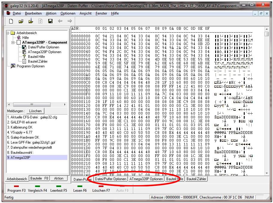
Hexadezimal-Anzeige eines Speicherinhalts
galpe32 (V.1.20.4) - [ATmega328P - Daten-P... - C:\Users\Horst Ostholt\Desktop\CT-1.36m_M328_The_Little_t_ST_7565R_AY-AT\Component...\nDatei Bearbeiten Aktion Optionen Fenster Hilfe\nArbeitsbereich Hilfe Programm Optionen\nMeldungen
in „Galep3, Atmega EEPROM / FUSES programmieren.“ · Mikrocontroller und Digitale Elektronik · · Screenshots
-
Datei
Timer_1.txt
'Eeprom Countdown 'Atmega8 '--------------------------------------------------------------------------' $regfile = "m8def.dat" ' BASCOM AVR Steuerdatei für ATmega8 $crystal = 3686400 ' 3,6864 Mhz Quarz '--------------------
in „Countdown Timer EEprom“ · Mikrocontroller und Digitale Elektronik ·