
-
Datei
D4_beispiel.txt
&%1 T16 R0 A L45.209 A (20.0MM SCHRUPP) T17 R0 A L23.718 A (15 GRAD) P1 =-25.0 P2 =850.0 % (&%1/000000"100 K-SITZ40D20.0+15GRAD) N1 G90 G64 N5 T16 G17 N10 S+1600 F1600 M3 N15 M8 N20 G1 Z100.0 N25 G1 X0.0 Y0.0 N30 G1 X= P1 F400 N35 G1 Z-20.0 N40 G1 Y-7.0 ... ... ... N185 G1 Y7.84 N190 G1 X= P1 N195 G1 Z100 F2000 N200 G1 X0 Y0 N205 M30 ? 0000
in „FreeCAD - CAM PostProcessor für Deckel FP3 mit Contour 3 bzw Dialog 4 Steuerung“ · Mechanik, Gehäuse, Werkzeug ·
-
Datei
nex_4_pwm.vhd
library IEEE; use IEEE.STD_LOGIC_1164.ALL; use ieee.numeric_std.all; entity nex_4_pwm is Port( clk : in std_logic; -- clock led : out std_logic_vector(15 downto 0); sw : in std_logic_vector(15 downto 0); RGB1_Red : out std_logic; RGB1_Green : out std_logic; RGB1_Blue : out std_logic ); end nex_4_pwm; architecture Behavioral of nex_4_pwm is signal pwm_zaehler: unsigned(15 downto 0):=(others => '0'); begin led <= sw; RGB1_Red <= '1' when pwm_zaehler <= unsigned(sw); RGB1_Green <= '1' when pwm_zaehler
-
Datei
4BilderEinWort.cpp
#include <stdio.h> #include <stdlib.h> #include <string.h> #include <ctype.h> #define MAXLEN 13 FILE *dict; int words = 0; char* cleanString(char string[]){ char temp [MAXLEN]; int i = 0; for(i = 0; string[i] != '\0'; i = i + 1){ if(string[i] != '\n' && string[i] != '\r'){ temp[i] = toupper(string[i]); } } temp[i] = '\0'; return temp; } bool checkForLetters(const char letters[], const char string[]){ int i = 0; int j = 0; //Prüfe ob jeder Buchstabe in string auch in letter enthalten ist for(i = 0; i <= strlen(string); i = i + 1){ if(strchr(letters, string[i]) == NULL){ return false; } } return
-
Datei
grab4HA.py
[2]="st4" temperature3_name[3]="000 000" temperature3_name[4]="xxx" #oder 000 003 temperature3_name[10]="Stoe_str" sensors3 = [1, 2, 4] sensorsx = [1] temperature4_name=["unknown"]*10 temperature4_name[0]="072 004 in bereitschaft" temperature4_name[1]="0" temperature4_name[2]="0" temperature4_name[3]="0" temperature4_name[4]="0" temperature5_name=["unknown"]*10 temperature5_name[0]="072 000 in bereitschaft" temperature5_name[1]="0" temperature5
-
Datei
4_Relais_MCUmode.txt
from * Alexa-powered devices like the Amazon Echo or the Dot. * * 7 devices to be discovered: * * 4 Simple WeMo devices * ==> Light1 ==> Relay 1 ==> NodeMCU D5 * ==> Light2 ==> Relay 3 ==> NodeMCU D7 * ==> Outlet1 ==> Relay 2 ==> NodeMCU D6 * ==> Outlet2 ==> Relay 4 ==> NodeMCU D8 * * 3 Groups of devices
in „MCU Mode Programm mit Taster steuern“ · Mikrocontroller und Digitale Elektronik ·
-
Datei
CIC4Stage.vhd
0); oNewValue : out std_logic; oCIC : out std_logic_vector (BIT_WIDTH-1 downto 0) ); end entity CIC4Stage; architecture Behaviour of CIC4Stage is type CICStateType is (idle, get_value,fill, int1, int2, int3, int4); type CombStateType is (idle, get_integrator,calc1,calc2,calc3,calc4,output); type IntCombArray
-
Datei
Pr4_Potentionmeter.txt
unsigned char digit; unsigned char AnalogWert; unsigned char WertASCII[5]; /*WertASCII[1]='.'; WertASCII[4]='V'; WertASCII[5]='\n';*/ while(1) { int digit = get_ADCvalue(); AnalogWert = (digit*500)/1023; WertASCII[4]= ' '; WertASCII[3]= 'V'; WertASCII[2]= (AnalogWert%10)+48; AnalogWert = AnalogWert/10; WertASCII
in „Spannungswerte als ASCII in serielle Monitor darstellen, UART“ · Mikrocontroller und Digitale Elektronik ·
-
Datei
nrf24_4.txt
:68:70:53:54:53:81:BA [2022-03-12 09:18:29.326] 3 11 68:43:51:70:01 15:70:51:43:68:70:53:54:53:FF:C4 [2022-03-12 09:18:29.338] 3 11 68:43:51:70:01 15:70:51:43:68:70:53:54:53:FF:C4 [2022-03-12 09:18:29.347] 3 11 68:43:51:70:01 15:70:51:43:68:70:53:54:53:FF:C4 [2022-03-12 09:18:34.534] 61 11 90:65:23:
in „Wechselrichter Hoymiles HM-xxxx 2,4 GhZ Nordic Protokoll?“ · Mikrocontroller und Digitale Elektronik ·
-
Datei
core_cm4.h
/**************************************************************************//** * @file core_cm4.h * @brief CMSIS Cortex-M4 Core Peripheral Access Layer Header File * @version V4.30 * @date 20. October 2015 ******************************************************************************/ /* Copyright
in „STM32F3 FPU Aktivieren/Benutzen in STM32CubeIDE“ · Mikrocontroller und Digitale Elektronik ·
-
Datei
digit4_demo.c
fuehrender Nullen digit4_setdez(12345, 1); _delay_ms(3); seg7_4digit[7]= d4char_d; _delay_ms(2500); digit4_clr(); // Bsp. fuer Anzeige von 15.0 Grad Celcius digit4_setdez8bit(15,4); digit4_setdp(4); _delay_ms(3); seg7_4digit[3]= ~led7sbmp[0]; seg7_4digit[2]= d4char_oo; seg7_4digit[1]= d4char_C; _delay_ms(2500); digit4_clr(); // Ausgabe blinkender "Hallo"-Text for (i= 0; i< 3; i++) { digit4_puts(&hallo_str[0],6); _delay_ms(500); digit4_clr(); _delay_ms
in „7-Segment Anzeige“ · Mikrocontroller und Digitale Elektronik ·
-
Datei
Wii_Nunchuk_4.asm
; .include "Header_Wii_Nunchuk.h" ;Label und Werte Zuweisungen .include "Hardware_Wii_Nunchuk.h" ;Hardware Label Zuweisungen ; ;Programmstart nach RESET ( Interrupt Vektoren Tabelle ) ; .CSEG ;Was ab hier folgt kommt in den FLASH-Speicher .ORG $0000 ;Programm beginnt an der FLASH-Adresse 0x0000 rjmp _reset ;RESET-Vector .include "IRQm8_Wii_Nunchuk.inc";Restliche Interrupt Vektortabelle .ORG INT_VECTORS_SIZE ;Programmadresse nach den ganzen IRQ-Vektoren ; ;IIIIIIIIIIIIIIIIIIIIIIIIIIIIIIIIIIIIIIIIIIIIIIIIIIIIIIIIIIIIIIIIIIIIIIIIIIIIII ;IIIIIIIIIIIIIIIIIIIIIIIIIIIIIIIIIIIIIIIIIIIIIIIIIIIIIIIIIIIIIIIIIIIIIIIIIIIIII
in „AVR8ASM TWI Interrupt“ · Mikrocontroller und Digitale Elektronik ·
-
Datei
Main_TWI_4.asm
entprellt unbetaetigt .equ key.actuated = 3 ;Taster entprellt betaetigt ;.equ = 4 ; ;.equ = 5 ; ;.equ = 6 ; ;.equ = 7 ; ; ;.include "Hardware.inc" ;Hardware Label Zuweisungen ;******************************************************************************* ;* Hardware Zuweisungen ;
in „AVR8ASM TWI Interrupt“ · Mikrocontroller und Digitale Elektronik ·
-
Datei
4Bit_0108.asm
*** ;* Initialisierungstest fuer LCD-Anzeige ;* mit KS0066U-(ST7066)-kompatiblem Controllerchip ;* 4-Bit-Modus ;* Daten-/Steuerbits auf PORTB, Bit D4 bis D7 ;* Enableimpuls auf PORTD, Bit D0; (bzw. PORTB, hier ausgeremt) ;* RS auf PORTD, Bit D1; (bzw. PORTB, hier ausgeremt) ;* R/WQuer auf Masse fest
in „OLED Display W204-XLG von electronic Assembly“ · Mikrocontroller und Digitale Elektronik ·
-
Datei
count4bit.vhd
std_logic_vector (1 to 8); D9, D11: out std_logic; C: out std_logic ); end entity count4bit; architecture behavior of count4bit is signal ClkLeft : std_logic := '0'; signal ModeLeft, ModeRight: std_logic_vector (1 downto 0); signal count4: std_logic_vector(3 downto 0) := "0000"; signal dir1
-
Datei
lcd_4bit.c
LATDbits.LATD2=1; // RS auf High setzen LCD_Ausgabe(ucDaten); // High-Nibble senden LCD_Ausgabe(ucDaten<<4 ); // Low-Nibble senden, deshalb um 4 Bits links schieben __delay_us(45); // Laut LCD Datenblatt min. 40us Bearbeitungszeit } /* Ausgabe von Kommandos/Befehle an das Display Funktionsübergabe: unsigned
in „Problem mit VS1053“ · Mikrocontroller und Digitale Elektronik ·
-
Datei
lcd_4bit.h
/* * File: i2c_lcd_4bit.h * Author: Sasch * * Created on December 25, 2018, 3:20 PM */ #ifndef I2C_LCD_4BIT_H #define I2C_LCD_4BIT_H #ifdef __cplusplus extern "C" { #endif // Portbelegung des LCD-Display`s // BTG Board Display
in „Problem mit VS1053“ · Mikrocontroller und Digitale Elektronik ·
-
Datei
WischerN-4.txt
'********************************************* ' Scheiben wischer N° 4 '********************************************* $regfile = "2313def.dat" $crystal = 4000000 ' unkritisch $hwstack = 40 $swstack = 16 $framesize = 32 Declare Sub Rut_alt() '* Wechsel Declare Sub Rut_1(
in „Scheibenwischer mit Bascom“ · Mikrocontroller und Digitale Elektronik ·
-
Datei
double64-4.diff
avr4 avr5 avr51 avr6 avrxmega2 avrxmega3 avrxmega4 avrxmega5 avrxmega6 avrxmega7 avrtiny tiny-stack short-calls - -MULTILIB_REQUIRED = \ - msp8 \ - mmcu=avr25 \ - mmcu=avr25/msp8 \ - mmcu=avr3 \ - mmcu=avr31 \ - mmcu=avr35 \ - mmcu=avr4 \ - mmcu=avr5 \ - mmcu=avr51 \ - mmcu=avr6 \ - mmcu=avrxmega2 \ - mmcu=avrxmega3/mshort-calls \ - mmcu=avrxmega3 \ - mmcu=avrxmega4 \ - mmcu=avrxmega5 \ - mmcu=avrxmega6 \ - mmcu=avrxmega7 \ - mmcu=avrtiny
in „64 Bit float Emulator in C, IEEE754 compatibel“ · Projekte & Code ·
-
 Bild
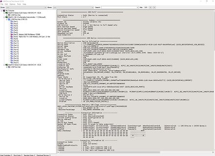
Screenshot von Windows Geräte-Manager USB-Informationen
USB Device Tree Viewer V3.8.6 USB Port? : : :
in „Arduino UNO R4 in Win10 nicht erkannt“ · Mikrocontroller und Digitale Elektronik · · Screenshots
-
Datei
WordClock4.c
/* * WordClock4.c * * Created: 24.06.2014 22:38:59 * Author: Gockel * * Version 0.4 * noch zu Implementieren ADC Auswertung/ Faden * Änderung von Zeilenausgabe zu Spaltenausgabe weil Mosfeteinsatz * Features Verbessertes
in „Atmega16 PortD“ · Mikrocontroller und Digitale Elektronik ·
-
Datei
COM_4_Paul.txt
Beginne Messung... Gemessene Pulse in 10 Millisekunden: 36 Beginne Messung... Gemessene Pulse in 10 Millisekunden: 35 Beginne Messung... Gemessene Pulse in 10 Millisekunden: 36 Beginne Messung... Gemessene Pulse in 10 Millisekunden: 35 Beginne Messung... Gemessene Pulse in 10 Millisekunden: 35 Beginne Messung... Gemessene Pulse in 10 Millisekunden: 36 Beginne Messung... Gemessene Pulse in 10 Millisekunden: 36 Beginne Messung... Gemessene Pulse in 10 Millisekunden: 35 Beginne Messung... Gemessene Pulse in 10 Millisekunden: 35 Beginne Messung... Gemessene Pulse in 10 Millisekunden: 36 Beginne Messung
-
Datei
lorenzRK4.m
function lorenzRK4() %%%%% % Set Lorenz % parameters %%%%% a=10.0; b=8.0/3.0; c=28.0; %%%%%%%%%%% % Set initial condition, step length % and number of steps %%%%%%%%%%% y1(1)=0; y2(1)=1.000; y3(1)=0.0; h=0.01; xM=40; h2
-
Datei
absolute_beginner_4.c
Auslieferungszustand lassen! Ein- und Ausgänge PORT B 0 (14) = PORT B 1 (15) = PORT B 2 (16) = PORT B 3 (17) = PORT B 4 (18) = PORT B 5 (19) = PORT B 6 ( 9) = PORT B 7 (10) = PORT C 0 (23) = PORT C 1 (24) = PORT C 2 (25) = PORT C 3 (26) = PORT C 4 (27) = PORT C 5 (28) = PORT D 0 ( 2) = Anschluss 11 am LCD = DB4 PORT D 1 ( 3) = Anschluss 12 am LCD = DB5 PORT D 2 ( 4) = Anschluss 13 am LCD = DB6 PORT D 3 ( 5) = Anschluss 14 am LCD = DB7 PORT D 4 ( 6) = Anschluss 4 am LCD = RS PORT D 5 (11) = Anschluss 6 am LCD = E Enable PORT D 6 (12) = PORT D 7 (13) = */ // Main.c
in „[[C] LCD die 10000ste“ · Mikrocontroller und Digitale Elektronik ·
-
Datei
4_testv24.asm
= CPUFrequenz /2 / 4800bd * 16 ; = 40 ACIA teilt nochmals durch 16 ; ; Modusregister A9h ; ; 7 6 5 4 3 2 1 0 ; I I I I I I I I ; I I I I I I I 0 = Relais 0 ; I I I I I I 0 x = Relais 1 ; 0 0 0 0 0 1 x x = Modus 2 20mA ; 0 1 0 0 1 0 x x = Modus 3 V24 ; x x 0 1 0 0 x x = Modus 4 DTR ; 1 0 1 0 0 0 x x
in „Suche MOPPEL Projekt in Heft oder .PDF“ · Mikrocontroller und Digitale Elektronik ·
-
PDF
master-slave4.pdf
R GND GND GND C GND R7 C 51k 1 +5V 3 VO VI 1 + C5V 6 C +5V 0 R VCC 3 V IC6A R 51k V C 1 78IC5 10µ 4 1 27k 1 C+5V 2 R3 Q1 V GND 11MC33079P BS250 10k 1 10k 5 GND R 1 4 R 0 K1 GND 3 4 1JS-M1F-12V-5 GND D 1 NO NC MC3307P haben die gleiche beschaltung wie TS914 2 K1 C GND GND
in „Master-Slave-Schaltung, OpAmp stirbt ständig“ · Analoge Elektronik und Schaltungstechnik ·
-
PDF
main4_1.pdf
V + X38 + C15 1 2 6 1uF - 10uF 3 7 4 8 5 5 9 + GND GND + IC2 + 1 16 GND u C 3 14 + 1 u 1 4 13 - 1 C 5 12 u 1 u - 6 11 RX 1 C 1 u 7 10 TX - 1uF - 10uF 1 8 9 u 1 C14 + GND
in „Bitte um kurze Schaltungsansicht“ · Mikrocontroller und Digitale Elektronik ·
-
Datei
Test_Graphik_4.c
/* * Test_Graphik_4.c * * Created: 22.03.2015 13:15:43 * Author: AS */ /* * Copyright: Fabian Maximilian Thiele mailto:me@apetech.de * Author: Fabian Maximilian Thiele * Remarks: this Copyright must be included * known
in „Display mit Controller KS0108 - Welche Datein?“ · Mikrocontroller und Digitale Elektronik ·
-
Datei
danceswithferrets4n.ino
kPin_A0, (addr & 1)?HIGH:LOW); digitalWrite(kPin_A1, (addr & 2)?HIGH:LOW); digitalWrite(kPin_A2, (addr & 4)?HIGH:LOW); digitalWrite(kPin_A3, (addr & 8)?HIGH:LOW); digitalWrite(kPin_A4, (addr & 16)?HIGH:LOW); digitalWrite(kPin_A5, (addr & 32)?HIGH:LOW); digitalWrite(kPin_A6, (addr & 64)?HIGH:LOW); digitalWrite
in „Altes EPROM auslesen Intersil 6654A (2xCE) mit Arduino“ · Mikrocontroller und Digitale Elektronik ·
-
Datei
UNO_R4.txt
dfu-util 0.11-arduino4 Copyright 2005-2009 Weston Schmidt, Harald Welte and OpenMoko Inc. Copyright 2010-2021 Tormod Volden and Stefan Schmidt This program is Free Software and has ABSOLUTELY NO WARRANTY Please report bugs
in „Arduino UNO R4 in Win10 nicht erkannt“ · Mikrocontroller und Digitale Elektronik ·
-
Datei
ZeitmesserV4.ino
#include "heltec.h" #include <WiFi.h> #define DISPLAY_WIDTH 128 #define DISPLAY_HEIGHT 64 #define IMPULSE_DURATION 1000 // Dauer des Impulses in Millisekunden (1000ms) #define IMPULSE_OUTPUT 2 // GPIO-Pin für den Impuls #define POTI_PIN 1 // GPIO-Pin für das Poti #define MEASUREMENT_DELAY 500 // Verzögerung für die Messung von min und max RSSI in Millisekunden #define RESET_DELAY 500 // Verzögerung für das Zurücksetzen der minimalen und maximalen RSSI-Werte const char* ssid = "Mugen MBX8"; const char* password = "12345678"; int rssiValues[DISPLAY_WIDTH] = {0}; // Array für RSSI-Werte int currentIndex
in „Rundenzeitmesser auf Basis RSSI für RC Fernsteuerung“ · Mikrocontroller und Digitale Elektronik ·
-
Datei
sql_test4.php
<!DOCTYPE html> <html lang="de-de"> <head> <script src="https://ajax.googleapis.com/ajax/libs/jquery/3.6.0/jquery.min.js"></script> <script type="text/javascript" src="https://www.gstatic.com/charts/loader.js"></script> <script type="text/javascript"> google.load("visualization", "1", {packages:["corechart"]}); google.setOnLoadCallback(drawChart); function drawChart(json) { var werte = new google.visualization.DataTable(json); var style = { }; var chart = new google.visualization.LineChart(document.getElementById("linechart")); chart.draw(werte, style); setInterval(function() { $.ajax({ url: './chartarray.php
in „Werte aus MySQL für Google Charts werden nicht aktualisiert“ · Softwareentwicklung ·
-
Datei
komparator_4_bit.vhd
LIBRARY IEEE; USE IEEE.STD_LOGIC_1164.ALL; entity KOMPARATOR_4_BIT is port ( X : in std_logic_vector(3 downto 0); Y : in std_logic_vector(3 downto 0); GROESSER : out std_logic; KLEINER : out std_logic; GLEICH : out std_logic ); end entity KOMPARATOR_4_BIT ; architecture
-
PDF
Bewegungsmelder_V4.pdf
R24 47k D11 470k 20k 1% D10 VR2 R37 R34 - Schaltsignal 504 1,2M - 100k D9 zum Trans. LM324 LM324 34 4/4 Lastrelais + + R22 301k 1% R35 R30 C27 C22 391k 104 1% 9,09k 104 LDR 1% +5V +5V +5V Meter / Dist R14 R18 + D6 R27 R36 o LM324 150K R17 VR1 30K 1/4 30k 1M 1% 270K 105 R36u - D8 100k C21 R19 473 12K Time C17 + D7 R29 C25 47uF 5k1 4,7uF LM324 - 2/4 C19 LM358 471 2/2 - VR3 R38 205 2k Q3 Q3 + C1815 C1815 R15 C ldr R20 C23 D12 100K 47uF 18K 47uF R28 1% 60 1% +5V + R3 10k LHI878 LHI878 C14 LM358 471 1/2 R8 R5 R7 R4 18K 10K 18K 10K -
in „Bewegungsmelder PEHA 896.23 Schaltplan“ · Analoge Elektronik und Schaltungstechnik ·
-
PDF
_Messung_mit_URV_4.pdf
R&S HF- Millivoltmeter 10kHz … 2GHz URV 4 (292.5012.02) URV 4 292.5012.02 mit Tastkopf Tastkopf : R&S 243.8811.02 0,1 … 1000MHz/ 2,5pF R&S 243.8811.02 0,1 … 1000MHz/ Zum NULL Abgleich die Tastkopfspitze zur Abschirmung in C ca. 2,5pF Lötzinnrolle
in „Verständnisfrage HF-Tastkopf für URV Millivoltmeter“ · HF, Funk und Felder ·
-
PDF
GPS_ublox_4.pdf
Die Umrüstung eines Nano V3.0 auf 3.3V-Logik, für GPS ublox Ich habe angefangen, mal mit GPS herumzuspielen. Ein Modul mit ublox NEO 6 gabs für 18€. Das war innerhalb von 3 Tagen, ab deutschem Lager, bei mir. Für die Verbindung des ublox zum USB braucht man noch einen USB-RS232 Koppler mit 3,3 V- Ausgangssignalen. Dazu bot sich ein Arduino Nano V3.0-Clone mit einem CH340 als USB-Zugang an. Die werden derzeit so billig wie Vortagssemmeln angeboten. Nur haben die einen 5V-Regler auf der Platine, sind also für den ublox nicht verwendbar. Die Umrüstung auf 3,3 V ist aber relativ einfach: Der 5,0V-Spannungsregler
-
PDF
EA_4_40.pdf
Stand 04.2011 DOTMATRIXDISPLA YS 4 X 40 4 Zeilen à 40 Zeichen Artikel- Zeich. Modulmaße SichtfensteAnschlußahmen Hinweise Maße bezeichnung höhe B H T B H Zubehör Seite EA W404B-NLW 4.9 190.0 54.0 13.0 147.0 29.52x8+2 017-13U neg. blau
in „Cursor setzen LCD Display“ · Mikrocontroller und Digitale Elektronik ·
-
PDF
pwrmon4.sch.pdf
pwrmon4.sch.pdf
in „erste Schritte: AC-Messungen mit AVR“ · Mikrocontroller und Digitale Elektronik ·
-
PDF
4_Sender_schema.pdf
3=GND D PC1(ADC1) 24 5 5 N 22 GND PC2(ADC2) 25 100n + + C G 21 AREF PC3(ADC3) 26 + C3 V 20 AVCC PC4(ADC4/SDA) 27 GND +5V PC5(ADC5/SCL) 28 10u D G 9 PB6(XTAL1/TOSC1) N GND GND 10 PB7(XTAL2/TOSC2) PD0(RXD) 2 1 1 O12 PD1(TXD) 3 2 2 11 N PD2(INT0) 4 3 3 10 G C2 8 GND PD3(INT1) 5 4 4 9 PD4(XCK/T0) 6 5 5
in „Sender für Funkfernsteuerung für Dorma-Torantriebe, z.B. Modell HS43“ · Projekte & Code ·
-
PDF
Elektronische_Last_4.pdf
9 X101-3 16k2 1 4 4 4 4 100n 100n 100n 100n 100n GND TLC274P N 5 IC103B GND +10V +5V G 7 D103 6 B BAT42 TLC274P B X102-1eil -5V GNDV X102-2 N -5V X102-3 V G GND 6 D105 +5V X102-4 - 1 K101 MUR3040PT V+ X102-5 V+ 8 ISET
in „Elektronische Last: Referenz für ADC und DAC“ · Analoge Elektronik und Schaltungstechnik ·
-
PDF
ADF4360-4.pdf
device. t4 t5 CLOCK t t 2 3 DATA DB23 (MSB) DB22 DB2 DB1 DB0 (LSB) (CONTROL BIT C2) (CONTROL BIT C1) 7 LE t 1 6 0 LE 4 0 Figure2.TimingDiagram Rev. B | Page 5 of 24 ADF4360-4 DataSheet ABSOLUTE MAXIMUM RATINGS
in „SPI-Schnittstelle Befehl: SPI_I2S_SendData(spi2, data)“ · Mikrocontroller und Digitale Elektronik ·
-
PDF
Messungen_am_Digitalvoltmeter_4.pdf
Messungen am Digitalvoltmeter 4,5 Stellig ICL 7135 Trafo era BV 038-5187.0F 220V / 6V 3,2VA Eingansspannung Ue=9,28V (gemessen an Spannungsregler) Ausgangsspannung Ua= 5,04V (gemessen an Spannungsregler)
in „Projekt DVM 4,5 Digit aus Standardbauteilen mit automatischer Bereichsumschaltung“ · Analoge Elektronik und Schaltungstechnik ·
-
PDF
ELO_4_1981.pdf
ELO_4_1981.pdf
in „ELO Universalzähler 1000MHz“ · Analoge Elektronik und Schaltungstechnik ·
-
PDF
GDS_Laboruebung_4.pdf
Beuth Hochschule Berlin FB VI, Labor für Digitaltechnik GDS: Laborübung 4 Realisierung eines Addier-/Subtrahierwerks für zwei vorzeichenlose 4-Bit Zahlen In diesem Laborversuch soll ein programmierbarer Logikbaustein (programmable logic device = PLD) benutzt werden, um ein
in „4bit Volladdierer/Subtrahier PLD (GAL22V10B) mit umschalter“ · FPGA, VHDL & Co. ·
-
PDF
regression_4ter.pdf
100 120 140 160 180 200 170 28900 4913000 835210000 828 835,3 175 30625 5359375 937890625 856 851,4 180 32400 5832000 1049760000 870 862,4 y y' RGP -1,12489E-06 58,48E-06 73,52E-03 -4,26E+00 87,08E+00 #NV 3,14672E-07 130,04E-06 18,67E-03 1,08E+00 20,72E+00 #NV 0,999716787 5,36E+00 #NV #NV #NV #NV Seite
in „ADC Spannungsumwandlung in Temperatur Fehler?“ · Mikrocontroller und Digitale Elektronik ·
-
PDF
EA_4_40.pdf
Stand 04.2011 DOTMATRIXDISPLA YS 4 X 40 4 Zeilen à 40 Zeichen Artikel- Zeich. Modulmaße SichtfensteAnschlußahmen Hinweise Maße bezeichnung höhe B H T B H Zubehör Seite EA W404B-NLW 4.9 190.0 54.0 13.0 147.0 29.52x8+2 017-13U neg. blau
in „LCD Display Treiber und Einkopplungen“ · Mikrocontroller und Digitale Elektronik ·
-
PDF
hv-supply4.pdf
16SMD D 1 R11 2 1 k T2 R16 I-messung (high) IREF R 2 IRF820 T4 10k OPA1013D F 1k 5 L 12V . sind 3.5Ohm 200mA.abfall 7 6 M GND Strombegrenzung 3 5 23.5Ohm (47/2) einem Spannungs- 4 4 C 7 D2 R 3 abfall von 4.7V 0 4 0 maxP ist dann 110W R6 1 N N TP1 +5V D 15 IC2B D31 R10 T3 3 9 ISOVIN VDD 2 UMON R7k 7 IRF820 K2 W W 8 9 6 0 2 4 / / VOUT 3 IMON UREF 10k 4 D OPA1013D R 4 R 4 D 4 L 4 8 ISOGND GND 1 N 1 E R 1 G n 5 7 ISO-Board . C 0 0 0 W 4 4 2 2 3 / U$2 1 GND R 2 1 M ISO-BOARD R 1 W D6 GND / UOUT 9 M R 1 L C1 E M 220n/1600V 0
in „Strom in Kaskode??“ · Analoge Elektronik und Schaltungstechnik ·
-
PDF
-
PDF
ATmegaXX4.pdf
0.0% 32 -1.4% 64 0.2% 57.6k 16 2.1% 34 -0.8% 19 0.0% 39 0.0% 21 -1.4% 42 0.9% 76.8k 12 0.2% 25 0.2% 14 0.0% 29 0.0% 15 1.7% 32 -1.4% 115.2k 8 -3.5% 16 2.1% 9 0.0% 19 0.0% 10 -1.4% 21 -1.4% 230.4k 3 8.5% 8 -3.5% 4 0.0% 9 0.0% 4 8.5% 10 -1.4% 250k 3 0.0% 7 0.0% 4 -7.8% 8 2.4% 4 0.0% 9 0.0% 0.5M 1 0.0% 3 0.0% – – 4 -7.8% – – 4 0.0% 1M 0 0.0% 1 0.0% – – – – – – – – Max. (1) 1 Mbps 2 Mbps 1.152 Mbps 2.304 Mbps 1.25 Mbps 2.5 Mbps
in „Atmega644PA Timer3“ · Mikrocontroller und Digitale Elektronik ·
-
PDF
TJA1055_4.pdf
(lp) HIGH-level output voltage in low-power mode on pinERR IO= −100 A VCC − 1.1 V CC − 0.7 V CC− 0.4 V on pin RXD IO= −100 A VCC − 1.1 V CC − 0.7 V CC− 0.4 V V OL LOW-level output voltage IO= 1.6 mA 0 - 0.4 V I = 1.2 mA; V < 4.75 V 0 - 0.4 V O CC IO= 5 mA 0 - 1.5 V Pins RXD and ERR (TJA1055T/3) IOL
in „TJA1055T VBAT und VCC - CAN Bus“ · Mikrocontroller und Digitale Elektronik ·
-
PDF
IDEALDIODE4_1_.pdf
D G S 4.25V PMV65XP Q1 4.2V 2 AMPS MAX DC IN D S 15V MAX G 200.0K 205K 10K 1% A1 R5 1% R4 2 3 2.1v R1 + 1 TLV2401 _ 4 + 470pF LITHIUM ION C1 5 OR NiMH 2.2M 200.0K BATTERY 0.1uF 1% R3 C2 R6 200.0K 1% 5 R2 1 IDEAL
in „Powerbank Meinung.“ · Analoge Elektronik und Schaltungstechnik ·
