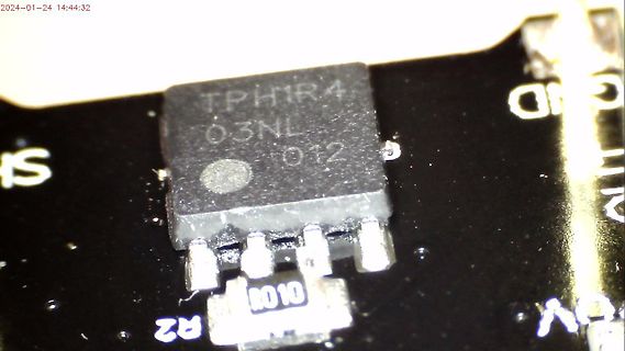
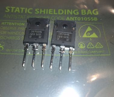
STATIC SHIELDING BAG
ANTISTAT REORDER CODE ANT010SSB
ATTENTION
OBSERVE PREC
FOR HANDLIN
ISCHARGE S
IRFP064N
1YR 503L
CF OC
ANTISTAT.COM
AG IS RoHS COMPLIANT
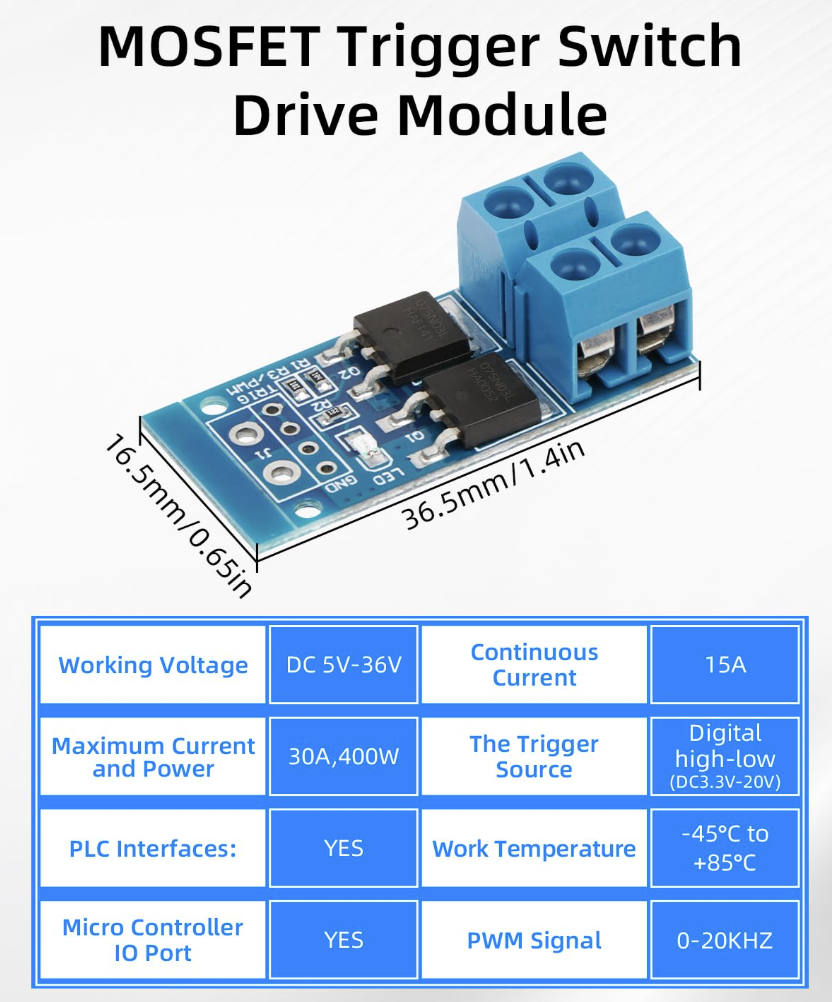
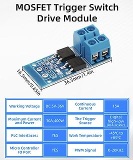
MOSFET Trigger Switch Drive Module 16.5mm/0.65in 36.5mm/1.4in R1 R3 PWM Q2 LED1 LED2 LED3 GND Working Voltage DC 5V-36V Continuous Current 15A Maximum Current and Power 30A,400W The Trigger Source Digital
voltage sensed via R5 and the FWD pin of the IC. In continuous conduction mode operation, the power MOSFET is turned off just prior to the secondary-side controller commanding a new switching cycle from the primary. In discontinuous mode the MOSFET is turned off when the voltage drop across the MOSFET falls below ground. Secondary-side control of the primary-side MOSFET ensures that it is never on simultaneously with the synchronous rectification MOSFET. The MOSFET drive signal is output on the SR pin. The secondary-side of the IC is self-powered from either the secondary
JIANGSU CHANGJIANG ELE CTRONICS TECHNOLOGY CO., LTD SOT-23 Plastic-Encapsulate MOSFETS AO3401 P-Chan nel Enhanceme t Mode Field Ef fectT ransistor V (BR)SS R DS(on)MAX D SOT-23 65m Ω @-10V -30V 75mΩ @-4.5V -4.2A 1. GAT 90m Ω @-2.5V 2. SOURCE 3. DRAIN FEATURE APPLICA TION z High dense
SMK0825F Advanced N-Ch Power MOSFET SWITCHING REGULATOR APPLICATIONS Features PIN Connection • High Voltage : BV DSS=250V(Min.) D • Low C rss C rsspF(Typ.) • Low gate charge : Qg=14.5nC(Typ.) • Low R DS(on) RDS(on)0.43Ω(Max.) G Ordering
PD - 91541B IRLR/U120N ® HEXFET Power MOSFET l Surface Mount (IRLR120N) D l Straight Lead (IRLU120N) V DSS = 100V l Advanced Process Technology l Fast Switching R = 0.185 l Fully Avalanche Rated DS(on) G Description ID= 10A FifthGenerationHEXFETsfromInternationalRectifier
PD - 91749 PRELIMINARY IRFR/U6215 ® HEXFET Power MOSFET l P-Channel D l 175°C Operating Temperature VDSS = -150V l Surface Mount (IRFR6215) l Straight Lead (IRFU6215) R = 0.295 l Advanced Process Technology DS(on) G l Fast Switching l Fully Avalanche Rated
The G5177C is a compact, high-efficiency, synchro- 3.3V Input nous step-up converter with power Mosfets embedded Low 70μA Quiescent Current and with output turn off true shutdown function and Guaranteed 3A Output Current at V OUT= 5V adjustable output current limiting with foldback for a 500KHz PV WM
SUM110P04-05 Vishay Siliconix P-Channel 40-V (D-S) MOSFET PRODUCT SUMMARY FEATURES • TrenchFET Power MOSFET VDS (V) rDS(on)(Ω) ID(A)a Q gTyp.) RoHS - 40 0.005 at GS = - 10 V - 110 185 nC COMPLIANT TO-263 S G Drain Connected to Tab G D S Top View D Ordering Information: SUM110P04-05-E3 (Lead (Pb)-free) P-Channel MOSFET ABSOLUTE MAXIMUM RATINGS T = 25 °C, unless otherwise noted A Parameter Symbol Limit Unit V Drain-Source Voltage DS - 40 V Gate-Source Voltage V GS ± 20 TC = 25 °C - 110a TC= 70 °C - 110a Continuous
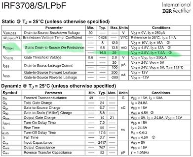
PD - 93938B IRF3708 SMPS MOSFET IRF3708S IRF3708L Applications ® Q High Frequency DC-DC Isolated Converters HEXFET Power MOSFET with Synchronous Rectification for Telecom V DSS R DS(on) max ID and Industrial Use 30V 12mΩ 62A QT High
SUM55P06-19L Vishay Siliconix P-Channel 60 V (D-S) 175 °C MOSFET FEATURES PRODUCT SUMMARY • TrenchFET Power MOSFET d VDS (V) R DS(on)() ID(A) Qg(Typ.) Material categorization: 0.019 at V = - 10 V For definitions of compliance please see - 60 GS - 55 76 0.025 at GS = - 4.5 V - 48 www.vishay.com/doc?99912 S TO-263 G D D G S Top View P-Channel MOSFET Ordering Information: SUM55P06-19L-E3 (Lead (Pb)-free) ABSOLUTE MAXIMUM RATINGS (T = 25 °C, unless otCerwise noted) Parameter Symbol Limit Unit Drain-Source Voltage VDS - 60 V Gate-Source Voltage VGS
PD - 95363 IRF3708PbF SMPS MOSFET IRF3708SPbF IRF3708LPbF Applications ® l High Frequency DC-DC Isolated Converters HEXFET Power MOSFET with Synchronous Rectification for Telecom V DSS R DS(on) max ID and Industrial Use 30V 12mΩ 62A
PD - 95363 IRF3708PbF SMPS MOSFET IRF3708SPbF IRF3708LPbF Applications ® l High Frequency DC-DC Isolated Converters HEXFET Power MOSFET with Synchronous Rectification for Telecom V DSS R DS(on) max ID and Industrial Use 30V 12mΩ 62A
PD - 95363 IRF3708PbF SMPS MOSFET IRF3708SPbF IRF3708LPbF Applications ® l High Frequency DC-DC Isolated Converters HEXFET Power MOSFET with Synchronous Rectification for Telecom V DSS R DS(on) max ID and Industrial Use 30V 12mΩ 62A
AOD522 www.VBsemi.tw N-Channel 30-V (D-S) MOSFET FEATURES PRODUCT SUMMARY ® • TrenchFET Power MOSFET VDS (V) R DS(on)) I (A)a, e Qg(Typ) 100 % R and UIS Tested D g 0.007 at GS = 10 V 50 Compliant to RoHS Directive 2011/65/EU 30 25 nC 0.009 at GS = 4.5 V 40 APPLICATIONS D OR-ing Server TO-252 DC/DC G G D S S Top View N-Channel MOSFET ABSOLUTE MAXIMUM RATINGS (T = 25 °C, unless otAerwise noted) Parameter Symbol Limit Unit Drain-Source Voltage V DS 30 V Gate-Source Voltage V GS ± 20 T = 25 °C C 50 TC = 70 °C 40 Contiuous D ain Current
used: • fast gate 'turn off' • high sink current • low source inductance "fast switch" Look up new MOSFET generations (APT V) 102 Output Capacitance of MOSFETs A study by Simulation • Nested AC analysis • V is swept from 0V to 100V 1 • I ac is set to 1A (not to worry, used after linearization) • Capacitance
JIANGSU CHANGJIANG ELE CTRONICS TECHNOLOGY CO., LTD SOT-23 Plastic-Encapsulate MOSFETS AO3400 N-Ch ann el Enhanceme tnMode Field Ef fect ransistor V (BR)SS R DS(on)AX D SOT-23 35m Ω@10V 30 V 40mΩ @ 4.5V 5.8A 1. GAT 52m Ω @ 2.5V 2. SOURCE 3. DRAIN FEATURE APPLICATION z High dense cell
Latch u.s.w. bis alle 13 Latches gefüllt sind. Die Ebenen werden ja ATMega32 eigentlich durch die Mosfets geschaltet. µC Pinbenutzung: 8 x Datenleitungen für Bitmuster zu den Latches 13 x Latch Enabled 10 x Ebenensteuerung der Mosfets ---------------------------------------------- 31 Pins werden benötigt
Latch u.s.w. bis alle 13 Latches gefüllt sind. Die Ebenen werden ja ATMega32 eigentlich durch die Mosfets geschaltet. µC Pinbenutzung: 8 x Datenleitungen für Bitmuster zu den Latches 13 x Latch Enabled 10 x Ebenensteuerung der Mosfets ---------------------------------------------- 31 Pins werden benötigt
Latch u.s.w. bis alle 13 Latches gefüllt sind. Die Ebenen werden ja ATMega32 eigentlich durch die Mosfets geschaltet. µC Pinbenutzung: 8 x Datenleitungen für Bitmuster zu den Latches 13 x Latch Enabled 10 x Ebenensteuerung der Mosfets ---------------------------------------------- 31 Pins werden benötigt
ASCII Zeichen 0-255 schreiben. 32-255 Buchstaben an Cursorposition zeichnen, Cursor erhöhen. Der OptoMOSFET K1 kann bei LCDs die über einen ONOFF oder DispOFF\ Pin verfügen entfallen. Falls der OptoMOSFET nicht erhältich ist, kann dieser durch einen normalen Optokoppler ersetzt werden, wenn dieser genügend
// Timer 0 starten TCNT0=0xfc; //fc weil nur 3 takte zwischen den beiden } //umschaltzeiten der Mosfets sind // Timer 1 output compare A interrupt service routine ISR(TIMER1_COMPA_vect) { fet1_aus; //FET1 aus t0_ch = 0; // Timer/Counter 0 initialization // Clock source: System Clock // Clock value: 30,753 kHz TCCR0=0x04; TCNT0=0xfc; //fc weil nur 3 takte zwischen den beiden //umschaltzeiten der Mosfets sind } // Timer 0 overflow interrupt service routine ISR(TIMER0_OVF_vect) { TCCR0 = 0; // timer 0 aus if (t0_ch) { fet1_an; //FET2 an } else { fet2_an; //FET1 an } } // ADC interrupt service routine
due to increasing switch losses in the FET's. •The dynamic brake input will turn off the high side MOSFET's and turn on all of the low side MOSFET's causing the motor to produce retarding torque that's proportional to motor speed. This feature would normally not be used in a servo application, except as
shown in Fig. 2.1(c). For Buck and Buck-Boost converters, MOSFET S1 functions as an active switch and MOSFET S2 functions as a SR, and vice versa for the Boost converter, P P P S Cj D S1 Cj1 A A A M M M L L L D S S Cj 2 Cj2 N N N (a) (b) (c) (a) Buck and Buck-Boost
ASCII Zeichen 0-255 schreiben. 32-255 Buchstaben an Cursorposition zeichnen, Cursor erhöhen. Der OptoMOSFET K1 kann bei LCDs die über einen ONOFF oder DispOFF\ Pin verfügen entfallen. Falls der OptoMOSFET nicht erhältich ist, kann dieser durch einen normalen Optokoppler ersetzt werden, wenn dieser genügend
S 9 June1999 9 4 5 D Y Si9945DY* Dual N-Channel Enhancement Mode MOSFET General Description Features These N-Channel Enhancement Mode MOSFETs are 3.3 A, 60 V. R = 0.100 @ V = 10 V produced using Fairchild Semiconductor’s advance DS(ON) GS process that has been especially
MIC94030/94031 Micrel MIC94030/94031 TinyFET™ P-Channel MOSFET Preliminary Information General Description Features The MIC94030 and MIC94031 are 4-terminal silicon gate • 13.5V minimum drain-to-source breakdown P-channelMOSFETsthatprovidelowon-resistanceinavery
Electronics Corp. Revised Date :2009.05.07 Page No. : 1/6 N-Channel Logic Level Enhancement Mode Power MOSFET MTB06N03H8 BV DSS 30V ID 75A R DSON(max) 6.5mΩ Description The MTB06N03H8 is a N-channel enhancement-mode MOSFET, providing the designer with the best combination of fast switching, ruggedized device
Electronics Corp. Revised Date :2009.05.07 Page No. : 1/6 N-Channel Logic Level Enhancement Mode Power MOSFET MTB09N03H8 BV DSS 30V ID 50A R DSON(max) 9.5mΩ Description The MTB09N03H8 is a N-channel enhancement-mode MOSFET, providing the designer with the best combination of fast switching, ruggedized device
use Lithium Ion (LiIon) batteries. Each battery consists of at least a 1 Replace DPDT relay with Mosfet? number of LiIon cells in a series 'string' and may consist of a number of parallel combinations of several series strings. Hot Network Questions A Lithium Ion cell has a maximum charging voltage of
use Lithium Ion (LiIon) batteries. Each battery consists of at least a 1 Replace DPDT relay with Mosfet? number of LiIon cells in a series 'string' and may consist of a number of parallel combinations of several series strings. Hot Network Questions A Lithium Ion cell has a maximum charging voltage of
PD - 97047A IRFB3077PbF Applications HEXFET Power MOSFET l High Efficiency Synchronous Rectification in SMPS l Uninterruptible Power Supply D V DSS 75V l High Speed Power Switching l Hard Switched and High Frequency Circuits R DS(on) typ. 2.8m : Benefits
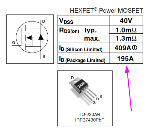
PD -97363 IRLB3034PbF HEXFET Power MOSFET Applications l DC Motor Drive D V DSS 40V l High Efficiency Synchronous Rectification in SMPS R typ. l Uninterruptible Power Supply DS(on) 1.4m : max. 1.7m : l High Speed Power Switching G l Hard Switched
Creating New Symbols Help -> Help Topics ->FAQs -> Third party models Help -> Help Topics ->FAQs -> Mosfet You will find also help in the linked documents from our LTspice Yahoo group. Links Links > Spice Courseware And Tutorials There is another document about symbols and models in our Files section. Files
PD -97363 IRLB3034PbF HEXFET Power MOSFET Applications l DC Motor Drive D V DSS 40V l High Efficiency Synchronous Rectification in SMPS R typ. l Uninterruptible Power Supply DS(on) 1.4m : max. 1.7m : l High Speed Power Switching G l Hard Switched
PD -97363 IRLB3034PbF HEXFET Power MOSFET Applications l DC Motor Drive D V DSS 40V l High Efficiency Synchronous Rectification in SMPS R typ. l Uninterruptible Power Supply DS(on) 1.4m : max. 1.7m : l High Speed Power Switching G l Hard Switched
PD -97143 IRFB3006PbF HEXFET Power MOSFET Applications D V DSS 60V l High Efficiency Synchronous Rectification in SMPS l Uninterruptible Power Supply R DS(on) typ. 2.1m : l High Speed Power Switching max. 2.5m : l Hard Switched and High Frequency

 Bild
 Bild
 Bild
 Bild
 Bild
 Bild
 Bild
 Bild
 Bild
 Bild
 Bild