-
 Bild
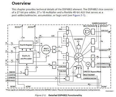
Blockschaltbild der DSP48E2 Funktionalität
DSP48E2 slice consists of a 27-bit pre-adder, 27 x 18 multiplier and a flexible 48-bit ALU that serves as a post-adder/subtractor, accumulator, or logic unit (see Figure 2-1). BCOUT* ACOUT 0 RND W MULTSIGN 0 A PCOUT* XOR OUT 18 30 48 A:B 48 18 18 B 18 DUAL B REGISTER 18 18 MULT 27 X 18 M U ALUMODE 4 18 30
-
Thread
JLCPCB PCBA macht mich Wahnsinnig - Alternative?
kurzer Ausschnitt: Regarding your first question, our process for generating the production draft is as follows: 1. Specialized software identifies all networks (whether connected or disconnected). 2. Our engineering team adjusts the spacing based on the identified networks to ensure the final product
-
Thread
UWB-Arduinos, Wachstumsmarkt Weltraum, XIAO mit WizNet uvam
that does not support the RVA23U64 profile. RVA23U64 [1] is the profile relevant for user space. As there is no upgrade path from Ubuntu 25.04 Plucky for RVA20 systems, we should also stop upgrading these RISC-V systems from Noble to Plucky." [/c] Zu beachten ist, dass derzeit unterstützte RISC
-
 Bild
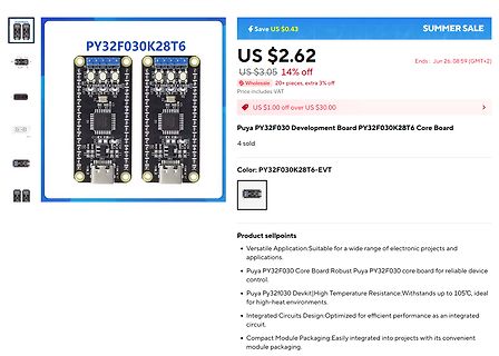
Online-Shop Produktseite für Puya PY32F030 Development Board
ideal for high-heat environments. Integrated Circuits Design: Optimized for efficient performance as an integrated circuit. Compact Module Packaging: Easily integrated into projects with its convenient module packaging.
-
Thread
Neuer dsPIC mit besserem ADC, ESP32-C61 in Serienfertigung, NFC 15 uvam
around a 32-bit RISC-V processor running at up to 160 MHz, the ESP32-C61 supports Wi-Fi 6 features such as OFDMA, MU-MIMO, and Target Wake Time (TWT), ensuring low latency, high concurrency, and power efficiency. Its Bluetooth 5 (LE) capabilities include extended advertising, Coded PHY, and 2 Mbps PHY, as well as support for Bluetooth Mesh 1.1. [/c] Interessant ist, dass Espressif die „Initial-Auslieferung“ anders als im Fall von C5 und P4 (siehe https://www.youtube.com/watch?v=-YYkeAiIejI) nicht an seine
-
 Bild
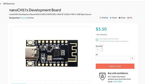
Produktseite nanoCH57x Development Board
Cart Buy with confidence. Our Tindie Guarantee protects your purchase from fraud. Learn More RS 5V AS A5 A1 A0 AB BOOT 6 3V3 A7 A10 A11 A2 A3 AS nanoCH57x
-
Thread
Arduino: page-write in I2C eeprom verliert sporadisch ein Byte
0) bit queued while (Wire.endTransmission() != 0x00); // Transmission success status code as per Wire Library } [/c] Das hat am Verhalten nichts geändert, gefällt mir aber auch besser, als das delay(5). Danach habe ich den Vorschlag von Nemopuk integriert und nach jedem Aufruf von Page_Write
2 Zeichen (= 1Byte) eingetroffen sein. [c] while ((Serial.available() >= 2) || // As long as data are available (receive_timer >0)) { // Or receive timeout is running if (!rx_run){receive_timer=399;rx_run=1;} // Set receive timeout counter (only once
-
Thread
Arduino CH32V003
RCC_APB2PCENR |= (1 << 4); // Set bit 4 (IOPCEN) to enable GPIOC peripheral clock // Configure PC1 as push-pull output, 50MHz GPIOC_CFGLR &= ~(0xF << 4); // Clear configuration bits for PC1 (bits 7:4) GPIOC_CFGLR |= (0x3 << 4); // Set MODE1=11 (output 50MHz), CNF1=00 (push-pull) } void loop
-
 Bild
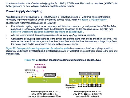
Anleitung zur Entkopplung der Stromversorgung bei STM32 Mikrocontrollern
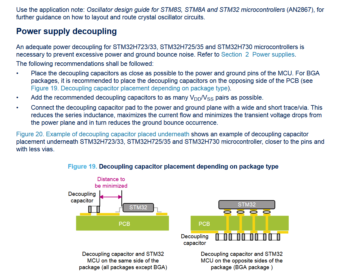
Power supplies. The following recommendations shall be followed: • Place the decoupling capacitors as close as possible to the power and ground pins of the MCU. For BGA packages, it is recommended to place the decoupling capacitors on the opposing side of the PCB (see Figure 19. Decoupling capacitor placement depending on package type). • Add the recommended decoupling capacitors to as many VDD/VSS pairs as possible. • Connect the decoupling capacitor pad to the power and ground via a wide and short trace/via. This reduces the series inductance, maximizes the current flow and minimizes
-
 Bild
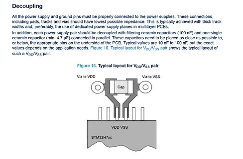
Datenblatt-Ausschnitt zur Entkopplung von VDD/VSS Paaren
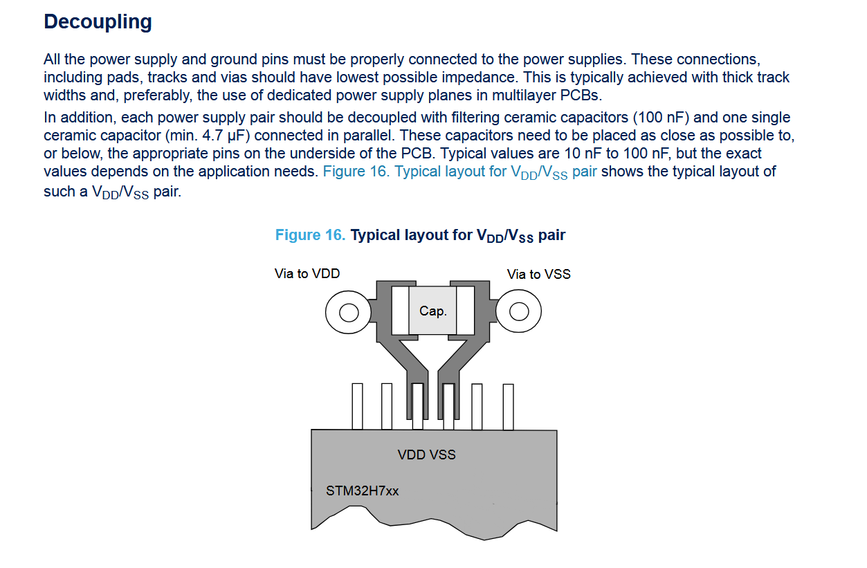
one single ceramic capacitor (min. 4.7 µF) connected in parallel. These capacitors need to be placed as close as possible to, or below, the appropriate pins on the underside of the PCB. Typical values are 10 nF to 100 nF, but the exact values depends on the application needs. Figure 16. Typical layout
-
Thread
Abblockkondensatoren die 99te
board and the NUCLEO-H723ZG and > NUCLEO-H725ZG Nucleo boards are good references that can be used as a > basis for a specific application development. > Details of these boards are available on www.st.com website.
-
Thread
Haben Ameisen einen Spürsinn für Strom?
shorting or by > occupying electrical plugs, connexion boxes or > electro-mechanical devices, such as automatic blinds. Auch die Wikipedia (https://de.wikipedia.org/wiki/Vergessene_Wegameise) weiss zu berichten: > In menschlichen Lebensräumen neigt L. neglectus dazu, > in elektrischen Geräten zu
-
 Bild
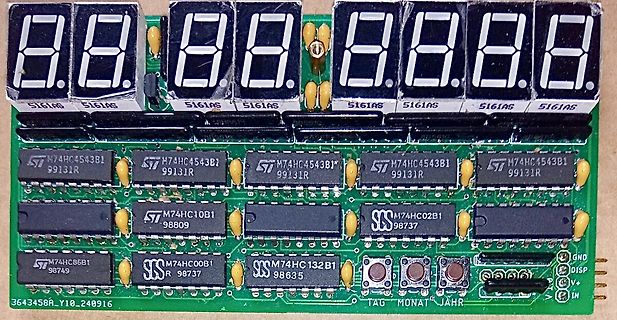
Leiterplatte mit 7-Segment-Anzeigen und Logik-ICs
8.8. 8.8. 8.8.8.8. 5161AS 5161AS 5161AS ST M74HC4543B1 99131R ST M74HC4543B1 99131R ST M74HC4543B1 99131R ST M74HC4543B1 99131R ST M74HC10B1 98809 SS M74HC02B1 98737 ST M74HC86B1 98749 SS M74HC00B1 98737 SS M74HC132B1 98635 3643458A_Y10
-
Thread
TinyAVR Serie 1/2 OneWire Zugriff auf DS18B20 Temperatursensor
Convert the data to integer temperature value return (raw * 10) / 16; // return as integer value xx.x (%10 for decimal place) } [/c] Es müsste doch mittlerweile jemand eine funktionierde OneWire Library für die neuen ATtinys entwickelt haben, die Serie (1/2) ist ja schon einige
-
 Bild
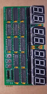
Leiterplatte mit 7-Segment-Anzeigen und Logik-ICs
98737 M74HC132B1 98635 M74HC4543B1 99131R M74HC4543B1 99131R M74HC4543B1 99131R TAG MONAT JAHR 5161AS 5161AS 5161AS IN V+ GND DIO SP
-
 Bild
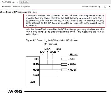
Datenblatt-Ausschnitt zur Verbindung von SPI und ISP Schnittstellen
other than the AVR, that may try to drive the lines. This is especially important with the SPI bus, as it is similar to the ISP interface. Applying series resistors on the SPI lines, as depicted in Figure 4-2, is the easiest way to achieve this. Note that the AVR will never drive the SPI lines in a programming
-
Thread
AMD-AI-Keynote, Amper heruntergeskillt, PCIe 7.0 und AI-Ethernet
darüber, dass sich der Veranstalter-TerInvest zurückziehen möchte: [c] Terinvest will still operate as a company, but will no longer organize trade fairs. [/c] Dies bedeutet allerdings nicht, dass das Hochskillen der Amperes in Zukunft unterbleibt. Die BVV - das Unternehmen ist Eigentümer bzw. Betreiber
supply chain coordination. Taking this as a strategic starting point, Zhaoyi Innovation will accelerate the expansion of the international market and build a more open, flexible and forward-looking ecosystem. [/c] ### Menlo Micro MM5622
-
 Bild
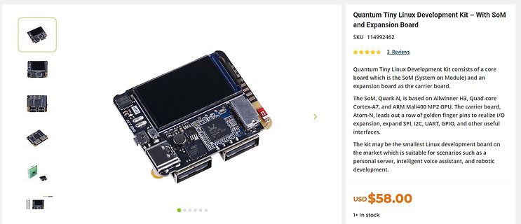
Produktseite Quantum Tiny Linux Development Kit
Development Kit consists of a core board which is the SoM (System on Module) and an expansion board as the carrier board. The SoM, Quark-N, is based on Allwinner H3, Quad-core Cortex-A7, ARM Mali400 MP2 GPU. The carrier board, Atom-N, leads out a row of golden finger pins to realize I/O expansion, expand
-
Thread
ATMega328PB lässt sich nur noch programmieren. Sonst keine Funktion mehr
Stromversorgung und dem Mikrocontroller ohne I2C Sensoren, RS485 Treiber und so weiter. Hab ein neues Projekt in AS7 erstellt wo ich nur die PWR LED blinken gelassen habe. Zuvor nach mittels avrdude, in der Windows Powershell, die Fuses gebrannt. Alles gut. Das erste Programm hochgeladen ging auch noch alles. Dann
Verifizierungsfehler aufm FLASH. Kam sonst nicht war irgendwie komisch. Hab dann irgendwann mal den Arduino UNO as ISP Programmer verwendet und auf einmal ging es wieder mit dem USBasp wieder nicht. Nach einer Pause und einem kompletten Neustart meines Computers funktionierte es auch wieder mit dem USBasp und es
-
 Bild
ISO-Stecker Anschlussdiagramm für Car-Stereos
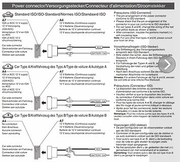
car conforms to ISO standard. For car Types A and B, change the wiring of the red and yellow leads as shown at below. After connection, insulate the portions marked (*). Note: For cars other than A and B, please consult your local car shop. A7 IGN or ACC 12 V supply 12 V-Versorgung IGN/ACC Alimentation
-
Thread
Aufbau Bitmap Hex-file
BMP_H */ /* The .bmp file format Introduction: The .bmp file format (sometimes also saved as .dib) is the standard for a Windows 3.0 or later DIB (device independent bitmap) file. It may use compression (though I never came across a compressed .bmp-file) and is (by itself) not capable of
Microsoft API documentation. Stdvalue stands for standard value. There actually is no such a thing as a standard value but this is the value Paint assigns to the data element if using the bitmap dimensions specified above (100x100x256). The meaning-column gives a short explanation of the purpose of
-
Thread
RISC/V-basierter Router von Shenzhen Xunlong, neue Renesas-MCU, große Politik und mehr
this combination of features makes the RA2L2 the premier solution available for portable devices such as USB data loggers, charge cases, barcode readers and other products. In addition to USB-C with CC detection up to 15W (5V/3A) and USB FS support, the new MCUs offer LP UART, I3C, and CAN interfaces,
Versal™ devices. The latest release also delivers features to maximize FMAX for Versal SSIT devices as well as ease-of-use improvements for all families for IP integration and functional verification. Release Highlights: • Spartan UltraScale+ and Next-Generation Versal Device Support
-
Thread
[V] Verkaufe verschiedene ICs, teilweise DDR
4,15 Euro mit Sendungsnummer bzw. 1,80 Euro auf Risiko des Käufers. 1) 4x CMOS-SRAM 512K x 8 Bit AS6C4008-55 EUR 20,00 2) 2x I2C-Displaytreiber SAA1064 EUR 15,00 3) 5x LED-Zeilen-IC A277 EUR 18,00 4) 3x Audiosteuer-IC TDA1524 EUR 10,00 5) 6x ADC für Messgeräte 3 Digit C520 EUR
-
Thread
Compatibilität von PCIe 4.0/5.0 SSDs zu PCIe 3.0 Noetbook Bus?
backwards compatibility, the Link initially trains to L0 at the 2.5 GT/s data rate using 8b/10b encoding as described in Section 4.2.1, then when the data rate is changed to 8.0 GT/s or higher, 128b/130b encoding is used." Tut es das nicht, darf da nicht PCIe draufstehen. fchk PS: Ich habe mal in
-
 Bild
Datenblatt Ausschnitt Dual Common Cathode Schottky Rectifier
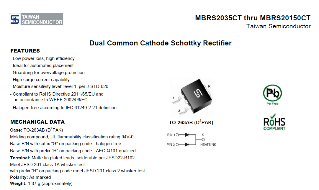
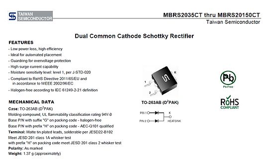
class 1A whisker test with prefix "H" on packing code meet JESD 201 class 2 whisker test Polarity: As marked Weight: 1.37 g (approximately) Pb-Free ROHS COMPLIANT
-
Thread
Paket von der Packstation ohne Internet holen? Gesperrt
genau so gemacht. Nope. Der Händler hat sich beworben. DHL stellt die Automaten nicht selber auf, as in "da würden wir das gerne machen". Jeder Standortinhaber bewirbt sich. Daher gibt es bei uns im Ort trotz >12k Einwohner nur eine Box relativ ungünstig beim Aldi gelegen, wohingegen im <6000EW-Nachbarort
-
Thread
JLCPCB Bahrain-Bahrain-, was ist das?
Our colleague in Germany is closely following > up with it. We will solve this and make delivery as soon > as possible.
-
Thread
wer ist das im SRD Band 868 MHz?
herum. Die blau markierten Übertragungen sind XBee 868MHz Module mit 80kBaud/s und aktivierter AES128-ECB Verschlüsselung (mit key != 0x0000...). Nur so interessehalber: Warum hast du als center frequency für den Mitschnitt genau 866.45 MHz gewählt?
-
Thread
USB Debugging "Unkown Device"
von LeCroy verbaut (vielleicht auch Iwatsu - wer weiß). An meinem MSI B650 Pro4, so wie an einem AsRock P5K Pro und dem ursprünglichen Intel Desktop Board mit Celeron 2GHz aus dem Scope wird das Frontpanel zuverlässig erkannt (VID 0x047, PID 0x0004). Beim Gigabyte jedoch wird der Device-Descriptor
-
Thread
[V] 20St. SILABS 8051 USB-EFM8UB20F64G-B - QFP32 (15€)
communication peripherals. https://www.mouser.de/ProductDetail/Silicon-Labs/EFM8UB20F64G-B-QFP32?qs=OycAS1CGnlj3PApaQXt1oA%3D%3D https://www.silabs.com/mcu/8-bit-microcontrollers/efm8-universal-bee/device.efm8ub20f64g-qfp32?tab=specs 15€ + 1,10€ Kompaktbrief (PS: Sind auch mehr da! Anfrage per