how-to-test-a-transistor-and-a-diode-with-a-multimeter.html Testing Procedure for NPN Transistors Connect the red lead to the base (B) of the transistor. • Connect the black lead to the emitter (E). • Check the reading on the multimeter. Wert bei 760 auf allen Now, check the base-collector junction to see if it’s working correctly. • Keep the red lead on the base (B). • Move the black lead to the collector (C). Wert liegt bei 726 auf allen E(red)-C (black) 260 C(red)-E(black) über geht auf über 2000 schwenkt dann auf 1 Die Widerstände sind an alle Relais
microcontrollers-microprocessors/stm32c5-series.html Im Rahmen der Ankündigung betont man an mehrerlei Stelle die Vorteile der 40nm-Fertigungstechnologie: [c] Während der Arm-Kern fortschrittliche Leistung und Effizienz liefert, ist STs proprietärer 40-nm-Fertigungsprozess kosteneffizient, unterstützt höhere Taktraten und ermöglicht
The RH850/U2C operates with interfaces designed for modern E/E architectures, such as Ethernet 10base-T1S , Ethernet TSN (1Gbps/100Mbps), CAN-XL, and I3C. It also maintains full compatibility with commonly used interfaces today, such as CAN-FD, LIN, UART, CXPI, I²C, I²S, and PSI5. [/c] In der
SYMBOL PARAMETERS CONDITIONS MIN TYP MAX UNIT Raudio_in Audio input impedance At pin ALI and ARI 5 40 k 1 Caudio_in Audio input capacitance At pin ALI and ARI 2 5 pF G audio_In Audio input gain RIN[1:0] = 10 -9 6 dB G audio_In Audio gain step For any gain setting 0.5 1 1.5 dB τ Pre-emphasis time constant
-10 ºC to +55 ºC (de-rating characteristic applies) Option: -30 ºC to +55 ºC Storage temperature -40 ºC to +70 ºC Compliance and safety CE / Option: CHAdeMO Input AC power connection 3P + N + PE Input voltage range 400 V AC+/-10% (50 Hz or 60 Hz) N Max. rated input current & power 125A, 86 kVA F 1 Power
schlecht ist FBAS nicht. Bei Texten verschmiert das auch ziemlich. [[Fehlersuche]] *Test mit BAS Ausgang (Monochrom) direkt am Amiga -> Astreines Bild (d.h. Kabel und TV sind OK) * Ich hab die vier Elkos getauscht, die auf der Platine sind. -> Keine Änderung (hier hatte ich noch keinen Schaltplan
SubD-Connectors eigentlich für ein Takt? Je nach Dokument heißt der C1 oder CCK, der wird von Agnus an Pin 40 erzeugt. > Das vierfache der Farbträgerfrequenz? Sieht wohl so aus, macht bei PAL 4x4,433MHz = 17,732MHz
regulator capable of delivering 10 mA to external circuitry. Osc 17 Oscillator input. A transistor base preseto an external subcarrier input, or is available for in constructing a Colpitts oscillator (see Figure 4). Oscout 18 Oscillator output. The emitter of the transistor, with base access at Pin 17
Distan- (sieheunten). um 2010 herum für die Fahrzeugvernet- zen(sieheTabelle).Sosetztbeispielswei- 100Base-T1 mit PoDL könnte Über - zung entwickelt. In den Kabelbäumen, se1000Base-T1fürseinemaximaleÜber- wachungskameras über bis zu 15 Meter diediesichstetigvermehrendenOnboard- tragungsdistanzvon40Meterningröße
EtherCAT-Protokoll syncen heitskritische Applikationen Kelvin-Kontakten und steuern. Seite 30 entwickeln. Seite 40 verhindern. Seite 80 KOMMUNIKATIONSTECHNIK // PROZESSAUTOMATION o TITELSTORY s k / 10BASE-T1L ist der nächste große Schritt hin zu einer durchgängigen Ethernet-Infra- o struktur – nicht zuletzt in der
getrennt zugeführt. Zur Ansteuerung eines Monitors mit kombiniertem Video- und Synchronisationssignal (BAS-Eingang) müssen die drei Ausgänge BAS, /HSYN und /VSYN zur Erzeugung des BAS-Signals miteinander verbunden werden. Sie sind dazu mit Open-Kollektor-Treibern versehen. Die Pegel können gegebenenfalls
Compatible ecis making it ideally suited for a wide variety of applications. Medium Quality Reference, 40ppm (Typ) on Board The ICL71C03 is an improved CMOS plug-in replacement for Blinking Display Gives Visual Indication of Over Range /2 the lCL7103 and should be used in all new designs. git, Six Auxiliary
00000028 T HAL_SYSTICK_Config 08000387 00000008 T HAL_SYSTICK_IRQHandler 08001b35 00000060 T HAL_TIM_Base_Init 08003225 0000004e T HAL_TIM_Base_MspInit 08001b99 00000002 W HAL_TIMEx_Break2Callback 08001b97 00000002 W HAL_TIMEx_BreakCallback 08001b95 00000002 W HAL_TIMEx_CommutCallback 08001e83 00000004
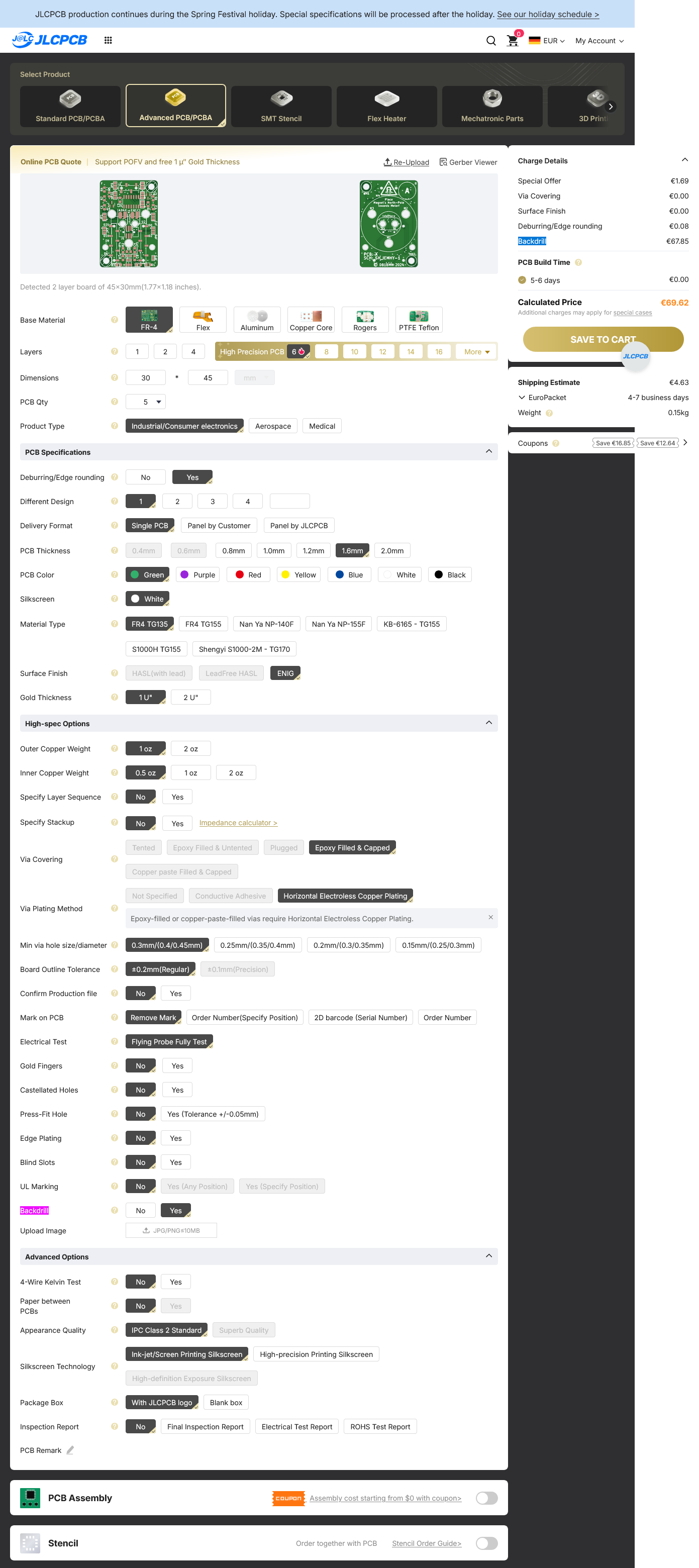
days €0.00 Calculated Price €69.62 Shipping Estimate €4.63 Weight 0.15kg Coupons Save €16.00 Save €12.40 Base Material Dimensions Layers PCB Qty Product Type PCB Specifications Deburring/Edge rounding Different Design Delivery Format Single PCB Panel by Customer Panel by JLCPCB PCB Color Gold Thickness
Capacitance: 23pF requency: 1 M ,5MHz o 10MHz F cy: Hz, 1 r z (utomatic selection) Int al . rnal ime Bas S ti ernal vs. External T e election: Maanual: select Iternaor Extternal Automatic: Internlused when Ex rnal not present (default) Tim Base O utput t Specifi ti ons OutputtFrequency: 10MHz z Voltage
find viele Fehler einfach nicht. Bei den Fotos sind beide Eingänge auf Plus aber irgendwie ist die Base auf Minus geschaltet und ich hab keine Ahnung warum Typischerweise ist dann auf der Rückseite eine Leiterbahn nicht getrennt, das ist hier aber nicht der Fall. Der Ausgang ist auf Minus was mich nur
schrieb im Beitrag #8002680: > Bei den Fotos sind beide Eingänge auf Plus aber irgendwie ist die Base > auf Minus geschaltet und ich hab keine Ahnung warum Oh ha, bei diesem Aufbau kann alles mögliche sein. Es hilft nur messen, an jedem einzelnen Anschluss, also nicht glauben dass alles was
Kanal 3, der andere auf Kanal 11). Ich sehe 12 APs in 2,4 GHz, alle mit 20 MHz Breite, niemand mit 40 MHz. Mittlerweile hübsch verteilt auf 1,6,11. Früher war mal ein Esel dabei, der meinte, zwischen diesen Stühlen sässe es sich besser.
wenn man das Band auf eine kritische Frequenz festgenagelt hat. https://fritz.com/apps/knowledge-base/FRITZ-Box-7590/1349_5-GHz-Funknetz-gelegentlich-deaktiviert-Radar-Signal
IEC (NEMA option) IEC IEC, NEMA Metric Frame 75, 95, 115, 142, 55, 67, 89, 115, 142, 190 mm 2, 3 in 40, 60, 80, 130 mm 190, 250 mm Inertia Med. (high inertia option) Low Low Low, medium Peak Torque Up to 3611 lb-in (408 Nm) Up to 2257 lb-in (255 Nm) Up to 144 lb-in (16.2 Nm) Up to 301 lb-in (34 Nm) Base
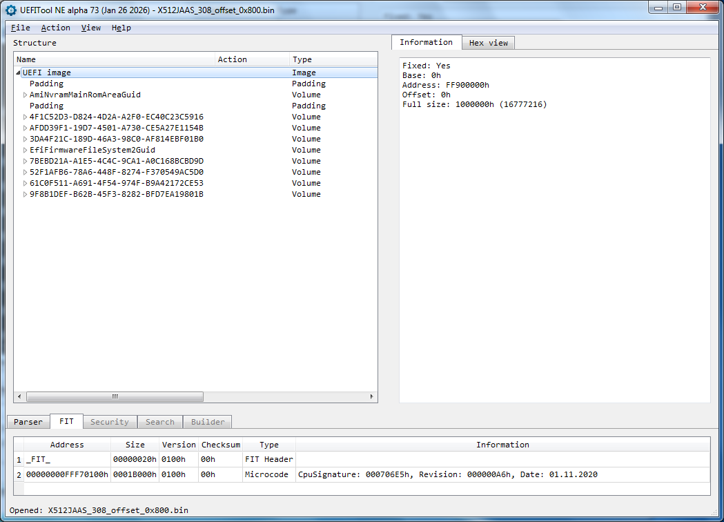
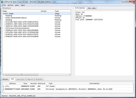
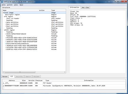
File Action View Help
Structure Information Hex view
Name Action Type
UEFI image Fixed: Yes
Padding Base: 0h
Padding Address: FF900000h
41FC52D3-28D4-A2F0-E40C2C35916 Offset: 0h
Padding Full size: 1000000h (16777216)
...
Parser FIT Security Search Builder
Address Size Version Checksum Type Information
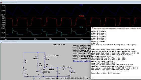
20k-Poti verwenden - gibt es, ist aber eher unüblich. Die 4 Spannungsquellen in Reihe zu den Basen sind nur zu testzwecken (flat(2m) bedeutet, dass bei jedem Simulationslauf die Spannung zufällig gleichverteilt zwischen -2mV und +2mV festgelegt wird) um nachzuvollziehen, wie groß die Abweichungen
Konzepte aus dem Kreuz leiere, > die dann bestenfalls aehnlich gut/schlecht sind, wie die von vor 40..50 > Jahren verwendeten - musses wirklich heutzutage noch analog sein? Mit > irgendeinem popeligen <=8 pin µController kriegt man das doch prima hin, > ohne Temperatur- oder Bauteiltoleranzen,
Voltage (for ULN2002A/D - 2003A/D - 2004A/D) 30 V Ic Continuous Collector Current 500 mA Ib Continuous Base Current 25 mA Tamb Operating Ambient Temperature Range – 20 to 85 ⋅C T stg Storage Temperature Range – 55 to 150 ⋅C Tj Junction Temperature 150 ⋅C THERMAL DATA Symbol Parameter DIP16 SO16 Unit Rth j-amb
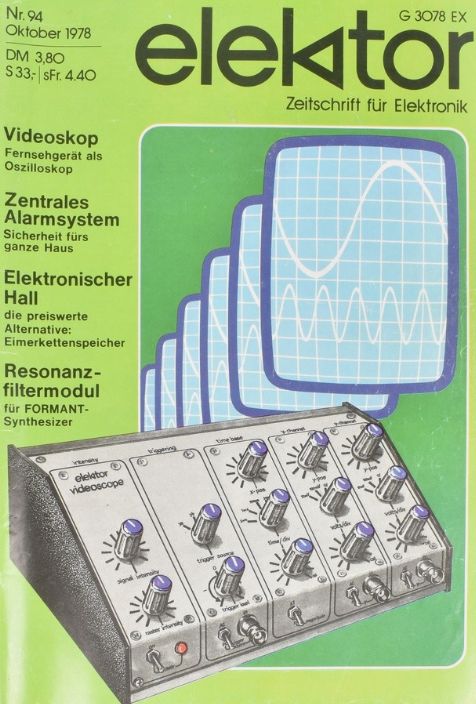
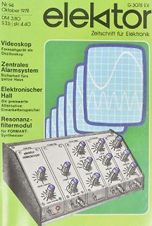
Nr. 94
Oktober 1978
DM 3,80
S 33; sFr. 4,40
elektor
Zeitschrift für Elektronik
Videoskop
Fernsehgerät als Oszilloskop
Zentrales Alarmsystem
Sicherheit fürs ganze Haus
Elektronischer Hall
die preiswerte Alternative: Eimerkettenspeicher
Resonanzfiltermodul
Leuchtstofflampen)? Erstere haben keine Heizung, und können viel, viel dünner hergestellt werden. 30..40 cm Länge und 2 mm Durchmesser sind nichts besonderes. (Wobei ich zugeben muss, nicht recherchiert zu haben, ob es jemals herkömmliche Leuchtstofflampen mit derartigen Dimensionen gab; das dünnste,
Um Fragen vorzubeugen. Die 4.7 sind normale Keramik in 0603. Ist ja kein Audio hier. .-) Und die BAS32 ist deshalb da weil ich da einen mittleren Berg von habe. Vermutlich geht da so ziemlich jede Diode. Also nimm 1N4148 falls du das probieren willt. Vanye
NCV4276B TYPICAL PERFORMANCE CHARACTERISTICS − 4276B Version 5.2 3.45 V I 13.5 V V = 13.5 V V RL= 1 kW V3.40 I ( ( RL= 1 kW G 5.1 G T T3.35 L L V V T 5.0 T3.30 U U T T U U3.25 , , Q 4.9 Q V V3.20 4.8 3.15 −40 0 40 80 120 160 −40 0 40 80 120 160 TJ, JUNCTION TEMPERATURE (°C) TJ, JUNCTION TEMPERATURE (°C) Figure
external filter to transport signals to the media in The DM9161 uses a low power and high performance 100BASE-TX or 10BASE-T Ethernet operation. CMOS process. It contains the entire physical layer 2. Block Diagram 100Base-FX PECL Interface 100Base- TX MII/RMII/ 100Base-TX PCS GPSI Transceiver Interface 10Base-T
Support 1b 1 = 100BASE-TX full duplex is supported by the local device 0 = 100BASE-TX full duplex is not supported 7 TX_HDX RW 100BASE-TX Support 1b 1 = 100BASE-TX half duplex is supported by the local device 0 = 100BASE-TX
Drift ΔV /ΔT −40°C ≤T ≤ +85°C OS A C = 100 µA,VCB 0V 0.4 2 µV/°C BreakdownVoltage BV CEO C = 10 µA 40 V −40°C ≤T A +85°C 40 V Gain-Bandwidth Product fT C = 1 mA,V CE10V 300 MHz Collector Leakage Current Base ICBO VCB
connected. Transistor Measurement(2SA1941): Display the Collector cutoff current Iceo with currentless base (10uA units) and Collector residual current Ices with base hold to emitter level . This values are only shown, if they are not zero (especially for Germanium transistors). Thyristor Measurement(MCR100
Beitrag #7988343: > Nummer 3 ist dann die YIHUA 982. > Die wirkt optisch etwas billig und hat nur 40 Watt, was für meine > Bedürfnisse eventuell zu wenig sein könnte. 200W, 180W, 40W? Die C210-Lötspitzen leisten bei Betriebsspannung 40W, die C245-Lötspitzen leisten 110W. Die Yihua 982 hat bei
aus Barcelona haben, aber Du verdingst Dich ja auch nicht als Lohnbestücker, bei dem der Lötkolben 40 Stunden in der Woche gefordert ist.
AMPERE DARLINGTON ÎÎÎÎÎCollector–Emitter Voltage V 60 ÎÎ80 Vdc CEO POWER TRANSISTORS ÎÎÎÎÎCollector–Base Voltage V 60 ÎÎ80 Vdc COMPLEMENTARY CB ÎÎÎÎÎEmitter–Base Voltage V 5.0 ÎÎÎ Vdc SILICON EB 60–80 VOLTS ÎÎÎÎÎCollector Current ÎÎ I 10 Adc C 150 WATTS ÎÎÎÎÎBase CurrentÎÎÎÎÎ ÎÎ I 0.2 Adc B ÎÎÎÎÎTotal
non-operating) Relative humidity gradient (max) 30% per hour Wet bulb temperature 37.7°C max (operating) 40.0°C max (non-operating) Altitude, operating –304.8 m to 3048 m (–1000 ft to 10,000+ ft) Altitude, non-operating –304.8 m to 12,192 m (–1000 ft to 40,000+ ft) (below mean sea level, max) Seagate BarraCuda
Settings (driven input = +8 dBu on +8 dBu input range) CH A into CH B 70 Hz to 5 kHz ≥85 dB >5 kHz to 40 kHz ≥75 dB >40 kHz to 80 kHz ≥65 dB CH B into CH A 70 Hz to 5 kHz ≥85 dB >5 kHz to 40 kHz ≥80 dB >40 kHz to 80 kHz ≥70 dB (typically ≥85 dB) Undriven Channel Set to Autorange (driven input = +8 dBu on +8 dBu input range) CH A into CH B 70 Hz to 5 kHz ≥115 dB >5 kHz to 40 kHz ≥105 dB >40 kHz to 80 kHz ≥ 95 dB CH B into CH A 70 Hz to 5 kHz ≥112 dB >5 kHz to 40 kHz ≥110 dB >40 kHz to 80 kHz ≥108 dB 1–6 AM700 Audio Measurement Set Service Manual Specifications Table 1–2:
Level-1-260C-UNLIM -40 to 125 PS63021 TPS63021DSJR.B Active Production VSON (DSJ) | 14 3000 | LARGE T&R Yes NIPDAU Level-1-260C-UNLIM -40 to 125 PS63021 TPS63021DSJRG4 Active Production VSON (DSJ) | 14 3000 | LARGE T&R Yes
#7985673: > aber das klappt irgendwie nicht... Adresse ist falsch eingegeben (0x04... Statt 0x40...). Die CPU ist nicht angehalten? Klingt als wäre es bereits abgestürzt/neugestartet? Passiert das so auch wenn du nur dein Programm "normal" geflasht hast, und genau so direkt im Reset_Habdler angehalten
Transistor der diese Spannung schaltet, habe ich auf der Platine identifiziert, die Spannung an der Base fällt mit der originalen Firmware auf 4,3V, bei mir bleibt sie auf 5V :-( Hat noch jemand einen Tipp, was ich noch probieren könnte?! Die Original-Firmware ist hier zu finden: https://github.com
Single Channel LED Backlight Driver 1 Features 3 Description • 2.7-V to 5.5-V input voltage With a 40-V rated integrated switch FET, the • Integrated 40-V, 1.8-A MOSFET TPS92360 is a boost converter that drives LEDs in • Drives LED string up to 38 V series. The boost converter has a 40-V, 1.8-A internal

 Bild

 Bild
 Bild
 Bild
 Bild
 Bild