-
Datei
PICO-RX_1_.html
Spektrum- und Wasserfallanzeige </b></big><big><b>vorgeschlagenes </b><b>externes 2.4" OLED-Dispay ( ILI9341 ) anschliessen lässt.<br> </b></big><br> <hr width="100%" size="2"><big><b>Es folgen Angaben zu den von mir verwendeten etwas spezielleren Bauteilen und ggf. Angaben zu möglichen Bezugsquellen
-
Datei
meindef.h
); // if(temp.btf.bit6 == 1) temp1.btf[3].bit5 = 1; // return temp1.w; // Für 16 bit Farbe (so wie ILI9341) typedef struct{ u8 farbeB:5; // Farbe blau, bit 4:0 u8 farbeG:6; // Farbe grün, bit 10:5 u8 farbeR:5; // Farbe rot, bit 15:11 } bitfarbe565; typedef union{ u16 h ; // Farbe 16bit bitfarbe565 frb
in „I2C Display einfache Frage“ · Mikrocontroller und Digitale Elektronik ·
-
Datei
meindef.h
); // if(temp.btf.bit6 == 1) temp1.btf[3].bit5 = 1; // return temp1.w; // Für 16 bit Farbe (so wie ILI9341) typedef struct{ u8 farbeB:5; // Farbe blau, bit 4:0 u8 farbeG:6; // Farbe grün, bit 10:5 u8 farbeR:5; // Farbe rot, bit 15:11 } bitfarbe565; typedef union{ u16 h ; // Farbe 16bit bitfarbe565 frb
in „AVR-Studio 4.19 und JTAG ICE MK2 unter Windows 11 64 Bit installieren“ · Mikrocontroller und Digitale Elektronik ·
-
Datei
mmc_stm32f1.c
64; SPI_InitStruct.SPI_FirstBit = SPI_FirstBit_MSB; SPI_Init(SPI1, &SPI_InitStruct); /* SPI für LCD ILI9341 einschalten */ SPI_Cmd(SPI1, ENABLE); } /* Exchange a byte */ static uint8_t xchg_spi (uint8_t dat) /* Data to send */ { while (SPI_I2S_GetFlagStatus(SPI1, SPI_I2S_FLAG_TXE) == RESET); /* Wait for
in „STM32Fxxx: Frage zur Initialisierung mit der StdPeriphLib“ · Mikrocontroller und Digitale Elektronik ·
-
Datei
lcd_init.c
SPI_InitStruct.SPI_FirstBit = SPI_FirstBit_MSB; SPI_Init(LCD_SPI, &SPI_InitStruct); /* SPI für LCD ILI9341 einschalten */ SPI_Cmd(LCD_SPI, ENABLE); f_spi_initialized = true; } /* --------- Wechselt auf den 16 Bit Mode -------- */ void LCD_SPI_16Bit() { /* SPI abschalten */ SPI_Cmd(LCD_SPI, DISABLE);
in „Lebensdauer von lokalen Variablen“ · Softwareentwicklung ·
-
Datei
compile_Tasmota_stable_in_docker_container.txt
build/tasmota32-DE/lib40a/FrogmoreScd40/FrogmoreScd40.cpp.o Compiling .pio/build/tasmota32-DE/libde0/ILI9341-gemu-1.0/ILI9341_2.cpp.o Compiling .pio/build/tasmota32-DE/lib351/IRremoteESP8266/IRac.cpp.o Compiling .pio/build/tasmota32-DE/lib351/IRremoteESP8266/IRrecv.cpp.o Compiling .pio/build/tasmota32-
in „Dlock 11827 und Tasmota - compilieren für FW-Update“ · Haus & Smart Home ·
-
Datei
Configuration.h
define TFT_GENERIC #if ENABLED(TFT_GENERIC) // :[ 'AUTO', 'ST7735', 'ST7789', 'ST7796', 'R61505', 'ILI9328', 'ILI9341', 'ILI9488' ] #define TFT_DRIVER AUTO // Interface. Enable one of the following options: //#define TFT_INTERFACE_FSMC //#define TFT_INTERFACE_SPI // TFT Resolution. Enable one of the
in „Ender3 Z-Achse fährt mit Marlin nur nach oben“ · Mechanik, Gehäuse, Werkzeug ·
-
 Bild
Bild
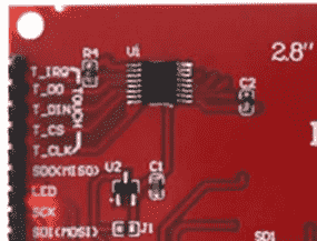
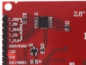
Ausschnitt einer roten Leiterplatte
T_IRQ R1 U1 2.8" C2 T_CS T_CLK SDX(MISO) U2 C1 LED SCK SDI(MOSI) J1 SD1
in „Hilfe 2.8" LCD Problem“ · Mikrocontroller und Digitale Elektronik · · Platinenfotos
-
Datei
Configuration.h
define TFT_GENERIC #if ENABLED(TFT_GENERIC) // :[ 'AUTO', 'ST7735', 'ST7789', 'ST7796', 'R61505', 'ILI9328', 'ILI9341', 'ILI9488' ] #define TFT_DRIVER AUTO // Interface. Enable one of the following options: //#define TFT_INTERFACE_FSMC //#define TFT_INTERFACE_SPI // TFT Resolution. Enable one of the
in „Custom 3D-Drucker zu ausgebuchtete Ecken“ · Mechanik, Gehäuse, Werkzeug ·
-
PDF
STM32Cube-MX-HAL-MOOC-presentation-16-9.pdf
Discovery drivers stm32f4xx_discovery.c stm32f4xx_discovery_sdram.c stm32f4xx_discovery_io.c Components ili9341.c lis3dsh.c stmpe811.c HALAPI stm32f4xx_hal_spi.c stm32f4xx_II_fmc.c stm32f4xx_hal_sdram.c stm32f4xx_hal.c stm32f4xx_hal_i2c.c Examples with BSP 267 • How to import BSP into your project • How use
in „STM32 HAL Tutorial“ · Mikrocontroller und Digitale Elektronik ·
-
PDF
handy_lcd_schaltplan.pdf
Diagram S5360 Block Diagram 2M FF SF LCD: 320* 240,(2.98”) SENSOR QVGA TN TFT(BOE Panel) Earphone ILI9341 - LDI (3.5 phi) DC Motor C- type TSP Receiver (9phi, 3.4T) Speaker (1115, 3.5T) PMU(MAX8986) GPS 3 DCDC BCM4751 BCM21552 / B0 18 LDOs (11X11 464 pin FBGA) WI-FI/BT/FM BCM4330 GSM/GPRS/EDGE Battery
in „Altes Handy Display zum Basteln“ · Mikrocontroller und Digitale Elektronik ·
-
Datei
newSDWebServer_GPIO16_Touchn5b.ino
BRIGHT_BLUE ; char str_buf1[25] ; char str_buf2[50] = {"WELCOME TO THE ESP07 BOARD ==> DEMO "} ; #define ILI9341_TFTWIDTH 320 #define ILI9341_TFTHEIGHT 240 //#define RGB565CONVERT(red, green, blue) (int) (((red >> 3) << 11) | ((green >> 2) << 5) | (blue >> 3)) char X,Y ; char num1,num2,num3 ; // Variable for
in „Arduino_IDE mit ESP8266 und Ucglib unter Win7-64bit“ · Mikrocontroller und Digitale Elektronik ·
-
PDF
kicad_8450_dcm_liste_neu_v3.pdf
cathode SMD mount HY1602E LCD 16x2 Alphanumeric 16pin Blue/Yellow/Green Backlight, 8bit parallel, 5V VDD ILI9341_LCD_Breakout ILI9341 controller, SPI TFT LCD Display, 9-pin breakout PCB, 4-pin SD card interface, 5V/3.3V KCSA02-105 One digit 7 segment hyper red LED, common anode KCSA02-106 One digit 7 segment
in „KiCAD Eeschema, Bibliotheksdokumentation *.dcm als PDF-Datei“ · Platinen ·