-
Datei
dds-seq.asm
0x6d,0x70,0x74,0x77,0x7a,0x7d TRIANGLETABLE: ; Seite 3 - Dreieck .db 0x00,0x02,0x04,0x06,0x08,0x0a,0x0c,0x0e .db 0x10,0x12,0x14,0x16,0x18,0x1a,0x1c,0x1e .db 0x20,0x22,0x24,0x26,0x28,0x2a,0x2c,0x2e .db 0x30,0x32,0x34,0x36,0x38,0x3a,0x3c,0x3e .db 0x40,0x42,0x44,0x46,0x48,0x4a,0x4c,0x4e .db 0x50,0x52,0x54,0x56,0x58,0x5a
in „Claude Code trifft AVR-Assembler: vom Chip in den Browser mit einem Prompt“ · Entwickeln mit KI ·
-
PDF
CAN_uC_V2_CPU_27Aug2011.pdf
Sc VCC 8 4 Y GND 3 A2 SCL Rc Sd VCC 3 6 2 7 IC1 4 VSS SDA 5 3 Tc Rd 6 4 GND Td 5 NC7S08M5 GND 4 R p GND-Insel p TWI EEPROM N 0 2 2 ODER R 1 2 Q1 2 FM24V10 FRAM 4 3 2 1 4 3 2 1 4 3 2 1 1 32,768KHz 1 GND GND 3 GND 3 C 1 VDD P82B96 und Pico-Gate AND 1 2 C DQ IC4 zum Entkoppeln von SPI und TWI
in „Anforderungssammlung CAN Hausbus mit PIC µC“ · Haus & Smart Home ·
-
PDF
CD00161566.pdf
code with data processing running from RAM (1) Max Symbol Parameter Conditions fHCLK Unit TA= 85 °C TA= 105 °C 72 MHz 48 50 48 MHz 31.5 32 External clock , all36 MHz 24 25.5 peripherals enabled 24 MHz 17.5 18 16 MHz 12.5 13 Supply 8 MHz 7.5 8 I current in mA DD 72 MHz 29 29.5 Run mode 48 MHz 20.5 21
in „[F] STM32F103: Lastkondensatoren“ · Mikrocontroller und Digitale Elektronik ·
-
PDF
Produktdatenblatt__4114_N_2H4P.pdf
= 200mA/div ; t = 1s/div) 10.05.2017 Seite 7 von 12 Produktdatenblatt 4114 N/2H4P Anlaufstrom @ 24 V (I = 500mA/div ; t = 2s/div) Laufstrom @ 24 V (I = 500mA/div ; t = 1ms/div) Interne Sicherung: Littelfuse
in „Ansteuerung / Strombegrenzung PWM Lüfter“ · Analoge Elektronik und Schaltungstechnik ·
-
PDF
Preview_of__io.h_.pdf
io.h 24.07.12 15:37 /* Copyright (c) 2002,2003,2005,2006,2007 Marek Michalkiewicz, Joerg Wunsch Copyright (c) 2007 Eric B. Weddington All rights reserved. Redistribution and use in source and binary forms, with
in „µC am Mac mit C programmieren“ · Mikrocontroller und Digitale Elektronik ·
-
PDF
TSynth_Schematic_V1_1.pdf
3 1 3 1 C V I0 9 C4 2 2 2 2 2 2 2 2 8 C5 I1 MUX1_Com 1 COM I2 7 C6 6 C7 I3 GND 1 GND U2 I4 5 C8 2 CD74HC4067M 4 C9 2 & 3 cannot be used 0_RX1_MOSI1_TOUCH I5 #U5 duplicated with 26, 27 3 1_TX1_MISO1_TOUCH MUX_Addr_S0
in „Electrotechnic T-Synth DIY Synthesizer - Platinenanalyse“ · Mikrocontroller und Digitale Elektronik ·
-
PDF
FINDER_30.22.7.012.pdf
Dual-In-Line-Relais 1,25 A 30 30.22.7 30.22.9 - Kleine Bauform - Leiterplatten - Relais - Sensitive DC-Spule, 200 mW - Für kleine Schaltlasten - Schutzart: IP 67 - Spule sensitiv, 200 mW - Spule, 400 mW - Für Leiterplatte/Dual-in-line Für Leiterplatte/Dual-in-line 1214 22 24 1214 22 24 A1 111214 A1 111214 20.3 10.1
in „5V Mikrocontroller an 12V Kartenrelais“ · Mikrocontroller und Digitale Elektronik ·
-
PDF
AD694AR.pdf
40.0 50.0 40.0 50.0 M Current Limit (@ 2 × FS Overdrive 24 44 24 44 mA Slew Rate 1.3 1.3 mA/ s SPAN AND ZERO ACCURACY 1 2 4 mA Offset Error @ 0 V Input Error from 4.000 mA, 4 mA On ±10 620 ±5 610 A Error from 0.000 mA, 4
in „4-20mA für Durchlussregler erzeugen - AD694“ · Mikrocontroller und Digitale Elektronik ·
-
PDF
Aceton_v020.pdf
entzündlich, wirkt aber nicht brandfördernd (oxi- dierend). untere Explosionsgrenze: 2,50 % (V); 57 g/m³ obere Explosionsgrenze: 14,30 % (V) ; 290 g/m³ Dampfdruck: 240 hPa bei 20 °C 800 hPa bei 50 °C Relative Gasdichte: 2,1 (trockene Luft = 1) Dichte: 0,79 g/cm³ bei 20 °C Löslichkeit(en): bei 20 °C: in
in „Brennbare Lösungsmittel im Ultraschallreiniger“ · Offtopic ·
-
PDF
DDZ97xx.pdf
Diodes Incorporated DDZ9689S - DDZ9717S 100m 10m A T 1m N E R U C E N Z Z I 100n 10n 0 5 10 15 20 25 30 35 40 45 100m 100m 10m 10m ) ) ( ( 1m T 1m N E E R R R U C C R R E N E E Z , I I 100n 100n 3.0 4.0 5.0 6.0 7.0 8.0 9.0 8.0 10.0 11.0 12.0 13.0
in „Komparator für 24V LOW BAT“ · Analoge Elektronik und Schaltungstechnik ·
-
PDF
DS-00129-GD25Q41B-Rev2.0.pdf
..........33 7.23. READ M ANUFACTURE ID/DEVICEIDD UALI/O(92H) .................................................................................................34 7.24. READ M ANUFACTURE ID/DEVICEIDQ UAD I/O(94H)..............
in „ESP8266-07 Reset Loop“ · Mikrocontroller und Digitale Elektronik ·
-
Datei
OutputSynthesis.txt
to wire fifodout @W: CG360 :"C:\Users\wagnersn\Desktop\VerilogRamTest\RamTest\main - Kopie.v":20:6:20:13|No assignment to wire fifowclk At c_ver Exit (Real Time elapsed 0h:00m:00s; CPU Time elapsed 0h:00m:00s; Memory used current:
in „If-Bedingung nach dem Einschalten, falsch initialisiert?“ · FPGA, VHDL & Co. ·
-
PDF
111COMX_Communication_Module_DG_16_EN.pdf
COMX 10 at start-up: At start-up: Host mode selection LVTTL Input 24 Read, active low IOU6 IOU9 IO18C DPM_RDn LVTTL Input 25 Write, active low IOU6 IOU9 IO18C DPM_WRn LVTTL Input 26 Chip select, active loIOU6 IOU9 IO18C DPM_CSn LVTTL Input Table 18: COMX Pinning of the
in „Externes SRAM + Atmel AT91SAM7SE“ · Mikrocontroller und Digitale Elektronik ·
-
PDF
EC_60.pdf
EC 60 ∅60 mm, bürstenlos, 400 Watt, approved r o t o m C E n o x a m M 1:4 Lagerprogramm Bestellnummern Standardprogramm Sonderprogramm (auf Anfrage) 167132 167131 Motordaten Werte bei Nennspannung 1 Nennspannung V 48.0 48.0 2 Leerlaufdrehzahl min -1 5370
in „Netzeil für Servoverstärker und Motor“ · Mikrocontroller und Digitale Elektronik ·
-
PDF
VAR-6ULCustomBoard-Datasheet.pdf
. Please pay attention that part of pins is used on SoM so they are useful only on specific subsets of the SoM. 2.3.9.1 I2C, CAN and GPIO Connector Pin- out (J12) Pin# VAR-6ULCustomBoard Signal Type Description 1 I2C2_SCL O I2C Bus 2 Clock 2 GPIO5_5 IO GPIO5
in „[V] Variscite DART-6UL Development Kit inkl. 7" LCD NXP iMX6UL“ · Markt ·
-
PDF
STA310AN.PDF
an.fm STA310 Getting Started analog part Filter (external) ClkIn DIV N+1 Charge Ip (27MHz) PFD Pump R C3 C pll_disable DIV M+1 VCO Uvco dN Switching DIV X+1 Frac Circuit (N.B. when x=1 it divides by 4) update_frac Figure 2: Oclk The equation implemented by the PLL is the following : 1 Oclk = -nputFre-
in „Sammelbestellung STA310 Dolby Digital Decoder“ · Markt ·
-
PDF
CD00187074.pdf
Gain vs output power 70 18 65 860MHz 17 860MHz 60 910MHz 910MHz 960MHz 960MHz 55 16 ] % y 50 B n [ c a 15 f 45 G E 40 Vcc = 3 V 14 Vcc = 2 V Icq = 30mA 35 Icq = 30mA 13 30 25 12 21 22 23 24 25 26 27 28 16 17 18 19 20 21 22 23 24 Output Power [dBm] Output Power [dBm] Figure 16. Efficiency vs output power 70 65 860MHz 60 910MHz 960MHz 55 ] [ 50 c i f 45 E 40 35 Vcc = 2 V Icq = 30mA 30 25 16 17 18 19 20 21 22 23 24 Output Power [dBm] Doc ID 14496 Rev 4 9/18 Test circuit, part list and photo START499D 5 Test circuit, part list and photo Figure
in „Leistungsanpassung bei bipolar Transistoren?“ · Analoge Elektronik und Schaltungstechnik ·
-
PDF
100_inch_DIP_Sockets.pdf
Voltage: 1000 Vrms at Sea Level Environmental Operating Temperature Rating: - 55∞C to +150∞C Mechanical When used as a test socket at room temperature 24∞C the socket will last 20,000 actuations. 3M Electronic Handling and Protection Division 6801 River Place Blvd. For technical, sales or ordering information call 800-328-0411 Austin, TX 78726-9000 or visit our website: http://www.3M.com/ehpd .100"(2.54 mm) DIP Sockets ZIP DIP A F .09 ▯▯1 [ 2.3 ] D .325 [ 8.26 ]▯▯2 T X 2XX-XXXX-00 O C B O 3 M ▯ 3 .100 Typ. [ 2.54 ] .46 [ 11.6 ] Closed .47 [ 11.9 ] .48 [ 12.3 ] .020 .012 X .030 [
in „Suche Textool-Sockel 28pol. Klemmbreite 7.62mm“ · Mikrocontroller und Digitale Elektronik ·
-
Datei
MIDI_D_mpfung_Timeout_V101.bas
sbiC pind,3 ' Trigger 1 erfolgt RJmp S2_l1 ' 29092007 ldi r24,&H80 sts OCR1AH, r24 ' Zählergrenzwert auf Timeoutwert setzen lang ldi r24,0 sts OCR1AL, r24 Out Tcnt1h , R24 ' Zähler rücksetzen Out Tcnt1l ,
in „Problem mit AVR OCA Interrupt“ · Mikrocontroller und Digitale Elektronik ·
-
PDF
ATS2503.pdf
PU2.5k I2C serial clock 40 7mA I2S_MCLK O / I2S clock ICEDI I / Data input of DSU Bit2 of General GPIO_C2 O Z purpose I/O port C 41 UART_RX I 7mA / UART RX I2S_LR O I2S LR SPDIF_RX I / SPDIF RX GPIO_C1 BI Z Bit1
in „Hilfe gesucht zum IC "ATS2503"“ · Mikrocontroller und Digitale Elektronik ·
-
PDF
ST7036-V1.4.pdf
15 16 01 02 03 04 05 06 .......0E 0F 00 For Shift Left 11 12 13 14 15 16 .......1E 1F 10 21 22 23 24 25 26 .......2E 2F 20 1 2 3 4 5 6 14 15 16 0F 00 01 02 03 04 .......0C 0D 0E For Shift Right 1F 10 11 12 13 14 .......1C 1D 1E 2F 20 21 22 23 24 .......2C 2D 2E Fig. 12 3-Line Display V1.4 19/70 2004
in „EA DOG-M Display (ST7046) und customchars. ARGH!“ · Mikrocontroller und Digitale Elektronik ·
-
PDF
doc4368.pdf
. 2 2 m i n T i = = - - 4 r r e n r a C C E 2 e t i i i i i D D r 0 I ' ' G o t r a a a r r % % M M M M M M M M D L L G = . E E A m o H c e e er C C 8 8 S S S S S S S S S O O E 1 I M M m H 4 2 6 a C C C % %
in „Entwicklungsboard für AT89C51 Controllers“ · Mikrocontroller und Digitale Elektronik ·
-
PDF
AKKU1A1.pdf
V anzuheben (4 mV * 6 Zellen * 35°C = 840 mV = 0,84 V). Bei 30°C ist die Ladeschlussspannung beim 12 V Akku um 0,12 V zu senken (4 mV * 6 Zellen * 5°C = 120 mV = 0,12 V). Werden die Akkus nur bei der vom Hersteller festgelegten
in „Erfahrung mit Desulfatisierung von Bleiakkus“ · Analoge Elektronik und Schaltungstechnik ·
-
PDF
Blei_AKKU1A1.pdf
V anzuheben (4 mV * 6 Zellen * 35°C = 840 mV = 0,84 V). Bei 30°C ist die Ladeschlussspannung beim 12 V Akku um 0,12 V zu senken (4 mV * 6 Zellen * 5°C = 120 mV = 0,12 V). Werden die Akkus nur bei der vom Hersteller festgelegten
in „Akku-Technologien: Was ist richtig?“ · Analoge Elektronik und Schaltungstechnik ·
-
PDF
irl2203n.pdf
or M3 srew 10 lbf•in (1.1N•m) Thermal Resistance Parameter Typ. Max. Units RθJC Junction-to-Case ––– 0.85 RθCS Case-to-Sink, Flat, Greased Surface 0.50 ––– °C/W RθJA Junction-to-Ambient ––– 62 www.irf.com
in „Saito Pro Charger Batterieladegerät - Mikrocontroller ATmel ATTINY26L defekt?“ · Mikrocontroller und Digitale Elektronik ·
-
PDF
elv.pdf
, M3 x 5 mm 15 nF/SMD/0805 C26 8 Innensechskant-Schrauben, M3 x 5 mm 22 nF/SMD/0805 C26 6 Senkkopfschrauben, M3 x 6 mm 100 nF/SMD/0805 C1, C4, C5, C8, C20, C21, C24, C25, C32, C36–C40, 5 Zylinderkopfschrauben, selbstschneidend, M3 x 6 mm C44–C48, C50, C53 2 Zylinderkopfschrauben, M3 x 8 mm 100 nF/ker C9–C13, C28 4 Zylinderkopfschrauben, M3 x 16 mm 270 nF/100 V C49 4 Innensechskant-Schrauben, M3 x 16 mm 470 nF/ker C30 4 Muttern
in „Problem mit ELV Netzteil Bausatz PPS 5630“ · Mikrocontroller und Digitale Elektronik ·
-
PDF
ICM7216.pdf
3. ICM7216A TYPICAL I DIG vs VDD -VOUT 30 80 o 4.5 ≤ DD≤ 6V -20 C TA= 25 C V = 5.5V o DD 25 C 60 V DD= 5V 20 ) 85 C ) V = 4.5V m m DD ( ( 40 E E I IS 10 20 00 1 2 3 0 0 1 2 3 VDD-VOUT (V) V (V) OUT FIGURE 4. ICM7216B AND ICM7216D TYPICAL I SEG vs VDD OUT FIGURE 5.
in „[V] 1St. Harris ICM7216AIJI Ceramic DIP28 8-Digit, Multi-Function, Frequency Counters/Timers“ · Markt ·
-
Datei
8080int-jmp.asm
,0x28 .db 0x24,0x20,0x20,0x24,0x20,0x24,0x24,0x20 .db 0x28,0x2c,0x2c,0x28,0x2c,0x28,0x28,0x2c .db 0x00,0x04,0x04,0x00,0x04,0x00,0x00,0x04 .db 0x0c,0x08,0x08,0x0c,0x08,0x0c,0x0c,0x08 .db 0x04,0x00,0x00,0x04,0x00,0x04,0x04,0x00 .db 0x08,0x0c,0x0c,0x08,0x0c,0x08,0x08,0x0c .db 0x24,0x20,0x20,0x24,0x20,0x24,0x24,0x20 .db 0x28,0x2c,0x2c,0x28,0x2c,0x28,0x28,0x2c .db 0x20,0x24,0x24,0x20,0x24,0x20,0x20,0x24 .db 0x2c,0x28,0x28,0x2c,0x28,0x2c,0x2c
in „CP/M auf ATmega88“ · Mikrocontroller und Digitale Elektronik ·
-
PDF
TechNotes_V3.1_Mini-ITX_D3003-S.pdf
" NEC NL6448BC33-63D 640 x 480 NEC 104PW201 12.1" AUO G121SN01-V0 800 x 600 Green-C&C GH093A-ROHS 12.1" LG-Philips LB121S03-TL01 800 x 600 Green-C&C GH001HB-ROHS 15" Sharp LQ150X1LW71N 1024 x 768 TDK CXA-0349 15" AUO G150XG01V0 1024 x 768 Green-C&C GH001A-ROHS 17" AUO M170EG01-VD 1280
-
PDF
datasheet.pdf
24mA source-sink capability Output Low Voltage V OL 0.4 V IOL = 24 mA Output High Voltage V OH 2.4 V IOH = -24 mA Publication Release Date: Aug, 22, 2007 -220- Version 1.4 W83627DHG DC CHARACTERISTICS,
in „(Windows/Winbond) CPU Temperatur auslesen“ · Mikrocontroller und Digitale Elektronik ·
-
PDF
74hct595.pdf
GND current − ±70 mA CC GND CC Tstg storage temperature −65 +150 °C Ptot power dissipation Tamb = −40 to +125 °C; note 1 − 500 mW Note 1. For DIP16 packages: above 70 °C derate linearly with 12 mW/K. For SO16 packages: above 70 °C derate linearly with 8 mW/K. For SSOP16 packages: above 60 °C derate linearly with 5.5 mW/K. For TSSOP16 packages: above 60 °C derate linearly with 5.5 mW/K. For DHVQFN16 packages: above 60 °C derate
in „74HC595 wie steuert man das latch an?“ · Mikrocontroller und Digitale Elektronik ·
-
PDF
74HC595_Philips.pdf
GND current − ±70 mA CC GND CC Tstg storage temperature −65 +150 °C Ptot power dissipation Tamb = −40 to +125 °C; note 1 − 500 mW Note 1. For DIP16 packages: above 70 °C derate linearly with 12 mW/K. For SO16 packages: above 70 °C derate linearly with 8 mW/K. For SSOP16 packages: above 60 °C derate linearly with 5.5 mW/K. For TSSOP16 packages: above 60 °C derate linearly with 5.5 mW/K. For DHVQFN16 packages: above 60 °C derate
in „Definierter Einschaltzustand beim 74HC595“ · Mikrocontroller und Digitale Elektronik ·
-
PDF
74HC595_Shiftregister.pdf
GND current − ±70 mA CC GND CC Tstg storage temperature −65 +150 °C Ptot power dissipation Tamb = −40 to +125 °C; note 1 − 500 mW Note 1. For DIP16 packages: above 70 °C derate linearly with 12 mW/K. For SO16 packages: above 70 °C derate linearly with 8 mW/K. For SSOP16 packages: above 60 °C derate linearly with 5.5 mW/K. For TSSOP16 packages: above 60 °C derate linearly with 5.5 mW/K. For DHVQFN16 packages: above 60 °C derate
in „Unterschied 74HCT595, 74HC595“ · Mikrocontroller und Digitale Elektronik ·
-
PDF
74HC_HCT595.pdf
GND current − ±70 mA CC GND CC Tstg storage temperature −65 +150 °C Ptot power dissipation Tamb = −40 to +125 °C; note 1 − 500 mW Note 1. For DIP16 packages: above 70 °C derate linearly with 12 mW/K. For SO16 packages: above 70 °C derate linearly with 8 mW/K. For SSOP16 packages: above 60 °C derate linearly with 5.5 mW/K. For TSSOP16 packages: above 60 °C derate linearly with 5.5 mW/K. For DHVQFN16 packages: above 60 °C derate
in „74HC595 und ATtiny13 Lauflicht“ · Mikrocontroller und Digitale Elektronik ·
-
PDF
3642fc.pdf
VIN VIN SW VOUT ISET pinshouldbeleftopeninthisexampletoselectmaxi- LTC3642 R1 mum peak current (115mA). Figure 9 shows a complete 5 RUN VFB 6 COUT 7 schematic for this design example. CIN 4 HYST 3 SS SET R2 C GND R V 100µH VOUT SS 8, 9 SET 24VN VIN SW 3.3V 3642 F10a 2M LTC3642 50mA 1µF RUN ISET 10µF
in „Bauteil LDYM N188 817“ · Analoge Elektronik und Schaltungstechnik ·
-
PDF
Traco_Power__TMV_2-2403SHI.pdf
-2403SHI 3.3 VDC 500 mA 76 % TMV 2-2405SHI 5 VDC 400 mA 77 % TMV 2-2409SHI 9 VDC 222 mA 81 % TMV 2-2412SHI 12 VDC 168 mA 82 % TMV 2-2415SHI 21.6 - 26.4 VDC 15 VDC 132 mA 82 % TMV 2-2405DHI (24 VDC nom.) +5 VDC 200 mA –5 VDC
in „isol. DC/DC-Wandler 3,3V geregelt“ · Analoge Elektronik und Schaltungstechnik ·
-
PDF
attiny84.pdf
85 ˚C 0.5 25 ˚C )0.4 ( -40 ˚C O V0.3 0.2 0.1 0 0 5 10 15 20 25 OL(mA) 196 ATtiny24/44/84 8006H–AVR–10/09 ATtiny24/44/84 Figure 21-22. I/O Pin Output Voltage vs. Source Current (V = 3V) CC I/O PIN OUTPUT VOLTAGE
in „Attiny 84 ISP?!“ · Mikrocontroller und Digitale Elektronik ·
-
PDF
HLG-120H-spec.pdf
Driver HLG-120H series IS1THOMAS SAMUELL13) egelma getruft ID 2000000000 (except forAB,D-type) (for 12B,24B,Type HLonly) 110 M M SELV IP65 IP67 ■ Features ■ Applications Constant Voltage + Constant Current mode output LED street lighting Metal housing with class Idesign LED high-bay lighting Built-in active
in „Netzteil für Getriebemotor“ · Analoge Elektronik und Schaltungstechnik ·
-
PDF
AdvancedUseAVRASM2_de_20171104.pdf
einem Makro bekannt sind Wenn man das Konzept der lokalen Funktionen auf lokale Variablen (die man in C "static" nennt) aus- dehnen will, so stößt man auf eine Schwierigkeit: .macro MtestNew .dseg myPrivateVar: .byte 1 .cseg lds R24, myPrivateVar .endm ; MtestNew MtestNew AVRASM2 gibt eine Fehlermeldung
in „Advanced Use of AVRASM2“ · Mikrocontroller und Digitale Elektronik ·
-
PDF
AdvancedUseAVRASM2_de_20171104.pdf
einem Makro bekannt sind Wenn man das Konzept der lokalen Funktionen auf lokale Variablen (die man in C "static" nennt) aus- dehnen will, so stößt man auf eine Schwierigkeit: .macro MtestNew .dseg myPrivateVar: .byte 1 .cseg lds R24, myPrivateVar .endm ; MtestNew MtestNew AVRASM2 gibt eine Fehlermeldung
in „Doku zu AVR Assembler für komplexe Projekte (deutsch)“ · Projekte & Code ·
-
PDF
DVD_Service_Manual.pdf
to read PID of CAPA and user data. 29 DESCRIPTION OF DATA PROCESSING 1.Data Processing Flow d a u m t ta m D S C e n r o S r t n n C t e c c M r l o r e e 2 O d d r r o lo f A 0 R c m o A d e n t R C S e d e D c r c n D I L D M C d d f S p F F i u 3 u S t E C A C B C A t o ) p nt 7 g ut u c 1 S O c
in „DVD-Laufwerk DVS-7150V reparieren“ · PC Hard- und Software ·
-
PDF
STM32_F4VE_SCHEMATIC.PDF
TDO SWD 调试方式时候,此 IO可用 PD7 PIJ301917 18 PIJ3020PD6 PD5 19 20 PD4 3V3 5V PD3 PIJ302121 22 PIJ3022NLPD C20 3V3 PD1 PIJ302323 24 PIJ3024PD0 PIR201 PIR2501 PC121 PIJ302525 26 PIJ3026PC11 R202 GND PIC200PIC2002 GND COR2 NLPC1 PIJ302727 28 PIJ3028PA15/TDI SWD 调试方式时候,此 IO可用 10K CU3 104 JP2P 3V3 500mA J4J4 PA12
in „Neues Entwicklungsboard STM32F407“ · Mikrocontroller und Digitale Elektronik ·
-
PDF
STM32_F4VE_SCHEMATIC.PDF
TDO SWD 调试方式时候,此 IO可用 PD7 PIJ301917 18 PIJ3020PD6 PD5 19 20 PD4 3V3 5V PD3 PIJ302121 22 PIJ3022NLPD C20 3V3 PD1 PIJ302323 24 PIJ3024PD0 PIR201 PIR2501 PC121 PIJ302525 26 PIJ3026PC11 R202 GND PIC200PIC2002 GND COR2 NLPC1 PIJ302727 28 PIJ3028PA15/TDI SWD 调试方式时候,此 IO可用 10K CU3 104 JP2P 3V3 500mA J4J4 PA12
in „STM32F407 Black und Arduino“ · Mikrocontroller und Digitale Elektronik ·
-
Datei
Luftsensor.ino
0x00, 0x7F, 0x10, 0x28, 0x44, 0x00 }, // k { 0x00, 0x00, 0x41, 0x7F, 0x40, 0x00 }, // l { 0x00, 0x7C, 0x04, 0x18, 0x04, 0x78 }, // m { 0x00, 0x7C, 0x08, 0x04, 0x04, 0x78 }, // n { 0x00, 0x38, 0x44, 0x44, 0x44, 0x38 }, // o { 0x00, 0xFC, 0x24, 0x24, 0x24, 0x18 }, // p { 0x00, 0x18, 0x24, 0x24, 0x18,
in „China Arduino zu kleiner flash Speicher?“ · Mikrocontroller und Digitale Elektronik ·
-
 Bild
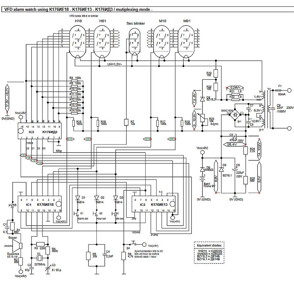
Schaltplan einer VFD-Anzeige mit K176IE18 und K176IE13
VFD alarm watch K176IE18 - K176IE13 - K176ИД13 / multiplexing mode - H10 H01 Sec blinker M10 M01 UH=1,2V~ R2 100k R9 100k R10 100 R11 10k R12 100k R13 100k R14 100k R15 100k R16 100k R7 12k R17 100k R18 100k R20 100 R21 1,8 R22 1,8 C7 22nF R23 840C1500 0,24V~ F1 63mA C9 220nF 230V/1000V R24 12,0V~ C5 470uF/25V R25 22R R26 3,9Ω 0,1V BZY9,1 840C1500 7,9V BZY9,1 0,1V C6 220uF 130V Vcc(+9V) 0V(GND) 0V(GND) M10 M11 M12 M13 M14 M15 M16 M17 M18 M19 M20 M21 M22 M23 M24 M25 M26 M27 M28 M29 M30 M31 M32 M33
in „Reparaturtips für VFD von alter Elektronika-Leuchte“ · Analoge Elektronik und Schaltungstechnik · · Schaltpläne

-
Datei
transceiver_test_v3_twr.html
Delay (ns) Site Resource PADI_DEL --- 0.259 87.PAD to 87.PADDI VCXO_24R ROUTE 1 0.805 87.PADDI to R13C6A.CLK VCXO_24R_c REG_DEL --- 0.137 R13C6A.CLK to R13C6A.Q0 RECEIVER/PLL_MODUL/CLK_DIVIDER/SLICE_78 ROUTE 5 0.394 R13C6A.Q0 to R14C5C.CLK RECEIVER/sync_cnt_i_1 REG_DEL
in „Desig/Routing Probleme bei Lattice MachXO2280“ · FPGA, VHDL & Co. ·
-
PDF
isl5585-1529099.pdf
) grade andAT = 0°C to 85°C for commercial (C) grade, VBL = -24V, VBH = -100V, -85V or -75V, VCC = +3.3V, AGND = BGND = 0V, loop current limit = 25mA. All AC transmission parameters are specified at 600W 2-wire terminating
in „Anschluss eines alten Analigtelefons an einen RasPi für Audio in/out“ · Analoge Elektronik und Schaltungstechnik ·
-
PDF
artesyn2.pdf
Overshoot: At turn on and turn-off None Undershoot: None Safety Ripple and noise: 3.3 V and 5 V 75 mV pk-pk, 5 Hz - 20 MHz (see note 1) 20 mV rms VDE0805/EN60950/IEC950 12V and 15 V 100 mV pk-pk, 30 mV rms UL1950 CSA C22.2 No. 950 Embedded Power for Business-Critical Continuity Rev.10.16.08_121 Output Continued BXB100 Series Ripple and noise: 3.3 V and 5 V 75 mV pk-pk, of 3 5 Hz - 20 MHz (see note 1) 20 mV rms 12V and 15 V 100 mV pk-pk, 30 mV rms Temperature coefficient: ±0.01% / ºC Transient response: ±2.0% max. deviation (see note 2) 170 µs recovery to within
in „Artesyn DCDC Wandler“ · Markt ·
-
PDF
drv8432-1.pdf
15 30 GND_B 12 25 RESET_AB 16 29 GND_A M2 OUT_C PWM_A 17 28 OUT_A M1 13 24 GND_C PWM_C 14 23 GND_D FAULT 18 27 PVDD_A NC 19 26 PVDD_A RESET_CD 15 22 OUT_D PWM_D 16 21 PVDD_D NC 20 25 NC OTW 21 24 BST_A VDD 17 20 BST_D GVDD_B GVDD_A GVDD_C 18
in „Schrittmotor - PWM interface?“ · Mikrocontroller und Digitale Elektronik ·
-
PDF
mb1045_changed.pdf
P0X304 P0X303 3 4 VCC OUT FTSH-125-01-F-DV-K (Samtec) P 1P0X301 P0X302 2 +1V8 EN GND P0H201 2 SM7745HEX-24.0M 2 H2 P R212 +2V8 1 2 2 2 9 5 [R/A] R R P 0 P P RSTI_CSTI0C TR1 2 R209R205 2 BSN20 P 0K7 4K7 0 03 G 0 0 P R R EXT/RF E2P Connector T2 N0I2C10SCL P0TR101 P P N0I2C10SCL0C C RS ITI EXP_IO2 P0R20602 P0R20601