-
Datei
stepper.cpp
class myStepper { public: float periodStart; float periodSet; float tm; float deltaV; float t; HWTimer hwTimer; myStepper() : hwTimer(6-1, 2000, callback(this, &myStepper::fnLedToggle), true) { periodStart = 800.0f; periodSet = 300.0f; tm = 1000000; deltaV = -0.1; t = 0; } void start() { hwTimer.start
in „STM32CubeIDE C++“ · Mikrocontroller und Digitale Elektronik ·
-
PDF
MN-RBXEB-01.pdf
configured. Configuring the hard disk drive controller next. Initializing the bus option ROMs from C800 next. See 95h Table D-7 for additional information. Initializing before passing control to the adaptor ROM 96h at C800. 97h Initialization before the C800 adaptor ROM gains control has completed. The
-
 Bild
Präsentation der S32K5 MCU Architektur
consolidation Mixed criticality Freedom from interference Compute Extension Arm Cortex-R52 core @ 800MHz Platform Cortex-M7 core @ 800MHz Low Power Engine Cortex-M4 @ 200MHz LP SRAM & Peripherals Memory Embedded MRAM Low leakage SRAM Ethernet Acceleration Up to 2.5Gbps 10BaseT1S Ethernet switch MACsec
in „EmbeddedWorld 2025, Tag 1 – im Namen des Mikrocontrollers“ · Mikrocontroller und Digitale Elektronik · · Fotos

-
PDF
EA_4_40.pdf
Time, RS, R/W-E tAS see Figs.1 and 2 140 - - ns Use "74LS" or "74HC" gate Data Delay Time tDDR see Fig.2 - - 320 ns Data Setup Time tDSW see Fig.1 195 - - ns Data Hold Time tH see Fig.1 10 - - ns Data Hold Time tDHR see
in „Cursor setzen LCD Display“ · Mikrocontroller und Digitale Elektronik ·
-
PDF
EA_4_40.pdf
Time, RS, R/W-E tAS see Figs.1 and 2 140 - - ns Use "74LS" or "74HC" gate Data Delay Time tDDR see Fig.2 - - 320 ns Data Setup Time tDSW see Fig.1 195 - - ns Data Hold Time tH see Fig.1 10 - - ns Data Hold Time tDHR see
in „LCD Display Treiber und Einkopplungen“ · Mikrocontroller und Digitale Elektronik ·
-
PDF
CO1.pdf
T E C H N I C A L N O T E PRF-1150 1KW 13.56 MHz CLASS E RF GENERATOR EVALUATION MODULE Abstract The PRF-1150 module is a self-contained 1KW 13.56MHz RF source. The module facilitates operation and evaluation
in „Bauplan für HF Netzteil gesucht.“ · HF, Funk und Felder ·
-
PDF
MPXx6115A.pdf
• MPXHZ6115A MPXHZ6115A6T1 1317 • • MPXHZ6115A MPXHZ6115AC6U 1317A • • MPXHZ6115A MPXHZ6115AC6T1 1317A • • MPXHZ6115A SMALL OUTLINE PACKAGES MPXA6115A6U/T1 MPXA6115AC6U/T1 MPXA6115AC7U MPXAZ6115AP/T1 MPXAZ6115A6U MPXAZ6115AC6U/T1 CASE 482C CASE 1369 CASE 482 CASE 482A SUPER SMALL OUTLINE PACKAGES MPXH6115A6U/T1 MPXH6115AC6U/T1 MPXHZ6115AC6U/T1 MPXHZ6115A6U/T1 CASE 1317 CASE 1317A MPXA6115A Sensors 2 Freescale Semiconductor Pressure
in „(S) Empfehlung für Drucksensoren (MPX? 6115A6U)“ · Mikrocontroller und Digitale Elektronik ·
-
Datei
lcd_init.h
(uint16_t x0, uint16_t y0, uint16_t x1, uint16_t y1, uint32_t color); /* Zeichne einen leeren Kreis */ void LCD_DrawCircle(int16_t x0, int16_t y0, int16_t r, uint32_t color); /* Zeichne einen gefüllten Kreis *
in „Basteltip: STM32F103 DIP40 Board“ · Mikrocontroller und Digitale Elektronik ·
-
Datei
lcd_init.h
(uint16_t x0, uint16_t y0, uint16_t x1, uint16_t y1, uint32_t color); /* Zeichne einen leeren Kreis */ void LCD_DrawCircle(int16_t x0, int16_t y0, int16_t r, uint32_t color); /* Zeichne einen gefüllten Kreis *
in „Lebensdauer von lokalen Variablen“ · Softwareentwicklung ·
-
PDF
SSW-124.pdf
operates at -5V and 0V for control bias. Its high isolation and low insertion loss, makes it ideal for T/R switching in analog and digital wireless communication systems. Product Features The die is fabricated using 0.5 micron FET process with gold metallization and silicon nitride passivation to achieve
in „suche für Rohde&Schwarz SML03 Abschwächerbaugruppe oder IC 4227T“ · Markt ·
-
PDF
241209_A400_Data_Sheet_V1-5.pdf
15.109 (Class A) Manufactured: USA & Europe Network Connections: Dual SIM, GSM/3G/4G/5G, 10/100 Base-T Ethernet Network Communication Open Charge Point Protocol (OCPP) 1.6J and 2.0.1 Protocol: Vehicle Communication DIN SPEC 70121, ISO 15118-2, ISO 15118-3, Autocharge, Protocol: Plug and Charge Short Circuit
in „Batterieheizung durch Ripplestrom“ · Fahrzeugelektronik ·
-
PDF
TL431.pdf
T3C_ Reel of 250 TL431CDBVT SOT-23-5 (DBV) Reel of 3000 TL432CDBVR Reel of 250 TL432CDBVT T4C_ Reel of 3000 TL431CDBZR T3C_ 0°C to 70°C Reel of 250 TL431CDBZT SOT-23-3 (DBZ) Reel of 3000 TL432CDBZR T4C
in „Überspannungsschutz (Crowbar) für XPORT (3.3V)“ · Analoge Elektronik und Schaltungstechnik ·
-
PDF
leitfaden_laserstrahlung.pdf
· t 0,7C C [JEm ] -2 [J m ] [J m ] b 12 -2 c 3 -2 H=5,6·10 t 0,25 1 400 - 1 500 e E = 10 [W m ] Siehe Fußnote H = 10 [J m ] -2 IR-B o [J m ] 1 500 - 1 800 n E = 10 [W m ] -2 Siehe Fußnote c H = 10 [J m ]-2 und ß 3 0,25 IR-C 1 800 - 2 600 F E = 10 [W m ] -2 Siehe Fußnote c H = 10 [J m ]-2 H=5,6·10 -2·t . [J m ] 2 600 - 10 6 S E = 10 [W m ] -2 Siehe Fußnote c H =100 [J m ]-2 H = 5,6 · 10 ·t 0,25[J m ] a Wird die Wellenlänge des
-
Datei
DCF77_Mega88.c
(0<<DDB6) | (0<<DDB5) | (0<<DDB4) | (0<<DDB3) | (0<<DDB2) | (0<<DDB1) | (0<<DDB0); // State: Bit7=T Bit6=T Bit5=T Bit4=T Bit3=T Bit2=T Bit1=T Bit0=T PORTB=(0<<PORTB7) | (0<<PORTB6) | (0<<PORTB5) | (0<<PORTB4) | (0<<PORTB3) | (0<<PORTB2) | (0<<PORTB1) | (0<<PORTB0); // Port C initialization // Function
in „DCF77 Bit0 ermitteln“ · Mikrocontroller und Digitale Elektronik ·
-
PDF
LM2595.pdf
Top e View g l a TL/H/12565–2 TL/H/12565–3 o Order Number LM2595T-3.3, LM2595T-5.0, Order Number LM2595S-3.3, LM2595S-5.0, r LM2595T-12 or LM2595T-ADJ LM2595S-12 or LM2595S-ADJ See NS Package Number T05D See NS Package Number TS5B Patent Number 5,382,918. SIMPLE SWIÉCHER
in „Schaltregler 9-18V input 14-V output“ · Analoge Elektronik und Schaltungstechnik ·
-
PDF
LM2595.pdf
Top e View g l a TL/H/12565–2 TL/H/12565–3 o Order Number LM2595T-3.3, LM2595T-5.0, Order Number LM2595S-3.3, LM2595S-5.0, r LM2595T-12 or LM2595T-ADJ LM2595S-12 or LM2595S-ADJ See NS Package Number T05D See NS Package Number TS5B Patent Number 5,382,918. SIMPLE SWIÉCHER
in „5 Volt 1A fürs auto passiv gekühlt gesucht“ · Analoge Elektronik und Schaltungstechnik ·
-
 Bild
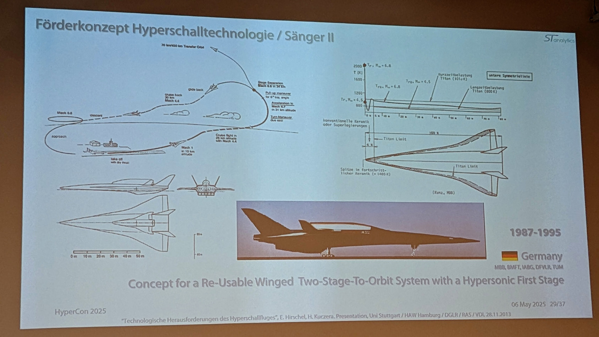
Foto eines Präsentationsplakats zum Hyperschalltechnologie-Förderkonzept
Mach 1 in 10 km altitude Crab flight in 30 km altitude with Mach 4.4 Turn maneuver due to... 2000 T (K) 1600 1200 800 konventionelle Keramik oder Superlegierungen Tra. M=6.8 Tra. M=4.5 Tra. M=6.8 Kurzzeitbelastung Titan (1010 K) Langzeitbelastung Titan (800 K) untere Symmetrieebene Titan Limit Spitze
in „HyperCon 2025 – Beschäftigung für Elektroniker?“ · Fahrzeugelektronik · · Fotos
-
PDF
en.CD00003902.pdf
RC network formed by R and can be added; Figure 1. Electronic transformer for 12V Halogen Lamp R C2 T'1 TR1 T1 D C1 C3 T''1 TR2 AN528/0999 1/4 APPLICATION NOTE C1. This can be varied to provide a lamp dimming 3.1 Short Circuit Protection feature. Figure 2 shows a circuit with circuitry to protect Once
in „Paulmann N 105“ · Analoge Elektronik und Schaltungstechnik ·
-
PDF
an528-electronic-transformer-for-a-12v-halogen-lamp-stmicroelectronics.pdf
RC network formed by R and can be added; Figure 1. Electronic transformer for 12V Halogen Lamp R C2 T'1 TR1 T1 D C1 C3 T''1 TR2 AN528/0999 1/4 APPLICATION NOTE C1. This can be varied to provide a lamp dimming 3.1 Short Circuit Protection feature. Figure 2 shows a circuit with circuitry to protect Once
in „Warum gibt es keine AC-Schaltnetzteile“ · Analoge Elektronik und Schaltungstechnik ·
-
PDF
cd00003902-electronic-transformer-for-a-12v-halogen-lamp-stmicroelectronics.pdf
RC network formed by R and can be added; Figure 1. Electronic transformer for 12V Halogen Lamp R C2 T'1 TR1 T1 D C1 C3 T''1 TR2 AN528/0999 1/4 APPLICATION NOTE C1. This can be varied to provide a lamp dimming 3.1 Short Circuit Protection feature. Figure 2 shows a circuit with circuitry to protect Once
in „Elektronischen Halogen-Trafo auf LED-Betrieb umrüsten“ · Analoge Elektronik und Schaltungstechnik ·
-
PDF
MLX90640-Datasheet-Melexis.pdf
Page 16 of 60 MLX90640 32x24 IR array Datasheet B15 B14 B13 B12 B11 B10 B9 B8 B7 B6 B5 B4 B3 B2 B1 B0 t l o e d e r t t e r l e m r t o o a s h r s s p c e b g t s g r g i r s p d r p Control register 1 - 0x800D x d l h c u l x u l e s r e s a l e M R e e S b E M b R R n n E E 0 No subpages, only one page
in „MLX90640 IR-Array 32x24 pixel“ · Mikrocontroller und Digitale Elektronik ·
-
PDF
MLX90640-Datasheet-Melexis.pdf
Page 16 of 60 MLX90640 32x24 IR array Datasheet B15 B14 B13 B12 B11 B10 B9 B8 B7 B6 B5 B4 B3 B2 B1 B0 t l o e d e r t t e r l e m r t o o a s h r s s p c e b g t s g r g i r s p d r p Control register 1 - 0x800D x d l h c u l x u l e s r e s a l e M R e e S b E M b R R n n E E 0 No subpages, only one page
in „Wärmebildkamera mit dem MLX90640 und Arduino Due“ · Mikrocontroller und Digitale Elektronik ·
-
PDF
RTC4553AP.pdf
90 % S IN 10 % tD tD WR SWR HWR t t S OUT 90 % 10 % tDSZ1 tDSZ2 CS 0 90 % S CK 1 8 1 ts S CK 10 % 90 % S OUT 10 % tDSO CS 1 90 % 10 % TP OUT 90 % 10 % tDPZ1 tPZ2 Page - 6 MQ - 132 - 04 RTC - 4553 8. How to use 8.1. Registers
in „Atmega8, RTC, Uhrzeit und Datum“ · Mikrocontroller und Digitale Elektronik ·
-
PDF
RTC4553AP.pdf
90 % S IN 10 % tD tD WR SWR HWR t t S OUT 90 % 10 % tDSZ1 tDSZ2 CS 0 90 % S CK 1 8 1 ts S CK 10 % 90 % S OUT 10 % tDSO CS 1 90 % 10 % TP OUT 90 % 10 % tDPZ1 tPZ2 Page - 6 MQ - 132 - 04 RTC - 4553 8. How to use 8.1. Registers
in „Eine RTC R4553A am Arduino“ · Mikrocontroller und Digitale Elektronik ·
-
Datei
PINK_TEST.ino
//static const uint16_t PINK = 0xF81F; //static const uint16_t PANK = 0xF81A; //static const uint16_t PUNK = 0xF81B; static const uint16_t PONK = 0xF81C; static const uint16_t BLUE = 0x001F; static const uint16_t RED = 0xF800
in „Arduino "static const uint16_t PINK= 0xF81F" failed“ · Mikrocontroller und Digitale Elektronik ·
-
PDF
CD00277537.pdf
STM32L152x6/8/B Electrical characteristics Figure 22. SPI timing diagram - slave mode and CPHA = 0 NSS input t c(SCK) t t SU(NSS) h(NSS) u CPHA=0 I CPOL=0 t K CPHA=0 w(SCKH) C CPOL=1 w(SCKL) S t t t t t a(SO) v(SO) h(SO) tr(SCK) dis(SO) f(SCK) MISO OUTPUT MSB O UT BIT6 OUT LSB OUT su(SI) MOSI MSB IN BIT1 IN LSB
in „SPI-Schnittstelle Befehl: SPI_I2S_SendData(spi2, data)“ · Mikrocontroller und Digitale Elektronik ·
-
PDF
sq277.pdf
Rise time of both R --- 0.3 SDA and SCL Fall time of both SDA and SCL F --- 0.3 Setup time for t 0.6 STOP condition SU.STO tSU;DAT tHD;DAT SU;STA HD;STA tR tF SCL SDA HIGH tLOW tSU;STO tBUF tHD;STA SCL SDA FIGURE II: Timing characteristics of the serial interface October 2007 / 646 5/11 www.sensortechnics.com
in „I2C Kommunikation zwischen Atmega128 und Drucksensor“ · Mikrocontroller und Digitale Elektronik ·
-
Datei
quick5000.h
uint16_t spuelwasser =0; uint16_t einzelwasser=0; uint16_t einzelpulver=0; uint16_t doppelwasser=0; uint16_t doppelpulver=0; uint16_t eeteewasser EEMEM =800; uint16_t eespuelwasser EEMEM =300; uint16_t eeeinzelwasser EEMEM =100; uint16_t eeeinzelpulver EEMEM =80; uint16_t eedoppelwasser EEMEM =400; uint16_t eedoppelpulver EEMEM =60;
in „Bau einer Kaffee-Vollautomaten Steuerung“ · Mikrocontroller und Digitale Elektronik ·
-
PDF
Beschreibung.pdf
PCB. The TVS diodes 1N5908 are not necessarily required. (note) If the TFT display is used: • Don't buy the rotary switch S5. • Buy 1 tactile switch. • Don't buy LED1. If a part is out of stock at Conrad, take the alternative, see below: Conrad number / QtyValue Parts Descriptionalternative 3 100nF
in „Nach dem Trafo, nun die Punktschweißmaschine“ · Mechanik, Gehäuse, Werkzeug ·
-
PDF
Display.pdf
PINS MIN. MAX. UNIT Address hold time tH8 CSB 160 ns Address setup time AS8 RS 160 ns System cycle time tCYC8 1 800 ns Read pulse width (READ) tRDW8 RDB 1 000 ns WRB Write pulse width (WRITE) WRW8 400 ns Data setup time DS8 D7-D0 400 ns Data
in „LC-Display Sharp M078CKA ansteuern“ · Mikrocontroller und Digitale Elektronik ·
-
PDF
lh155.pdf
PINS MIN. MAX. UNIT Address hold time tH8 CSB 160 ns Address setup time AS8 RS 160 ns System cycle time tCYC8 1 800 ns Read pulse width (READ) tRDW8 RDB 1 000 ns WRB Write pulse width (WRITE) WRW8 400 ns Data setup time DS8 D7-D0 400 ns Data
in „Suche sehr dünnes Grafikdisplay“ · Mikrocontroller und Digitale Elektronik ·
-
PDF
lh155.pdf
PINS MIN. MAX. UNIT Address hold time tH8 CSB 160 ns Address setup time AS8 RS 160 ns System cycle time tCYC8 1 800 ns Read pulse width (READ) tRDW8 RDB 1 000 ns WRB Write pulse width (WRITE) WRW8 400 ns Data setup time DS8 D7-D0 400 ns Data
-
PDF
lg_flatron_l1800p_lb886f_ch_cl-29.pdf
3 16 75Hz H – 43.269 832 640 56 56 80 5 36.0 640x480 V – 85.0 509 480 1 3 25 85Hz H + 37.879 1056 800 40 128 88 800x600 6 V + 40.0 60.317 628 600 1 4 23 60Hz H + 46.875 1056 800 16 80 160 800x600 7 49.5 75Hz V + 75.0 625 600 1 3 21 H + 53.674 1048 800 32 64 152 800x600 8 56.25 85Hz V + 85.061 631 600
in „Überspannung in Mehrparteien-Wohunung. Baustrom, oder Kabel angebohrt?“ · Haus & Smart Home ·
-
PDF
Littelfuse_TVS_Diode_P6KE_Datasheet.pdf
max e s(max) t TS(max)oT L Ramp-up Rate 3°C/second max r Ramp-down pTs(min) -Temperature (T L (Liquidus) 217°C e s Reflow T Preheat -Time (min to max) (t L 60 – 150 seconds +0/-5 PeakTemperature (T ) P 260 °C 25˚C t 25˚C to Peak Time within 5°C of actual peakTemperature (t ) p 30 Seconds Max Time (t) Ramp-down Rate 6°C/second max Time 25°C to peakTemperature (T ) P 8 minutes Max. Do not exceed 260°C Flow/Wave Soldering
in „PhotoMos mit TVS schützen ?“ · Analoge Elektronik und Schaltungstechnik ·
-
PDF
Q67060-S6302-A2.pdf
operation V OUT1 V OUT1 IL1 channel 1: open load channel 1: L1 open normal open load load load ST t d(ST) d(ST) td(ST OL5) t d(ST OL1) td(ST OL2) t d(ST OL1) t d(ST OL2) t ST t td(ST OL5)pends on external circuitry because of high impedance d(ST OL1)30 s typ.,d(ST OL2)20 s typ Semiconductor Group 12
in „Problem mit Openload bei BTS611L1“ · Mikrocontroller und Digitale Elektronik ·
-
PDF
185345-da-01-en-SMD_BTS611L1.pdf
operation V OUT1 V OUT1 IL1 channel 1: open load channel 1: L1 open normal open load load load ST t d(ST) d(ST) td(ST OL5) t d(ST OL1) td(ST OL2) t d(ST OL1) t d(ST OL2) t ST t td(ST OL5)pends on external circuitry because of high impedance d(ST OL1)30 s typ.,d(ST OL2)20 s typ Semiconductor Group 12
in „Doppel-Power-FET (BTS 611)“ · Analoge Elektronik und Schaltungstechnik ·
-
PDF
XPort_reference_design_and_guidelines.pdf
Ceramic, X7R, 1206 SMD BC Components 1206B104K500BT C19 1 C9 Capacitor, 4.7uF, 35V, 7343 SMD Kemet T491D475K035AS 2 C10,C11 Capacitor, 22uF, 16V, 7343 SMD Kemet T494D226K016AS D1,D2,D3,D4,D5,D6,D7,D8 CMD15- 10 ,D10,D12 LED, Red, 1206 SMD Panasonic 21SRC/TR8 1 D9 LED, Bicolor, Green/Red, 1210 SMD Lite-On
in „Lantronix X-Port beschalten“ · Mikrocontroller und Digitale Elektronik ·
-
PDF
MG_Model_B__C___D_3_phase_kw.pdf
model B, C and D - 3 phase Flange B35, B5/V1 Flange B34, B14/V18 Cable entry HC HD K LA M N P SxZ T LA M N P SxZ T O p s c1 e1 b1 a1 s1 f1 c1 e1 b1 a1 s1 f1 142 180 7 (M6) 10 130 110 160 M6 x 4 3.50 121) 85 70 105 M6x4 2.50 2 x M20 x 1.5 MG 80 151 189 10 (M8) 10 165 130 200 M6 x 4 3.50 121) 100 80
in „3Phasen Motoer an FU - Lagergeräusche?“ · Analoge Elektronik und Schaltungstechnik ·
-
PDF
PDFsam_panasonic_rf-d10eb_service_manual.pdf
100 R202 4.7K 4 5 4 5 4 5 C 1 2 8 7 2 9 4 R120 C203 C C C C C C 2 2 LB203 C 4 3 8 8 8 8 1 0 R 3 2 T1 64 63 62 61 60 59 5857 5655 5453 52 51 5049 C C 8 2 2 C C C C R C . 2 P N P T B B 2 3 1 2 S O K D 0 C R R 2 3 2 0 1 1 C201 4.7 S S E U U 1 E _ D T T T T 0 1 . C C 1 U U E I I D O S P BCLK 48 C 0 C202
in „Welche Fritzbox hat die meisten Spannungswandler?“ · Analoge Elektronik und Schaltungstechnik ·
-
Datei
PWMtest.c
=T State4=T State3=T State2=T State1=T State0=T PORTC=0x00; DDRC=0x00; // Port D initialization // Func7=In Func6=In Func5=In Func4=In Func3=In Func2=In Func1=In Func0=In // State7=T State6=T State5=T State4=T State3=T State2=T State1=T State0=T PORTD=0x00; DDRD=0x00; // Timer/Counter 0 initialization // Clock source: System Clock // Clock value: 10,800 kHz // Mode: Phase correct PWM top=FFh // OC0 output:
in „PWM mit Atmega32 (in C)“ · Mikrocontroller und Digitale Elektronik ·
-
Datei
Settings.c
EEPROM_Read32(FLASHoffset + 0x0E4,&Motor_Drehzahl_Running); EEPROM_Read32(FLASHoffset + 0x0E8,&Motor_t_Shutdown); EEPROM_Read32(FLASHoffset + 0x0EC,&Motor_t_Blockiert); EEPROM_Read32(FLASHoffset + 0x0F0,&Motor_t_AnlassenMax); EEPROM_Read32(FLASHoffset + 0x0F4,&Motor_t_Abkuehlen); } /* Speichert alle Einstellungen
in „Datenverlust in EEPROM“ · Mikrocontroller und Digitale Elektronik ·
-
PDF
LB084S02-TD01.pdf
SPECIFICATION FOR APPROVAL ( ) Preliminary Specification ( ) Final Specification Title 8.4” SVGA (800 x RGB x 600) TFT LCD BUYER SUPPLIER LG.Philips LCD Co., Ltd. MODEL LB084S02 MODEL Suffix TD01 SIGNATURE DATE SIGNATURE DATE S.D. JUNG / G.Manager / REVIEWED BY / J.Y. KIM / Manager PREPARED BY / O.J
-
PDF
BTS621-INF.pdf
Vbb V bb ON(CL) Vbb(over) bb(o rst) V Vbb(under) bb(u cp) Vbb(u rst) V OUT V OUT ST ST open drain t t Figure 6b: Undervoltage restart of charge pump V VON(CL) on t t t s t t f - V - o o bb(over) o V Vbb(o rst) bb(u rst) V bb(u cp) V bb(under) V bb charge pump startbb(ucp).6 V typ. Semiconductor Group
in „Schalten mit einem BTS621“ · Analoge Elektronik und Schaltungstechnik ·
-
PDF
bts621.pdf
Vbb V bb ON(CL) Vbb(over) bb(o rst) V Vbb(under) bb(u cp) Vbb(u rst) V OUT V OUT ST ST open drain t t Figure 6b: Undervoltage restart of charge pump V VON(CL) on t t t s t t f - V - o o bb(over) o V Vbb(o rst) bb(u rst) V bb(u cp) V bb(under) V bb charge pump startbb(ucp).6 V typ. Semiconductor Group
in „Atmega8 Portpin VCC-loss sicher machen“ · Mikrocontroller und Digitale Elektronik ·
-
Datei
LCD.h
_t Ypos,uint8_t c,uint16_t charColor,uint16_t bkColor); void LCD_DrawLine( uint16_t x0, uint16_t y0, uint16_t x1, uint16_t y1 , uint16_t color ); void PutChinese(uint16_t Xpos,uint16_t Ypos,uint8_t *str,uint16_t Color,uint16_t bkColor); void GUI_Text(uint16_t Xpos, uint16_t Ypos, uint8_t *str,uint16_t Color, uint16_t bkColor); void GUI_Chinese(uint16_t Xpos, uint16_t Ypos, uint8_t *str,uint16_t Color, uint16
in „STM32F4 mit TFT Codeverständnis“ · Mikrocontroller und Digitale Elektronik ·
-
Datei
LCD.h
_t Ypos,uint8_t c,uint16_t charColor,uint16_t bkColor); void LCD_DrawLine( uint16_t x0, uint16_t y0, uint16_t x1, uint16_t y1 , uint16_t color ); void PutChinese(uint16_t Xpos,uint16_t Ypos,uint8_t *str,uint16_t Color,uint16_t bkColor); void GUI_Text(uint16_t Xpos, uint16_t Ypos, uint8_t *str,uint16_t Color, uint16_t bkColor); void GUI_Chinese(uint16_t Xpos, uint16_t Ypos, uint8_t *str,uint16_t Color, uint16
in „STM32F4 Discovery + TFT + FSMC“ · Mikrocontroller und Digitale Elektronik ·
-
PDF
14223_ADI_ADP2108.pdf
synchronous rectifier. Rev. C | Page 5 of 20 ADP2108 TYPICAL PERFORMANCE CHARACTERISTICS V IN3.6 V, T = 2A°C, V = V , uENess otINrwise noted. 24 1400 +85°C 1300 22 ) µ 1200 ( A N 20 m E +25°C T1100 R I U I C 18 L1000 T N E –40°C E C R 900 S 16 U I C Q 800 14 700 12 600 2.5 3.0 3.5 4.0 4.5 5.0 5.5 0 2.7
in „Reflowlöten - Bastlermethode mit Cerankochfeld und Infrarot-Thermometer (bestes Vorgehen gesucht)“ · Platinen ·
-
PDF
14223_ADI_ADP2108.pdf
synchronous rectifier. Rev. C | Page 5 of 20 ADP2108 TYPICAL PERFORMANCE CHARACTERISTICS V IN3.6 V, T = 2A°C, V = V , uENess otINrwise noted. 24 1400 +85°C 1300 22 ) µ 1200 ( A N 20 m E +25°C T1100 R I U I C 18 L1000 T N E –40°C E C R 900 S 16 U I C Q 800 14 700 12 600 2.5 3.0 3.5 4.0 4.5 5.0 5.5 0 2.7
in „WLCSP von Analog Devices, Wie erkennt man die PIN-Markierung?“ · Platinen ·