-
 Bild
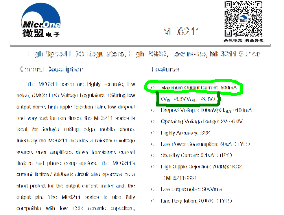
Datenblatt der MB6211 LDO Regler Serie
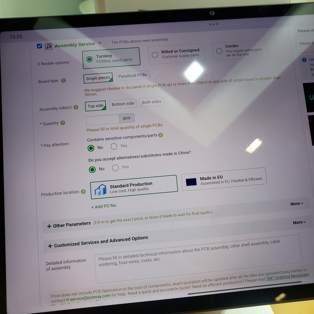
MicrOne 微盟电子 MB6211 High Speed LDO Regulators, High PSRR, low noise, MB6211 Series. Maximum Output Current: 500mA (VIN: 4.5V, VOUT: 3.3V). Dropout Voltage: 100mV@ Iout=100mA. Operating Voltage Range: 2V~6.0V. Highly Accuracy: ±2%. Low Power Consumption: 40uA (TYP.). Standby Current: 0.1uA (TYP.). High Ripple Rejection: 70dB@1KHz (MB6211C/B). Low output noise: 50uVrms. Line Regulation: 0.05% (TYP.)
-
 Bild
Datenblatt der MB6211 LDO Regler Serie
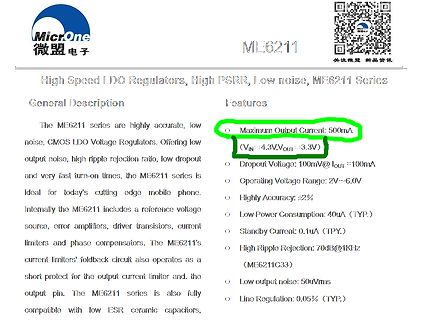
MicrOne 微盟电子 MB6211 High Speed LDO Regulators, High PSRR, low noise, MB6211 Series. Maximum Output Current: 500mA (VIN: 4.5V, VOUT: 3.3V). Dropout Voltage: 100mV@ Iout=100mA. Operating Voltage Range: 2V~6.0V. Highly Accuracy: ±2%. Low Power Consumption: 40uA (TYP.). Standby Current: 0.1uA (TYP.). High Ripple Rejection: 70dB@1KHz (MB6211C/B). Low output noise: 50uVrms. Line Regulation: 0.05% (TYP.)
-
 Bild
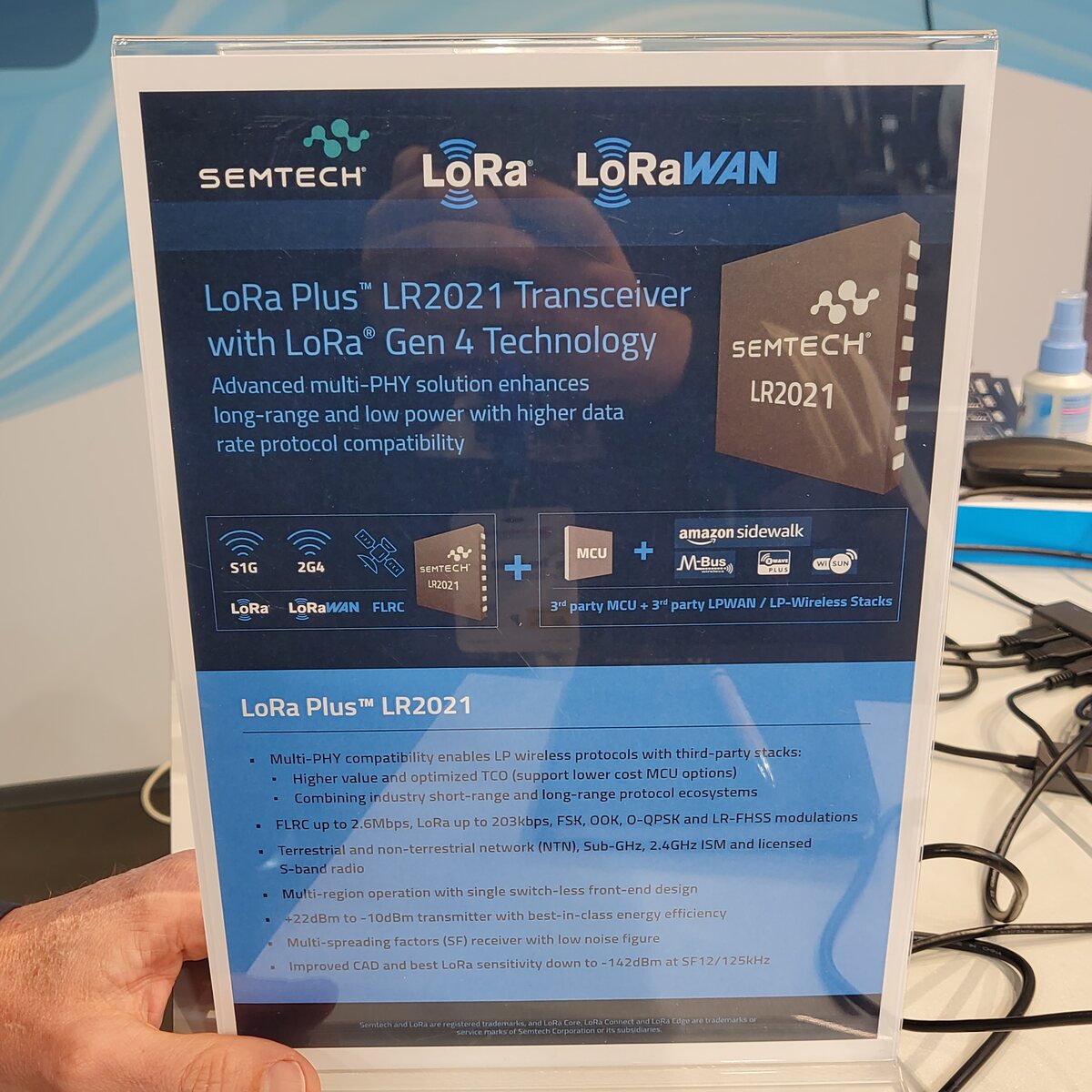
Werbeaufsteller für Semtech LR2021 Transceiver
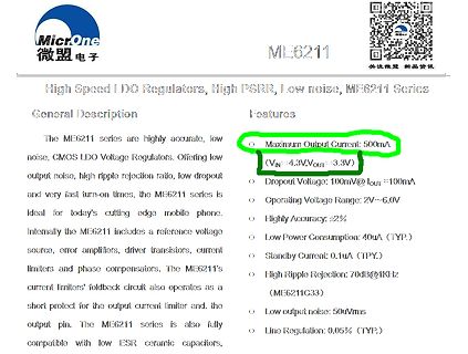
LR2021 Transceiver with LoRa® Gen 4 Technology Advanced multi-PHY solution enhances long-range and low power with higher data rate protocol compatibility SEMTECH LR2021 5G 2G4 LoRa LoRaWAN FLRC MCU + amazon sidewalk M-Bus FLIRC LoRaWAN 3rd party MCU + 3rd party LPWAN / LP-Wireless Stacks LoRa Plus™ LR2021 Multi-PHY compatibility enables LP wireless protocols with third-party stacks; Higher value and optimized TCO (support lower cost MCU options); Combining industry short-range and long-range protocol ecosystems; FLRC up to 2.6Mbps, LoRa up to 203kbps, FSK, OOK, QPSK and LR-FHSS modulations
-
 Bild
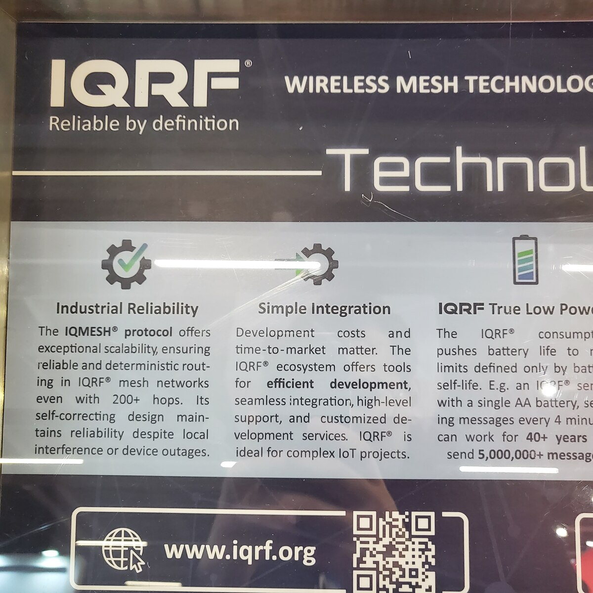
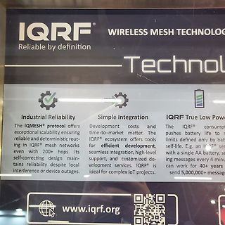
Werbeaufnahme von IQRF Wireless Mesh Technologie
time-to-market matter. The IQRF ecosystem offers tools for efficient development, seamless integration, high-level support, and customized development services. IQRF is ideal for complex IoT projects. IQRF True Low Power The IQRF consumption pushes battery life to remarkable limits defined only by battery
-
 Bild
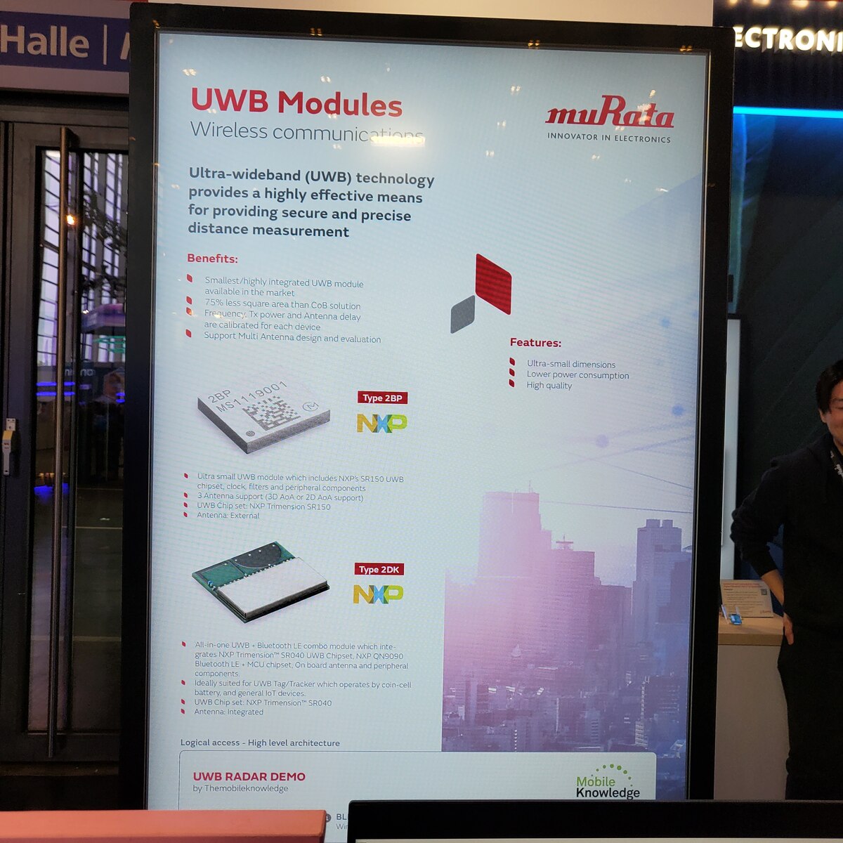
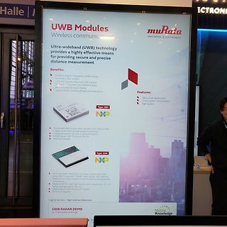
Werbeplakat für UWB Module von Murata
Support: Multi-Antenna design and evaluation Type 2BP MS-1190D1 NXP Features: Ultra-small dimensions Lower power consumption High quality Ultra small UWB module which includes NXP SR150 UWB chipset, lock, filters and peripheral components Antenna support (3D AoA or 2D AoA support) UWB Direction: NXP Trimension
-
Thread
Raspberry Pi Pico SDR
, geht die Abstimmung so wie ich mir das vorgestellt habe. Offensichtlich haben diese Widerstände High und Low so verbeult dass der Pico Fehler machte. So ärgerlich der Fehler ist, aber ich dürfte nicht der einzige sein der dieses Teil in dieser Schaltung verbaut hat. Er war auf der Webseite für den
das noch einstellen lässt. Danke, ich habe das unter "Encoder Resolution" gefunden .Habe das von "Low" auf "High" gestellt. Jetzt passt das wieder.
-
Thread
EmbeddedWorld 2025, Tag 3 – im Strom der Komponenten, FPGAs und mehr
addition of the RZ/V2N, the RZ/V series has now expanded to cover a full range of markets, from the low-end RZ/V2L (0.5TOPS) to the high-end RZ/V2H (up to 80 TOPS). The new MPU is significantly smaller than the RZ/V2H, with its package area measuring only 15 mm square, reducing the area required for mounting by 38%. Inheriting the advanced features of the RZ/V series, the RZ/V2N combines high AI performance with low power consumption [/c]  Bildquelle: Renesas, via https://www.renesas.com/en/about/newsroom/renesas-extends-mid-class-ai-processor-line-rzv2n-integrating-drp-ai-accelerator-smart-factories-and
-
 Bild
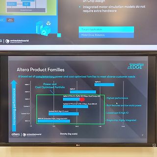
Foto eines Bildschirms mit Altera Produktfamilien Diagramm
3.0, Tx/Rx 12.5 Gbps, Dual Cortex A55 Cyclone V PCIe 2.0, Tx/Rx 6 Gbps, Dual ARM A9 Cyclone 10 LP: High I/O count MAX 10: Embedded Flash, integrated ADC Increasing performance Density (log scale) Highest performance Rich features and low static power Lowest cost & high IO Single chip, highly integrated
-
 Bild
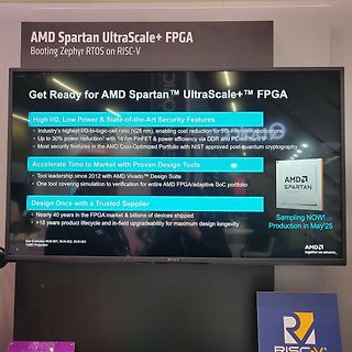
Foto einer Präsentationsfolie über AMD Spartan UltraScale+ FPGA
Spartan UltraScale+ FPGA Booting Zephyr RTOS on RISC-V Get Ready for AMD Spartan™ UltraScale+™ FPGA High I/O, Low Power & State-of-the-Art Security Features Accelerate Time to Market with Proven Design Tools Design Once with a Trusted Supplier Sampling NOW! Production in May'25 AMD together we advance_
-
 Bild
Abfotografierter Monitor mit AMD FPGA Portfolio Übersicht
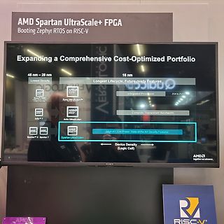
Booting Zephyr RTOS on RISC-V Expanding a Comprehensive Cost-Optimized Portfolio 45 nm - 28 nm 16 nm Lowest Density Longest Lifecycle, Future-ready Features Zynq 7000 Integrated Processor Zynq UltraScale+ ZUX to ZU19 Artix 7 Artix UltraScale+ Compute, Transceiver Bandwidth Artix 7 Spartan 6 Spartan 7 Spartan UltraScale+ High I/O, Low Power, State-of-the-Art Security Features Device Density (Logic Cell) AMD together we advance...
-
 Bild
Abfotografierter Bildschirm mit onsemi Smart iToF Präsentation
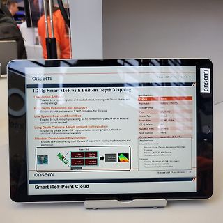
onsemi onsemi 2025 | Public Information | db 1.2Mp Smart iToF with Built-In Depth Mapping Low Motion Artifacts High Depth Resolution and Accuracy Low System Cost and Small Size Long Depth Distance & High ambient light rejection Standard Development Environment Specifications Feature Value Resolution
-
 Bild
Nuvoton M55M1 MCU AI Pose Detection Display
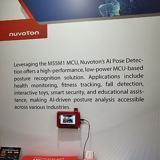
nuvoton Leveraging the M55M1 MCU, Nuvoton's AI Pose Detection offers a high-performance, low-power MCU-based posture recognition solution. Applications include health monitoring, fitness tracking, fall detection, interactive toys, smart security, and educational assistance,
-
Thread
Zustand TLE4935 dem Einschalten
geplant. Jetzt ist aber für mich ein Frage offen. Welchen Zustand hat der TLE4935 nach dem Einschalten. Low oder high? Im Datenblatt steht dazu nichts und meine ersten versuche haben gezeigt, dass er LOW schaltet. Das ist natürlich wichtig, dass die Zündspule nicht gleich eingeschaltet wird, wenn der Schlüssel
es sich um einen bipolaren mit Latch. Das heißt, bei einem Feld von mehr als 10mT schaltet er auf Low (open collector leitend) und bei -10mT schaltet er wieder aus.
-
Thread
CAN Terminator IC
einem IC übernommen wird. Meine Vorstellung wäre ein kleiner Chip, z.B. ein SOT23-5 mit 5V0, Gnd, CAN-High, CAN-LOW und einem Input mit dem man die Terminierung ein- bzw. ausschalten kann. Wenn die Terminierung (durch den GPIO) aktiviert ist, soll der Chip eine CAN-Terminierung gem. dem "Split Termination
-
 Bild
Oszilloskop-Messung einer 1N4007 Diode
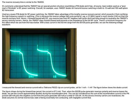
1N4007 takes advantage of the lengthy reverse recovery period, which prevents it from rectifying the high frequency signal it is switching. (This is because the reverse voltage half-cycle period of, say, a 3.5 MHz signal is much shorter (140 ns) than the reverse recovery time. Hence, if forward biased with
-
 Bild
Verschiedene Display-Ansichten eines Messgeräts
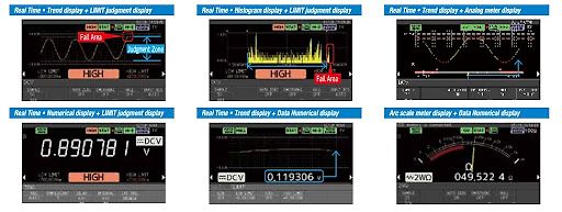
Real Time + Trend display + LIMIT judgment display Fall Area Judgment Zone HIGH LOW LIMIT HIGH LIMIT Real Time + Histogram display + LIMIT judgment display Fall Area HIGH LOW LIMIT HIGH LIMIT Real Time + Trend display + Analog meter display Real Time + Numerical display + LIMIT judgment display 0.890781 V HIGH LOW LIMIT HIGH LIMIT Real Time + Trend display + Data Numerical display 0.119306 V DCV Arc scale meter display + Data Numerical display 049.522 Ω
-
 Bild
Abfotografierter Bildschirm einer PCB-Assembly-Webseite
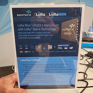
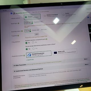
you accept alternatives/substitutes made in China? No Yes Production location: Standard Production Low cost, High quality Made in EU Assembled in EU, Flexible & Efficient + Add PO No. More + Other Parameters (Fill in to get the exact price, or leave it blank to wait for final quote.) More + Customized
-
Thread
Betreibt jemand den 68HC001 im 8 Bit Modus?
Korrektur: Mode muss low sein für 8bit Betrieb.
und ist daher auch die geforderten 2 Takte nach Reset noch stabil. Der Pin muss für 8 bit-Betrieb low sein, Motorola schreibt hierzu "If this input is grounded at reset, the processor will come out of reset in the 8-bit mode. If this input is tied high or floating at reset, the processor will come out
-
Thread
fumot 12.000-Puffs Einweg-Vape mit LED-Display
Reihe haben sie eine nutzbare Spannung von rund 6V bis 8,4V. Den Tiefentladeschutz übernimmt die "Low-Bat" Anzeige des Gerätes. Laden kann man sie, einzeln, über den Chip der ursprünglichen Vape, oder zusammem über ein geeignetes Ladegerät. Keinen DC/DC-Wandler zu verwenden vermeidet dessen Störungen
dafür gibts das Segmentblatt dazu, müsste dann angepasst werden (linke ziffer ist lowpin, rechte high).
-
Thread
suche Datasheed von IC
can function as an alarm IC7. It is used in oscillator circuits, specifically as a LVCMOS XO (Low Voltage Complementary Metal Oxide Semiconductor Crystal Oscillator)3. It operates within a voltage range of 2.25V to 3.63V35. The component is available for purchase from various suppliers
https://ww1.microchip.com/downloads/aemDocuments/documents/TCG/ProductDocuments/DataSheets/DSC12x1-High-Performance-CMOS-MEMS-Oscillator-DS20006010.pdf Wieweit das kompatibel ist weiß nur die völlig perplexe KI
-
 Bild
Abfotografierte Präsentationsfolie von Infineon
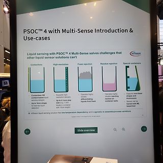
PSOC™ 4 Multi-Sense solves challenges that other liquid sensor solutions can't infineon Contactless High-resolution Foam rejection Residue rejection Special containers - Contactless OR contact-based liquid sensing designs - Up to 3mm airgap for low-res liquid detection - Supports high-resolution designs
-
Thread
DI mit geringer Stromaufnahme und hoher Spannungsfestigkeit
Hysterese verwenden. Eigentlich sollte man für 24V Signale eh eine kräftige Hysterese einplanen. Bspw. Low entspricht < 9V und High entspricht > 15V. Für die Versorgung des OpAmp und sonstigem Hühnerfutter nimmt man kleine DC/DC-Wandler (Recom, Traco, Floeth,...). Das Ausgangssignal vom Komperator kann
-
 Bild
Anschlussdiagramm AM/AMV zwei Wicklungen
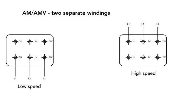
AM/AMV - two separate windings L1 L2 L3 2U 2V 2W 1U 1V 1W Low speed L1 L2 L3 2U 2V 2W 1U 1V 1W High speed
-
Thread
HCI-Kommandos im ESP32, neue Mikrocontroller und Programmierwerkzeuge
unbekannt ist, wie sich dies auf die Sicherheit von ESP-TEE auswirkt. ### Seeed Studio – WiFi HaLow-Module im Angebot Nachdem QuecTel und Co WiFi HaLow-Module in den Markt warfen, folgen die bekannten Hersteller von Evaluationsboards. Im Hause Seeed Studio gibt es – wie in der Abbildung gezeigt –
mitbringt. 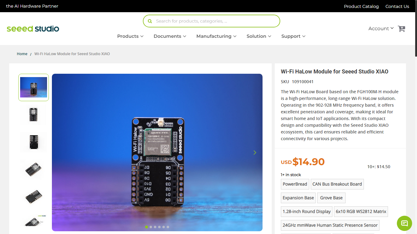 Bildquelle: https://www.seeedstudio.com/Wio-WM6180-Wi-Fi-HaLow-Module-for-XIAO-p-6395.html Unter der URL https://www.seeedstudio.com/Wio-WM6180-Wi-Fi-HaLow-mini-PCIe-Module-p-6394.html findet sich dann ein zweites und ähnlich bepreistes Modul, das allerdings
-
 Bild
Produktseite Wi-Fi HaLow Module für Seeed Studio XIAO
products, categories, ... Products Documents Manufacturing Solution Support Account Home / Wi-Fi HaLow Module for Seeed Studio XIAO Wi-Fi HaLow Module for Seeed Studio XIAO SKU 109100041 The Wi-Fi HaLow Board based on the FGH100M-H module is a high-performance, long-range Wi-Fi HaLow solution. Operating
-
Artikel
Entwicklung eines Motorsteuergerätes für den Trabant
beschriebene Transistorschaltung. Schaltet nun der Geber die Signalleitung auf Masse, wird am Eingang ein Low-Signal gemessen und über die Event-Request-Unit ein High-Signal auf den Ausgang gegeben. Dadurch schaltet der BC547C seine Kollektor-Emitter-Strecke durch und verbindet die Signalleitung der Transistorzündanlage
ist die Signalleitung durch den Geber offen und der PullUp zieht den Mikrocontrollereingang auf ein High-Signal, welches über die Event-Request-Unit als Low-Signal auf den Ausgang gelegt wird. Die Kollektor-Emitter-Strecke am Transistor ist dadurch gesperrt und die Signalleitung zur Transistorzündlage
-
Thread
PWM glätten und Minus als Steuersignal nutzen
zwischen deinen 2 Zeichnungen? Die Schaltung mit dem Relais spricht abrupter an, also der Übergang von Low auf High ist knackiger. Stefan H. schrieb im Beitrag #7843349: > wenn ich 3 parallel schalte, habe ich dann die gewünschten 1µF? Ja.
Beitrag #7843356: > Die Schaltung mit dem Relais spricht abrupter an, also der Übergang von > Low auf High ist knackiger. Gut, das ist nicht wichtig. Ich würde eh über den Shelly ein Fade-In und -Out programmieren. Würde es eigentlich funktionieren, wenn ich das Gedöns mit C1 und R2 auf der
-
Thread
Arduino: digitalRead in Interrupt ist unzuverlässig
von high nach low aus dem Geschwindigkeitsausgang, während der Richtungsausgang jetzt high sein müsste, kann es sein, dass der Puls in die falsche Richtung gezählt wird, weil das Richtungssignal noch dabei ist
Magnet in deren Richtung gedreht ist. Also gibt es zwei "Buttons" (C1 & C2), die entweder gleichzeitig HIGH sind oder nur eine HIGH andere LOW. Wenn beide HIGH, dreht es sich in Uhrzeiger, wenn der C1 HIGH und C2 LOW, dann dreht es sich gegen die Uhrzeiteger. Ich danke euch vielmals für euren Input und
-
Thread
Störsignale Drehzahlmessung filtern
pos. > Pulses eine Mindestlänge hat. Kürzer wird verworfen. Habe ich versucht: [c] durationHigh = pulseIn(DrehzahlsensorPin, HIGH, 40000); mb.task(); durationLow = pulseIn(DrehzahlsensorPin, LOW, 50000); mb.task(); if (durationHigh > 10){ samples.add(durationHigh + durationLow
Konrad B. schrieb im Beitrag #7841762: > Habe ich versucht: durationHigh = pulseIn(DrehzahlsensorPin, HIGH, > 40000); > mb.task(); > durationLow = pulseIn(DrehzahlsensorPin, LOW, 50000); > mb.task(); > if (durationHigh > 10){ > samples.add(durationHigh
-
 Bild
Schaltplan eines Lüfteranschlusses mit Tachoausgang
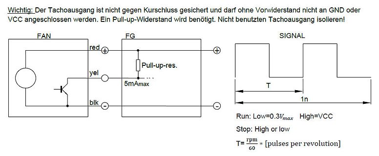
benötigt. Nicht benutzten Tachoausgang isolieren! FAN red yel blk FG Pull-up-res. 5mAmax SIGNAL T 1n Run: Low=0.3Vmax High=VCC Stop: High or low T=rpm/60 * [pulses per revolution]
-
Thread
STM32U3 / STM32WBA6 vorgestellt, neue Raspberry Pi Compute Modules und Steuerrechtliches
Congress sorgt auch bei STMicroelectronics für Aktivität. Mit der STM32U3 schickt man einen neuen Low Power-Mikrocontroller ins Rennen, während der STM32WBA6 mehr Speicher mitbringt. Die Uptoniten erweitern derweil den Temperaturbereich ihrer Compute Modules, während im Bereich des chinesischen Steuerrechts Neuerungen anstehen. ### STM32U3 - neue Ultra-Low-Power-Mikrocontroller. Sowohl Renesas als auch STMicroelectronics rittern mit harten Bandagen und lautem Gewefze um die Krone des Niedrig-Energie-Mikrocontrollers-Hügels.