-
Datei
usartm8.c
/* Testprogramm für FT232RL-Beschaltung an ATmega8 * Es soll ein einzelnes, via USART empfangenes Byte inkrementiert zurück- * gesand werden. */ #include <stdint.h> #include <avr/io.h> #include <avr/interrupt.h> #define F_CPU 8000000 #define BAUDRATE
in „Ist mein ATmega8-Code falsch oder der FT232RL kaputt?“ · Mikrocontroller und Digitale Elektronik ·
-
Datei
ENCODE.C
*************************************/ #include <avr\io.h> #include <avr\interrupt.h> // target: ATmega16 //------------------------------------------------------------------------ #define XTAL 8e6 // 8MHz #define PHASE_A (PINA & 1<<PA1) #define PHASE_B (PINA & 1<<PA3) #define LEDS_DDR DDRC #define LEDS
in „Drehgeber/Encoder 1-, 2- oder 4-schrittig“ · Projekte & Code ·
-
Datei
uart.c
#include "uart.h" void UartInit(void) { //UBRRH = (uint8_t)(UART_UBRR_CALC(UART_BAUD_RATE,F_CPU)>>8); //UBRRH = (uint8_t)(UART_BAUD_RATE>>8); //UBRRL = (uint8_t)UART_UBRR_CALC(UART_BAUD_RATE,F_CPU); //UBRRL = (uint8_t)UART_BAUD_RATE; UBRRH = 00; UBRRL = 12
in „Zähler & Interrupt auslösen ATmega32“ · Mikrocontroller und Digitale Elektronik ·
-
Datei
Bemerkungen.txt
auslesen-------------- >>>: avrdude -C "D:\Dude\avrdude.conf" -u -c usbasp-clone -P usb -b 19200 -p m8 WARNING: Unable to detect MCU avrdude.exe: warning: cannot set sck period. please check for usbasp firmware update. avrdude.exe: error: program enable: target doesn't answer. 0 avrdude.exe: initialization
in „Arduino Mega 2560 Pro Mini - Arduino des Grauens!“ · Mikrocontroller und Digitale Elektronik ·
-
PDF
CF-Karte.pdf
Hardwarebeschreibung, Portadressen Seite 4 …........... Moppel-Softwaree Seite 6 …........... AVR-Software Seite 8 …........... Schaltbilder ECB/AVR Teil Seite 9 …........... Schaltbild Parallelinterface Anlagen: Quellcode Moppel (Auszug aus FDC-Routinen) AVR Seite: 1 von 9 Beschreibung: Mit dieser Interfacekarte
in „Suche MOPPEL Projekt in Heft oder .PDF“ · Mikrocontroller und Digitale Elektronik ·
-
Datei
servo.c
PD2), stores the value and creatres the same signal on PB0. Software: AVR-GCC to compile Hardware: ATMEGA8 (8Mhz) Note: */ #include <avr/io.h> #include <avr/signal.h> #include <avr/interrupt.h> #include <inttypes.h> void input (uint16_t x); // Prototype uint16_t PulsL; int main(void) { DDRB=0xFF; // use
in „PWM 50HZ 1.5ms (Servo)“ · Mikrocontroller und Digitale Elektronik ·
-
Datei
USART_WM.h
keine Übergabeparameter Beschreibung: Subroutine wird verwendet um die Serielle Schnittstelle des ATMEGA 16 zu initialisieren Dazu wird zunächst die Baudrate eingestellt und danach die einzelnen Empfangs und Senderegister freigegeben Einstellung: 9600 Baud 8 Bit 1 Stopbit No Parity *******************
in „ISR Probleme“ · Mikrocontroller und Digitale Elektronik ·
-
Datei
m324PAdef.inc
" ;* Title : Register/Bit Definitions for the ATmega324PA ;* Date : 2009-11-03 ;* Version : 2.35 ;* Support E-mail : avr@atmel.com ;* Target MCU : ATmega324PA ;* ;* DESCRIPTION ;* When including this file in the assembly program file, all I/O register
in „M324def.inc gesucht“ · Mikrocontroller und Digitale Elektronik ·
-
Datei
m324Pdef.inc
" ;* Title : Register/Bit Definitions for the ATmega324P ;* Date : 2009-11-03 ;* Version : 2.35 ;* Support E-mail : avr@atmel.com ;* Target MCU : ATmega324P ;* ;* DESCRIPTION ;* When including this file in the assembly program file, all I/O register
in „M324def.inc gesucht“ · Mikrocontroller und Digitale Elektronik ·
-
Datei
m644Pdef.inc
" ;* Title : Register/Bit Definitions for the ATmega644P ;* Date : 2009-11-03 ;* Version : 2.35 ;* Support E-mail : avr@atmel.com ;* Target MCU : ATmega644P ;* ;* DESCRIPTION ;* When including this file in the assembly program file, all I/O register
in „Peter Danneggers Bootloader (fastboot) für AVR-GCC-Toolchain“ · Projekte & Code ·
-
Datei
dehgeber.c
Zoltan http://ngrad.bei.t-online.de/ Date: 25.07.03 Purpose: Software: AVR-GCC to compile Hardware: ATMEGA8 (8Mhz) Note: */ #include <avr/io.h> #include <avr/interrupt.h> #include <avr/signal.h> #include <inttypes.h> // um Register auch bitweise in Binärformat ansprechen zu können #define BIN8(b7,b6,b5,
in „Drehimpulsgeber“ · Mikrocontroller und Digitale Elektronik ·
-
 Bild
Bild
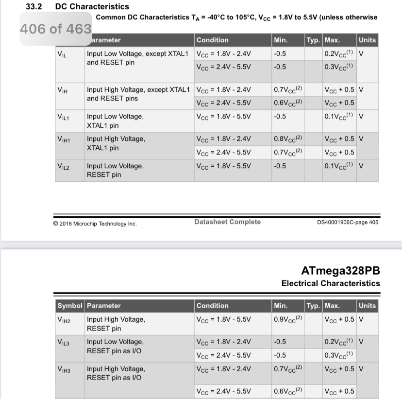
Ausschnitt aus einem Datenblatt für ATmega328PB
, except XTAL1 and RESET pins VCC = 1.8V - 2.4V 0.7VCC(2) VCC + 0.5 V VCC = 2.4V - 5.5V 0.6VCC(2) VCC + 0.5 V VIL1 Input Low Voltage, XTAL1 pin VCC = 1.8V - 5.5V -0.5 0.1VCC(1) V VIH1 Input High Voltage, XTAL1 pin VCC = 1.8V - 2.4V 0.8VCC(2) VCC + 0.5 V VCC = 2.4V - 5.5V 0.7VCC(2) VCC + 0.5 V VIL2 Input Low Voltage, RESET pin VCC = 1.8V - 5.5V -0.5 0.1VCC(1) V © 2018 Microchip Technology Inc. Datasheet Complete DS40001906C- page 405 ATmega328PB Electrical Characteristics VIH2 Input High Voltage, RESET pin VCC = 1.8V - 5.5V 0.9VCC(2
in „Lora will einfach nicht.“ · Mikrocontroller und Digitale Elektronik · · Screenshots
-
Datei
lcd.s
.L4: sbic 48-0x20,5 rjmp .L4 lds r24,4096 .L6: sbic 48-0x20,5 rjmp .L6 lds r24,4096 mov r26,r24 .L8: sbic 48-0x20,5 rjmp .L8 lds r24,4096 mov r23,r24 ldi r22,lo8(0) rjmp .L10 .L18: sbic 48-0x20,5 rjmp .L18 lds r20,4096 mov r18,r22 clr r19 ldi r24,lo8(160) ldi r25,hi8(160) mul r18,r24 movw r30,r0 mul r18,r25 add r31,r0 mul r19,r24 add r31,r0 clr r1 subi r30,lo8(-(pixel)) sbci r31,hi8(-(pixel)) add r30,r21 adc r31,__zero_reg__ st Z,r20 subi r21,lo8(-(1)) .L13: cp r21,r26 brne .L18 subi r22,lo8(-(1)) .L10: cp r22,r23 breq .L17 ldi r21,lo8(0) rjmp .L13 .L17: ret
in „Bug in WinAVR oder wieso macht der Compiler so einen Müll ?“ · Mikrocontroller und Digitale Elektronik ·
-
 Bild
Bild
Microchip Studio Debugging Ansicht
C_N1-ATMEGA128P_P40-M1_(32P40U) (Debugging) - Microchip Studio File Edit View Vassix ASF Project Build Debug Tools Window Help Advanced Mode Quick Launch (Ctrl+Q) main.c C_N1-ATMEGA128... P40-M1_(32P40U) Hex Processor
in „welcher Debugger für 8bit Controller (AVR etc.) ?“ · Mikrocontroller und Digitale Elektronik · · Screenshots

-
Datei
fat.c
############################################ { // Komische Sache: Die Schieberei hier bringt bei ATmega32 ca. 200 Byte weniger Code. // Bei ATmega644 wird der Code dadurch ca. 20 Bytes größer ! U8 temp; U32 templong; templong = cluster-2; // secPerCluster is always power of two temp = secPerCluster>>
in „AVR Studio: Großes Projekt aus mehreren kleinen erstellen“ · Mikrocontroller und Digitale Elektronik ·
-
Datei
fat.c
############################################ { // Komische Sache: Die Schieberei hier bringt bei ATmega32 ca. 200 Byte weniger Code. // Bei ATmega644 wird der Code dadurch ca. 20 Bytes größer ! U8 temp; U32 templong; templong = cluster-2; // secPerCluster is always power of two temp = secPerCluster>>
in „AVR Studio: Großes Projekt aus mehreren kleinen erstellen“ · Mikrocontroller und Digitale Elektronik ·
-
Datei
makefile.txt
--------------------------------------------------------------- 41. 42. 43. # MCU name 44. MCU = atmega8 45. 46. 47. # Processor frequency. 48. # This will define a symbol, F_CPU, in all source code files equal to the 49. # processor frequency. You can then use this symbol in your source code to 50.
in „Problem mit compilen mit headerdatei usw“ · Mikrocontroller und Digitale Elektronik ·
-
 Bild
Bild
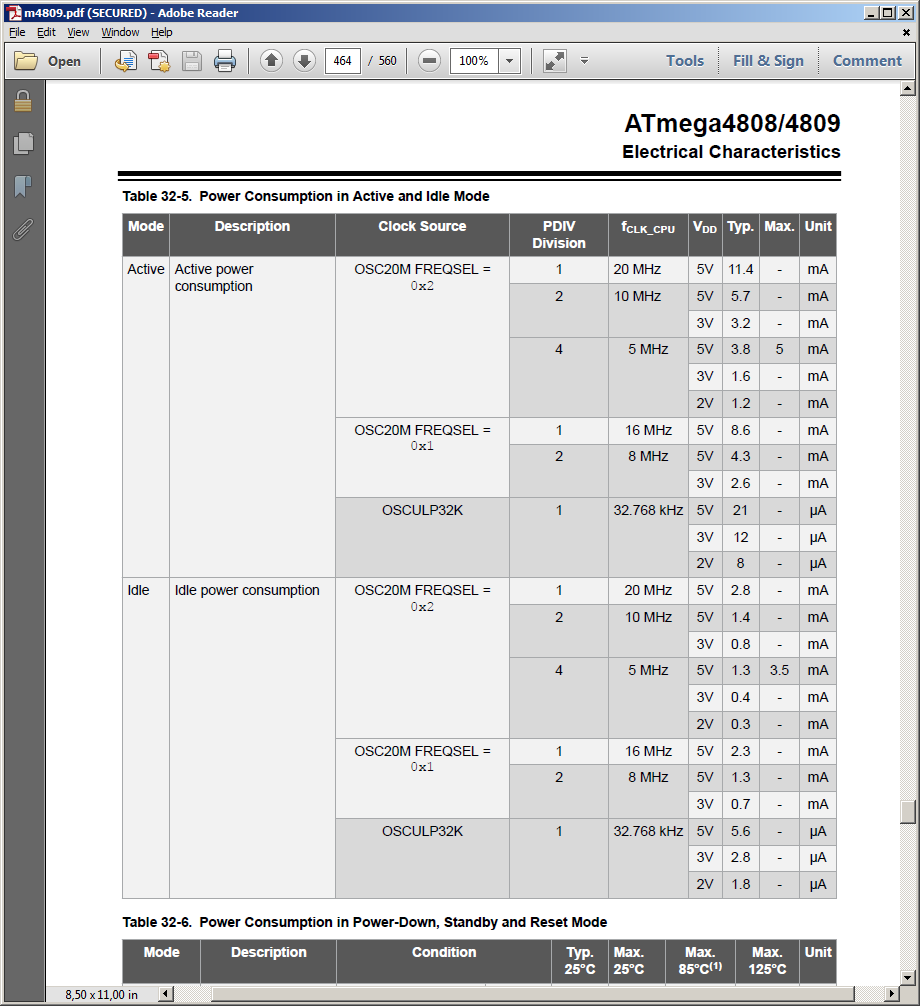
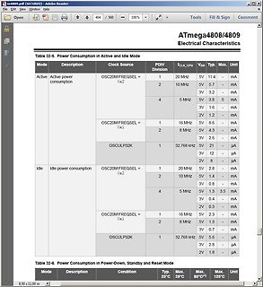
Tabelle zum Stromverbrauch eines ATmega4808/4809 Mikrocontrollers
11.4 mA 2 10 MHz 5V 5.7 mA 4 5 MHz 5V 3.2 mA 3V 1.6 mA 2V 1.2 mA OSC20M FREQSAL = 0x1 1 16 MHz 5V 8.6 mA 2 8 MHz 5V 4.3 mA 3V 2.6 mA OSCULP32K 1 32.768 kHz 5V 21 µA 3V 12 µA 2V 8 µA Idle Idle power consumption OSC20M FREQSAL = 0x2 1 20 MHz 5V 2.8 mA 2 10 MHz 5V 1.4 mA 4 5 MHz 3V 0.8 mA 5V 1.3 3.5 mA 3V 0.4 2V 0.3 mA OSC20M FREQSAL = 0x1 1 16 MHz 5V 2.3 mA 2 8 MHz 5V 1.3 mA 3V 0.7 mA OSCULP32K 1 32.768 kHz 5V 5.6 µA 3V 2.8 µA 2V 1.8 µA Table 32-6. Power Consumption in
in „AVR ATtiny Stromaufnahme“ · Mikrocontroller und Digitale Elektronik · · Screenshots
-
Datei
leuchte.cpp
/* Einfache PWM fuer alle 3x8=24 Ports eines Atmega8 Die Helligkeit die die LEDs haben sollen, steht in led_array[] und wird durch modify(); geändert. output(); Gibt sorgt dann fuer die richtige Ansteuerung. Autor: Niklas F. */ #
in „Atmega8 langsam, viel versucht = ratlos“ · Mikrocontroller und Digitale Elektronik ·
-
Datei
m8535def.inc
:ATmega8535 ;* ;* DESCRIPTION ;* When including this file in the assembly program file, all I/O register ;* names and I/O register bit names appearing in the data book can be used. ;* In addition, the six
in „include für AT Mega 8538“ · Mikrocontroller und Digitale Elektronik ·
-
Datei
m16def.inc
I L Y ;* ;* Number :AVR000 ;* File Name :"m16def.inc" ;* Title :Register/Bit Definitions for the ATmega16 ;* Date :07.09.2001 ;* Version :1.00 ;* Support telephone :+47 72 88 87 20 (ATMEL Norway) ;* Support fax :+47 72 88 87 18 (ATMEL Norway) ;* Support E-mail :avr@atmel.no ;* Target MCU :ATmega16 ;*
in „Datei für Mega16 für AVR Studio“ · Mikrocontroller und Digitale Elektronik ·
-
Datei
m8535def.txt
:ATmega8535 ;* ;* DESCRIPTION ;* When including this file in the assembly program file, all I/O register ;* names and I/O register bit names appearing in the data book can be used. ;* In addition, the six
in „Servomotor ansteuern, kein Interrupt!!!“ · Mikrocontroller und Digitale Elektronik ·
-
Datei
m16def.inc
I L Y ;* ;* Number :AVR000 ;* File Name :"m16def.inc" ;* Title :Register/Bit Definitions for the ATmega16 ;* Date :07.09.2001 ;* Version :1.00 ;* Support telephone :+47 72 88 87 20 (ATMEL Norway) ;* Support fax :+47 72 88 87 18 (ATMEL Norway) ;* Support E-mail :avr@atmel.no ;* Target MCU :ATmega16 ;*
in „avra woher die ***def.inc dateien nehmen?“ · Mikrocontroller und Digitale Elektronik ·
-
Datei
m16def.inc
I L Y ;* ;* Number :AVR000 ;* File Name :"m16def.inc" ;* Title :Register/Bit Definitions for the ATmega16 ;* Date :07.09.2001 ;* Version :1.00 ;* Support E-mail :avr@atmel.no ;* Target MCU :ATmega16 ;* ;* DESCRIPTION ;* When including this file in the assembly program file, all I/O register ;* names
in „ATMEGA16 Timer2 Assemblerproblem“ · Mikrocontroller und Digitale Elektronik ·
-
Datei
m16def.inc
I L Y ;* ;* Number :AVR000 ;* File Name :"m16def.inc" ;* Title :Register/Bit Definitions for the ATmega16 ;* Date :07.09.2001 ;* Version :1.00 ;* Support telephone :+47 72 88 87 20 (ATMEL Norway) ;* Support fax :+47 72 88 87 18 (ATMEL Norway) ;* Support E-mail :avr@atmel.no ;* Target MCU :ATmega16 ;*
in „Assembler Include-Dateien“ · Mikrocontroller und Digitale Elektronik ·
-
Datei
uart.c
debug.h" #include <avr/interrupt.h> #include <avr/io.h> #include "uart.h" #define TXQ_SIZE 256 uint8_t txq_head; volatile uint8_t txq_tail; static uint8_t txq_data[TXQ_SIZE]; #if defined (__AVR_ATmega128__) #define UCSRA UCSR0A #define UCSRB UCSR0B #define UCSRC UCSR0C #define UBRRL UBRR0L #define UBRRH
in „ATMega128-UART-empfangen&ausgeben“ · Mikrocontroller und Digitale Elektronik ·
-
Datei
AVR910-m8.txt
S8535 = 0x68 .equ m83 = 0x65 .equ m161 = 0x60 .equ m163 = 0x64 .equ m603 = 0x42 .equ m103 = 0x41 .equ m8 = 0x76 ;ATmega8 .equ m8b = 0x77 ;ATmega8 boot ;**** Revision Codes **** .equ SW_MAJOR = '2' ; Major SW revision number .equ SW_MINOR = '2' ; Minor SW revision number .equ HW_MAJOR = '1' ; Major HW revision
in „Wer wandelt ASM ---> Hex ?“ · Mikrocontroller und Digitale Elektronik ·
-
Datei
LTI_TLC5947.cpp
1 << DD_MOSI ) | ( 1 << DD_SCK ) | ( 1 << BLANK ) | ( 1 << XLAT ); // SPI-Takt = CPU-Takt / 16. ATmega16 als Busmaster. SPCR |= ( 1 << SPE ) | ( 1 << MSTR ) | ( 1 << SPR0 ); } void LTI_TLC5947::TLC5947_SetGS(uint8_t channel, uint16_t value) { channel = 24 - 1 - channel; uint16_t i = (uint16_t)channel
in „Funktionsaufruf aus C++ Klasse funkioniert nicht“ · Mikrocontroller und Digitale Elektronik ·
-
PDF
ATmega32.pdf
- 12VDC LM7805 + + + -D8 -D7 -D6 -D5 -D4 -D3 -D2 -D1 + + - + + 1N4 148 1N4 148 1N4 148 1N4 148 1N4 148 1N4 148 1N4 148 1N4 148 -C1 -C2 -C3 -C4 4,7µF 100nF 100nF 4,7µF -K8 -K7 -K6 -K5 -K4 -K3 -K2 -K1 12,5Ohm 12,5Ohm 12,5Ohm 12,5Ohm
in „ATmega32 5V Relais Ansteuerung“ · Mikrocontroller und Digitale Elektronik ·
-
Datei
lcd_ssd1306_gfx.h
_t y, uint8_t color); void lcd_drawLine(uint8_t x1, uint8_t y1, uint8_t x2, uint8_t y2, uint8_t color); void lcd_drawRect(uint8_t px1, uint8_t py1, uint8_t px2, uint8_t py2, uint8_t color); void lcd_fillRect(uint8_t px1, uint8_t py1, uint8_t px2, uint8_t py2, uint8_t color); void lcd_drawCircle(uint8_t center_x, uint8_t center_y, uint8_t radius, uint8_t color); void lcd_fillCircle(uint8_t center_x, uint8_t center_y, uint8_
in „SSD1306/1309 Library zum Darstellen von Text auf OLED Displays“ · Projekte & Code ·
-
Datei
fat.c
############################################ { // Komische Sache: Die Schieberei hier bringt bei ATmega32 ca. 200 Byte weniger Code. // Bei ATmega644 wird der Code dadurch ca. 20 Bytes größer ! U8 temp; U32 templong; templong = cluster-2; // secPerCluster is always power of two temp = secPerCluster>>
in „ATmega32 + SD-Karte (Klabunde-Lib)“ · Mikrocontroller und Digitale Elektronik ·
-
Datei
howto-compile.txt
Shows how to compile the ethernut 4.6.5 software for Arthernet. #Howto version 1.0 #tested on Kubuntu 8.04 #for a detailed instruction (and somewhat different way) http://www.ethernut.de/en/documents/debian.html may be interesting #this script expects all needed libs to be installed mkdir ethernut cd ethernut
in „AVR Ethernet Platine“ · Mikrocontroller und Digitale Elektronik ·
-
Datei
uart.h
_UART_H #define _UART_H // #define F_CPU 20000000 #define BAUD 9600l #define UBRR_VAL ((F_CPU+BAUD*8)/(BAUD*16)-1) // clever runden #if defined (__AVR_ATmega2560__) // der mega2560 hat 4 USART (0,1,2,3) // hier wird USART 4 verwendet #define UDR UDR3 #define UCSRA UCSR3A #define UDRE UDRE3 #define UCSRB
in „MMC SD library FAT16 FAT32 read write“ · Projekte & Code ·
-
PDF
Hausbus_for_everyone.pdf
. Das heißt, der ATMega befindet sich im sleep Zustand. Er wird nur geweckt, wenn er gebraucht wird. Mit einem Interrupt an der UART oder mit einem Interrupt von einem Sensor (Taster, ...). Stromversorgung Die Stromversorgung erfolgt Zentral. Zusätzlich zu den 2 Twisted Pair Leitungen vom RS485 Bus kommen noch +13,8 und GND. Die Busleitung besteht also insgesamt aus 4 Adern. RS485 <-‐> Ethernet Eine Verbindung vom RS485 Hausbus zum IP Netz ist nötige, damit man einfach und von Überall sein Haus unter Kontrolle
-
Datei
test1.c
// Anpassungen im makefile: // ATMega8 => MCU=atmega8 im makefile einstellen // lcd-routines.c in SRC = ... Zeile anhängen // #include <avr/io.h> #include <stdlib.h> #include "lcd-routines.h" #include <util/delay.h> #include <avr/eeprom.h
in „Fehler im Betrieb“ · Mikrocontroller und Digitale Elektronik ·
-
Datei
AVRGCC7.c
/* * Created: 26.03.2012 16:36:24 * Atmega32 16PU */ #include <avr/io.h> #include <avr/interrupt.h> #define F_CPU 8000000UL //CPU Takt vorgeben volatile static uint8_t posArray = 0; // Position im Array //const >> dürfen nicht verändert werden
in „Null im Array bricht Zählvorgang ab (AVR GCC)“ · Mikrocontroller und Digitale Elektronik ·
-
Datei
ad9854_dl8mby.c
============================================ * AD9854 China Modul Controll via USB_2_RS232 and * ATMega32 MC-Chip. 03.05.2014 DL8MBY * ================================================== * compile with: gcc -o ad9854_dl8mby ad9854_dl8mby.c */ #include <stdio.h> #include <stdint.h> char text1[40]; #define
-
Datei
0x00.asm
.include "m8def.inc" ;ATMega8 Include-Datei .equ CLOCK = 4000000 .equ BAUD = 19200 .equ UBRRVAL = CLOCK/(BAUD*16)-1 .def temp = r16 ;Speicherpointer xl(r26) xh(r27) ldi xh,0x00 ;0x0068 weil 8(32 später) für Einstellungen
in „0x00 über UART übertragen“ · Mikrocontroller und Digitale Elektronik ·
-
Datei
PWM_ADC.txt
PWM void my_delay(uint16_t milliseconds) { for(; milliseconds>0; milliseconds--) _delay_ms(1); } // 8-Bit PWM mit 8 verschiedenen Stufen void pwm_8_8(uint16_t delay){ int16_t tmp; #if STK500 TCCR1A = 0xC1; // inverted PWM on OC1A, 8 Bit Fast PWM-->1100 0001 #else TCCR1A = 0x81; // non-inverted PWM on
in „Probleme mit der Verbindung PWM + ADC“ · Mikrocontroller und Digitale Elektronik ·
-
PDF
Trans2_sch.pdf
T R +9V T3 U 1 1 2 1JP4 2 JP1 BC557C 3 Testsockel GND 0 1 K R 3 R11 R12 N 10K 3K3 G C ATmega8/88/168 0 0 0 K V R13 R 4 R 4 R 4 R 2 RESET 1 PC6(/RESET) PC0(ADC0) 23 10K D PC1(ADC1) 24 100n N C1 1n 22 AGND PC2(ADC2) 25 G 21 AREF PC3(ADC3) 26 C6 20 AVCC PC4(ADC4/SDA) 28 PC5(ADC5/SCL) R R R 1 8 MHz 9 1 8 3 8 5 8 Dü GND 100n PB6(XTAL1/TOSC1) R 6 R 6 R 6 L G e Q4 10 2 s C3 22p 22p PB7(XTAL2/TOSC2) PD0(RXD) 3 BC547B T 1 2 PD1(TXD) 4 C5 C4 8 PD2(INT0) 5 T1 S GND PD3(INT1) 6 3 4 IN OUT 7 VCC PD4
-
Datei
dmx_receive.c
/* This modul receives DMX512 data via * USART. * original target: ATmega8515 @8MHz * (for other devices please cahange pin & register definitions!) */ #include <inttypes.h> #include <avr/io.h> #include <avr/interrupt.h> #include <avr/signal.h> #define F_OSC 8000000 // Clock
in „USART-ISR mit mega8515“ · Mikrocontroller und Digitale Elektronik ·
-
Datei
Drehgeber_Atmega328_und_Codevision.txt
///////////////////////////////////////////////////////////////////////////////////// #define XTAL 8e6 // 8MHz #include <interrupt.h> #include <stdint.h> // this is needed for int8_t, etc. // target: ATmega328 //------------------------------------------------------------------------ #define PHASE_A
in „Drehgeber überspringt mehrere Werte“ · Mikrocontroller und Digitale Elektronik ·
-
Datei
test2.c
/* Eine 8-kanalige PWM mit verbessertem Lösungsansatz ATmega32 @ 8 MHz */ // Defines an den Controller und die Anwendung anpassen #define F_CPU 16000000L // Systemtakt in Hz #define F_PWM 100 // PWM-Frequenz in
in „Moodlight Sourcecode hilfe“ · Mikrocontroller und Digitale Elektronik ·
-
Datei
peps_avr_v12.bas
------------------------------ ' ' EPROM Simulator ' Conitec PEPS I ' ' Version 1.2 Zielplatform ATMEGA8 ' ' Intel-Hex File werden über RS232 entgegengenommen ' - RS232 9600 Bd mit RTS Handshake ' - Zeilenbuffer für 80 Zeichen ' ' Entwickelt aus PEPSLDR.ASM (C)Conitec ' 2014 Werner Römer [werner.roemer
in „Suche MOPPEL Projekt in Heft oder .PDF“ · Mikrocontroller und Digitale Elektronik ·
-
Datei
PWM_Erl__uterung.c
/*********************************************************************/ /* Eine 8-kanalige PWM mit verbessertem Lösungsansatz ATmega32 @ 16 MHz */ /*********************************************************************/ // Defines an den Controller und die Anwendung anpassen /*****
in „Problem mit der Soft-PWM“ · Mikrocontroller und Digitale Elektronik ·
-
Datei
AVRUSART29a.c
mit geringstem Zwischenschritt wirkt USART_halt nicht mehr. * * * Läuft auf dem AVR-P40 Nr4 mit Atmega16. * Der Atmega16 hat einen externen Quarz mit 7,33328 MHz. #include <avr/io.h> #include <util/twi.h> #include <stdint.h> // veraltet: #include <inttypes.h> #include <stdio.h> #include <util/delay.h
in „Wie kann man USART deaktivieren?“ · Mikrocontroller und Digitale Elektronik ·
-
 Bild
Bild
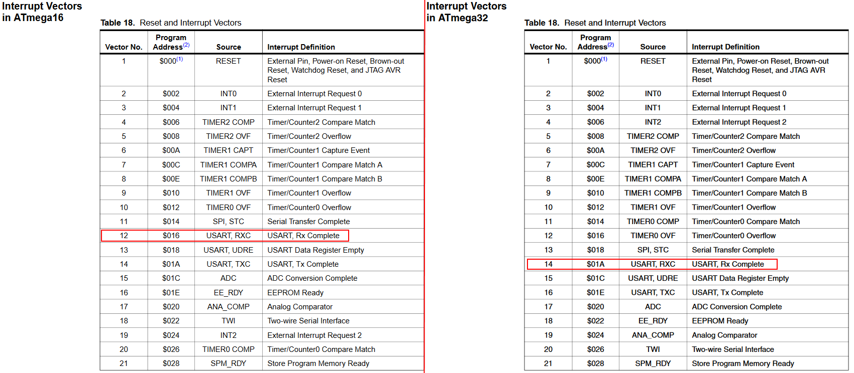
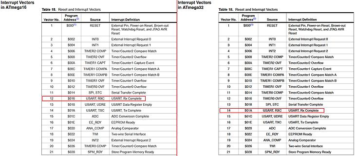
Tabelle der Interrupt-Vektoren für ATmega16 und ATmega32
Interrupt Vectors in ATmega16 Table 18. Reset and Interrupt Vectors Vector No. | Address | Source | Interrupt Definition 1 | $000 | RESET | External Pin, Power-on Reset, Brown-out Reset, Watchdog Reset, and JTAG AVR Reset 2 |
in „Hex File von Atmega16 in Atmega32 verwandeln“ · Mikrocontroller und Digitale Elektronik · · Screenshots
-
PDF
ttester-eps-converted-to.pdf
VCC VCC Ubat Reset 3 k 2 1 0 ATmega8/88/168/328 1 1 2 R 1 R 1 23 PC6(RESET) PC0(ADC0) TP1 C3 PC1(ADC1) 24 TP2 20 25 9V 100n AVCC PC2(ADC2) 26 TP3 PC3(ADC3) 21 27 2 0 4 0 6 0 AREF PC4(ADC4/SDA) 28 R 4 R 4 R 4 C1 1n PC5(ADC5/SCL) R12 22 AGND 3k3 1 8 3 8 5 8 R 6 R 6 R 6 14 9 PB0(ICP) 15 PB6(XTAL1/TOSC1) PB1(OC1A) VCC R10 22p PB2(OC1B) 16 8MHz 17 33k 10 PB3(MOSI/OC2) 10k T3 PB7(XTAL2/TOSC2) PB4(MISO) 18 22p 19 BC557C PB5(SCK) 1 7 3 GND Ubat R 3 2
-
Datei
my_eeprom.h
STS instructions. For example, see errata for ATmega64. The code below also assumes that EECR and EEDR are in the I/O space. */ uint8_t __result; __asm__ __volatile__ ( "/* START EEPROM READ CRITICAL SECTION */ \n\t" "sbi %1, %2 \n\t" "in %0, %3 \n\t
in „optimierte der EEPROM-Leseroutinen“ · Mikrocontroller und Digitale Elektronik ·
-
Datei
ADC_PWM2.txt
Ausgang void portb(void) { DDRB = 0xFF; DDRC = 0x00; } //globale Variable für die PWM uint16_t pwmtable_8[8] PROGMEM = {0,4,8,16,32,64,128,255}; #define ARRAY_SIZE(x) (sizeof(x)/sizeof(*x)) //long delays void my_delay(uint16_t milliseconds) { for(; milliseconds>0; milliseconds--) _delay_ms(1); } //8-Bit PWM in 8 Stufen void pwm_8_8(uint16_t delay) { int16_t tmp; #if STK500 TCCR1A = 0x81; //non-inverted PWM on OC1A, 8 Bit Fast PWM -->1000 0001 #else TCCR1A = 0xC1; //inverted PWM on OC1A, 8 Bit Fast PWM --> 1100
in „Probleme mit der Verbindung PWM + ADC“ · Mikrocontroller und Digitale Elektronik ·