-
PDF
3703fc.pdf
D 25V B 1 16 BAS19 MODE/SYNC VIN CIN R SET + 68µF 25k 2 15 100V R C1 SET BOOST M1 10k 3 LTC3703 14 ×2 COMP TG C Si7852DP L1 CC2 C C1 0.1µF 4.7µH 1000pF 470pF 4 13 VOUT FB SW 5V RMAX 20k 10A R2 5 I V 12 C 21.5k MAX CC
in „Längs- oder Querregler 40V 250W als Überspannungsschutz für Tiefstellsetzer“ · Analoge Elektronik und Schaltungstechnik ·
-
Datei
main.c
#if USE_OW #include "1-wire/ds18x20.h" // Variable uint16_t ow_array[MAXSENSORS]; // Speicherplatz für 1-wire Sensorwerte PROGMEM uint8_t DS18B20IDs[MAXSENSORS+1][OW_ROMCODE_SIZE] = { OW_ID_T01, // 1. DS18B20 OW_ID_T02, OW_ID_Last }; /
in „AVR für wenig Geld im LAN“ · Mikrocontroller und Digitale Elektronik ·
-
PDF
MC9S08MM128RM.pdf
Average Number AVGE AVGS[1:0] Factor (AverageNum) 0 xx 1 1 00 4 1 01 8 1 10 16 1 11 32 Table 10-19. Base Conversion Time (BCT) e Base Conversion o M Time (BCT) 8b se 17 ADCK cycles 9b diff 27 ADCK cycles 10b s.e. 20 ADCK cycles 11b diff 30 ADCK cycles 12b s.e. 20 ADCK cycles 13b diff 30 ADCK cycles 16b
in „Freescale s08mm128 und USB“ · Mikrocontroller und Digitale Elektronik ·
-
PDF
X100-LE_AB_A2A.pdf
in Ω at rated temperature N in K (T = 298 K for test condition) N T, TN= temperature in K 7000 e = base of the natural logarithm (e = 2.71828) 6000 B = B value, material specific constant of the NTC 5000 thermistor 4000 T ⋅ TN R N 3000 B = B N ⁄ T= -------⋅ ln---- T – N R T 2000 1000 00 10 20 30 40 50
in „[V] Hochleistungs-LED-Module auf Metallkernplatine“ · Markt ·
-
PDF
SM8952AC25.PDF
port 3 & external memory write 17 13 19 P3.7/#RD L/- i/o bit 7 of port 3 & external memory Read 18 14 20 XTAL2 o Crystal out 19 15 21 XTAL1 i Crystal in 20 16 22 VSS Sink Voltage, Ground 21 18 24 P2.0/A8 i/o bit 0 of port 2 & bit 8 of external memory address 22 19 25 P2.1/A9 i/o bit 1 of port 2 & bit 9
in „SM8952A Programm auslesen von RFID Reader“ · Mikrocontroller und Digitale Elektronik ·
-
PDF
SM8952AC25.pdf
port 3 & external memory write 17 13 19 P3.7/#RD L/- i/o bit 7 of port 3 & external memory Read 18 14 20 XTAL2 o Crystal out 19 15 21 XTAL1 i Crystal in 20 16 22 VSS Sink Voltage, Ground 21 18 24 P2.0/A8 i/o bit 0 of port 2 & bit 8 of external memory address 22 19 25 P2.1/A9 i/o bit 1 of port 2 & bit 9
in „Whirlpool-Steuerung Manipulieren / Fernsteuern: Welches Protokoll?“ · Mikrocontroller und Digitale Elektronik ·
-
PDF
142c38eef4c5eb392531e1bacd4aee1b.pdf
Operation Ts=+60℃,240hrs 4 Low Temperature Operation Ta=-20℃,240hrs 5 High Temperature & Humidity Operation Ta=+60℃±2℃ 90%RH 240H Power on -30℃ 30 min~+70℃ 30 6 Thermal Shock(Non-operation) After testing, cosmetic min,Change time:5 min,20 Cycles Frequency range
in „Raspberry Pi Rev A TFT Display?“ · Digitale Signalverarbeitung / DSP / Machine Learning ·
-
 Bild
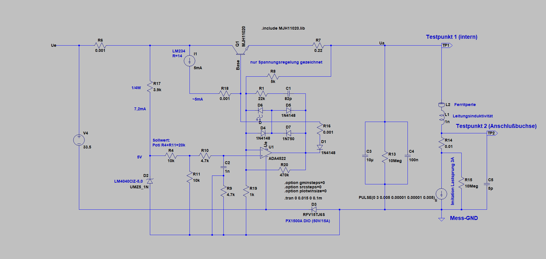
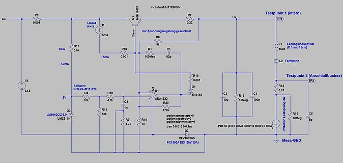
Schaltplan einer Spannungsregelung
Ue R6 0.01 LM234 R=14 I1 5mA Q1 MJH1020 Base nur Spannungsregelung gezeichnet R8 5k Ua Testpunkt 1 (intern) TP1 L2 Ferritperle L1 Leistungsinduktivitat 1n Testpunkt 2 (Anschlussbuchse) TP2 R14 0.01 R16 0.01 D1 1N4148 C3 10µ C4 10n R13 10Meg C5
in „Nebenprojekt: Analoges Labornetzteil inkl. Schaltplan und Messungen“ · Projekte & Code · · Schaltpläne
-
 Bild
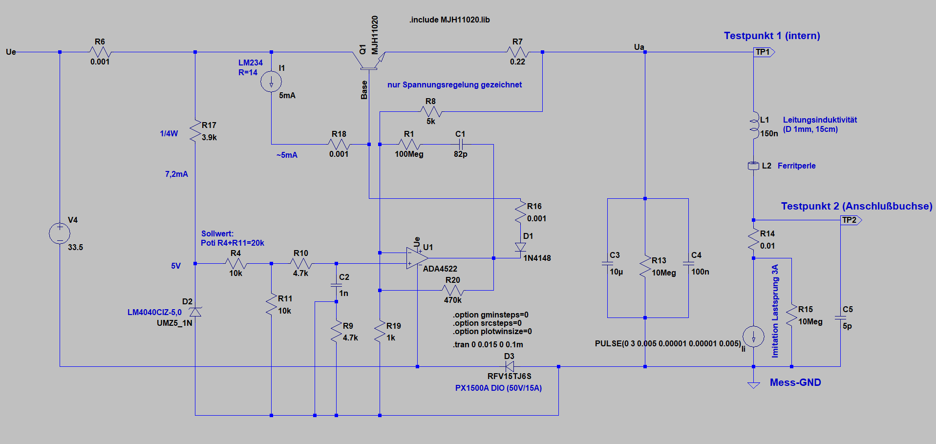
Schaltplan einer Simulation einer Spannungsregelung
Ue R6 0.01 LM234 R=14 I1 5mA Q1 MJH1020 Base nur Spannungsregelung gezeichnet R8 5k R17 3.9k R1 0.01 C1 82p Ua Testpunkt 1 (intern) TP1 L1 Leitungsinduktivität 150n (D 1mm, 15cm) R18 ~5mA 7,2mA V4 3.5 Sollwert: Poti R4+R1=20k R4 10k R10 4.7k R1 10k C2 1n D2 LM404CIZ-5.0 U1 ADA452 R20 470 .option gminsteps=0 .option srcsteps=0 .option plotwinsize=0 .option Imitation PULSE(0 3 0.005 0.01 0.01 0.05) .tran 0 0.015 0 0.1 D3 RFV15J6S R16 0.01 D1 1N4148 C3 10u R13 10Meg C4 10n TP2 Testpunkt
in „Nebenprojekt: Analoges Labornetzteil inkl. Schaltplan und Messungen“ · Projekte & Code · · Schaltpläne
-
PDF
20a14.pdf
25A Series SERIES 25A SERVO AMPLIFIERS Models: 12A8, 25A8, 20A14, 20A20 Miniature Series FEATURES: • Surface-mount technology • Small size, low cost, ease of use • DIP switch selectable: current, voltage, velocity, analog position loop • Four quadrant regenerative
in „SERVO AMPLIFIER DEFEKT!“ · Mikrocontroller und Digitale Elektronik ·
-
Datei
DTMF-MF-Teletype.BAS
'----------------------------------------------------------------------- ' DTMF-MF-Teletype.BAS ' T.Sauer 06.1.2007 ' Senden von Text als DTMF Töne mit spezieller Codierung ' Verwendung: ' Fernsteuerung von Atmel Controllern mit ' DTMF Tönen via Funk/Telefon/Akustische Kopplung ' Dieses Prgramm
in „DTMF Töne übertragen ASCII Text (zum Fernsteuern!?)“ · Projekte & Code ·
-
PDF
AD8307.pdf
VALUE = 1µF INPUT FREQUENCY = 100MHz CFO VALUE = 0.1µF –2 5 –1.0 8 - - 8 8 0 0 –3 –1.5 –80 –60 –40 –20 0 20 –80 –60 –40 –20 0 20 INPUT LEVEL (dBm) INPUT LEVEL (dBm) Figure5.LogConformancevs.InputLevel(dBm),100MHzand300MHz Figure8.LogConformancevs.CFOValuesat1kHzInputFrequency Rev. D | Page 6 of 24 AD8307
in „logarithmic detector“ · Mikrocontroller und Digitale Elektronik ·
-
PDF
RDA5851S.pdf
○ DSP Co-Processor (VoC) Bi-MAC, dual operation unit 16-bit instruction set with 32-bit extension 20 kByte + 20 kByte data RAM on 32 bits 32 kByte instruction RAM on 32 bits ○ Direct Memory Access (DMA) All size, all alignment and all source and destination possible 32-bit word pattern mode ○ Page Spy
-
PDF
MC1377.pdf
Optionally Trimable P SUFFIX PAL/NTSC Compatible PLASTIC PACKAGE CASE 738 Internal 8.2 V Regulator 20 1 DW SUFFIX 20 PLASTIC PACKAGE 1 CASE 751D (SO–20L) ORDERING INFORMATION Operating Device Temperature Range Package MC1377DW SO–20L MC1377P TA= 0⋅ to +70⋅C Plastic DIP Figure 1. Representative Block
in „Phasenverschiebung -90 bis -180° erzeugen“ · Analoge Elektronik und Schaltungstechnik ·
-
PDF
MC1377.PDF
Optionally Trimable P SUFFIX PAL/NTSC Compatible PLASTIC PACKAGE CASE 738 Internal 8.2 V Regulator 20 1 DW SUFFIX 20 PLASTIC PACKAGE 1 CASE 751D (SO–20L) ORDERING INFORMATION Operating Device Temperature Range Package MC1377DW SO–20L MC1377P TA= 0⋅ to +70⋅C Plastic DIP Figure 1. Representative Block
in „Problem beim FBAS Signal am Amiga 500“ · Analoge Elektronik und Schaltungstechnik ·
-
PDF
STM32F4-BASEbrd.pdf
1 SV1 10 V 10 SV5 1 1 4VS 2 01 1 1 0 1 6 R R8 N F SV6 M J C 7 4 X2 5 CU R9 JP7 JP15 C C 1 0 C20 C18 R10 3 e 2 4 3 1 C U1 1 U2 P A S 1 C22 C R11 J P C1 1 t J 4 6 5 7 9 D1 S c JP11 61R C C C C C 1 3 n 4 2 71R C23X1 JP5 w o 3 4 4 w 3 4 5 C C R 02R R2 1 P J X W R R R D R 81R 1 C6 C C J C26 s o 1 1 6 91R L 87 C93 R15 s D D Di C R R C . E E Em D 72C R1 C2 e L L L S 1 SV2 20 1 SV3 10 01.03.2012 18:44:54 C:\Users\SuperK\13-Eagle\1-Projekte\STM32F407Vx_Baseboard\STM32F4-BASE.brd
in „STM32F407 (100pin) Basisboard - Review bitte“ · Mikrocontroller und Digitale Elektronik ·
-
Datei
Display_OLED.bas
'Programmname: Textausgabe.bas 'Funktion: Ausgabe auf OLED-Display EA W204-XLG 'Mikrocontroller: Mega2560 'Output: LC-Display an Port A '------------------------------------------------------------------------------------ $regfile
in „OLED Display W204-XLG von electronic Assembly“ · Mikrocontroller und Digitale Elektronik ·
-
PDF
mc33151u.pdf
Cycle - R Both Drive Outputs Loaded f = 200 kHz I U TA= 25⋅C R 40 C 40 U L f = 500 kHz T P O t S t 20 f ,C 20 r t IC f = 50 kHz t r 0 0 0.1 1.0 10 0.1 1.0 10 CL, OUTPUT LOAD CAPACITANCE (nF) CL, OUTPUT LOAD CAPACITANCE (nF) Figure 13. Drive Output Rise and Fall Time Figure 14. Supply Current versus Drive
in „Mosfett-Driver Art-Kompatibel?“ · Analoge Elektronik und Schaltungstechnik ·
-
PDF
TPG051_Spec_1_3.pdf
Vcom no load PWM output voltage V 0 - V PWM CC Feed back voltage V 0.55 0.6 0.65 DC/DC operating FB Base drive current I - - 1 V output =3.0V vs. 2.3V(External) PWMD PWM Base sink current I - - 1 VPWM output =0V vs. 0.7V(External) PWMS 表單編號: 版本: 本資料為統寶光電股份有限公司之智慧財產權及機密文件,非經本公司書面授權許可,不得透露或使用本資料,亦不得複印、複製或轉變成其
in „LCD von TerAsic mit Cyclone II von Altera“ · FPGA, VHDL & Co. ·
-
PDF
datasheet__1_.pdf
www.DataSheet4U.com 10/100 Base-TX Transformer Modules Single Port 16 Pin DIL . Meets all IEEE 802.3 and ANSIX 3.263 standard including 350 uH OCL with 8mADC Bias. . Cable interface for isolation and low common mode emissions. . 16
in „Was ist ein "Lan Transformer"“ · Mikrocontroller und Digitale Elektronik ·
-
Datei
ONEWIRE-BOLT.h
//ONEWIRE-BOLT.h //ARCHIVO AUXILIAR CON LAS FUNCIONES PARA LEER LA //TEMPERATURA DEL SENSOR DS18B20 DEL SISTEMA BOLT. //USA EL PIN RA3 PARA CONECTARSE AL DS18B20 //LA FUNCION ds1820_read() REGRESA UN VALOR //DE PUNTO FLOTANTE CON LA TEMPERATURA LEIDA. //NO OLVIDE INSERTAR EL SENSOR DS18B20 EN SU BASE
in „DS18B20 Tempsensor mit PIC18F - Oszillatorprobleme?“ · Mikrocontroller und Digitale Elektronik ·
-
Datei
console_out.txt
0x0 CPU ID: 0x4 Board ID: 0x402 <9>Ethernet Mac address: 00.11.22.33.44.55 <9>Model Config length=6 Base year of RTC is 2010. ************************************************************** You didn't specify audio image address, use default instead... ***************************************************
in „Fantec Mediaplayer 3DS4600 zeigt nur noch Startbildschirm“ · Mikrocontroller und Digitale Elektronik ·
-
PDF
ADNS-2700.pdf
default: stall ProductString(xx=02) ProductString Returns USB Optical Mouse 24 03 55 00 53 00 42 00 20 00 4f 00 70 00 74 00 69 00 63 00 61 00 6c 00 20 00 4d 00 6f 00 75 00 73 00 65 00 Synopsys cmd: No Default: Accept Addressed: Accept Configured: Accept Notes: 1. A request for any other string will STALL
in „USB Maus mit USART auslesen“ · Mikrocontroller und Digitale Elektronik ·
-
Datei
lpc210x.h
****************************************************** #ifndef __LPC210x_H #define __LPC210x_H /* Base Adresses */ #define TIMER0_BASE ((pLPC_TIMER_typedef)0xE0004000) #define TIMER1_BASE ((pLPC_TIMER_typedef)0xE0008000) /* 0xE0000000 //Watchdog timer 0xE000C000 //UART0 0xE0010000 //UART1 0xE001C000
in „ARM: Absturz zur Laufzeit“ · Mikrocontroller und Digitale Elektronik ·
-
Datei
main.c
******************** * Function Name : NVIC_Configuration * Description : Configures Vector Table base location. * Input : None * Output : None * Return : None *******************************************************************************/ void NVIC_Configuration(void) { #ifdef VECT_TAB_RAM /* Set the Vector Table base location at 0x20000000 */ NVIC_SetVectorTable(NVIC_VectTab_RAM, 0x0); #else /* VECT_TAB_FLASH */ /* Set the Vector Table base location at 0x08000000 */ NVIC_SetVectorTable(NVIC_VectTab_FLASH, 0x0);
in „STM32 103RB und Probleme mit SPI1“ · Mikrocontroller und Digitale Elektronik ·
-
PDF
D2T1_-_Dissecting_a_Cloud-Connected_E-Scooter_-_Nikias_Bassen.pdf
reports • Driving statistics • Some social media stuff EXT_TEST .json ? • SameAPI calls,just different base URL account-dev.niucache.com instead ofaccount.niu.com app-api-dev.niucache.com instead ofapp-api.niu.com • App offers test account Lets check how this works Let’ s check how this works Token! JSONW
in „RS485 Signal senden Niu Sharing Roller“ · Mikrocontroller und Digitale Elektronik ·
-
PDF
MotorolaDatenCD_2000.pdf
600 6 20 –25 — 0.13 368/2 Table 2. To 225 MHz VHF AM/FM – Vertical MOSFETs For VHF military and commercial aircraft radio transmitters. Pin P out Input Power Efficiency Output Power Typical G ps(Typ)/Freq. Typical
-
PDF
inhalt.pdf
Units Test Conditions Bright Red 700 High Efficiency Red 625 λ peak Peak Wavelength Green 565 nm IF=20mA Yellow 590 Super Bright Red 660 Bright Red 45 High Efficiency Red 45 ∆λ 1/2 Spectral Line Green 30 nm IF=20mA Halfwidth Yellow 35 Super Bright Red 20 High Efficiency Red 12 Capacitance Green 45 pF
in „avr mit segmentanzeige (spezifikationen limit)“ · Mikrocontroller und Digitale Elektronik ·
-
 Bild
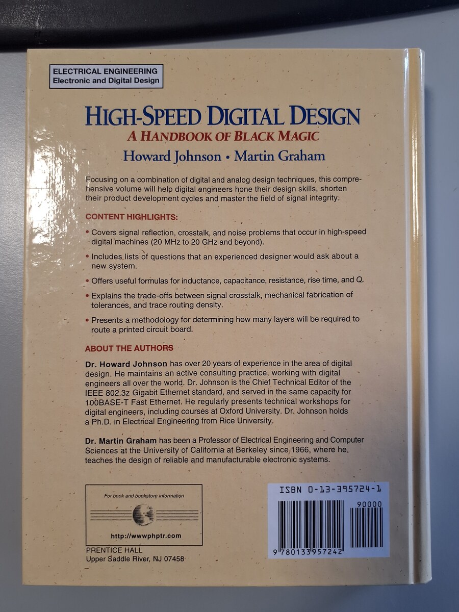
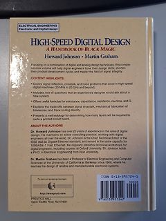
Buchcover High-Speed Digital Design
Covers signal reflection, crosstalk, and noise problems that occur in high-speed digital machines (20 MHz to 2 GHz and beyond). • Includes lists of questions that an experienced designer would ask about a new system. • Offers useful formulas for inductance, capacitance, resistance, rise time, and Q.
in „[V] High-Speed Digital Design - A Handbook of Black Magic“ · Markt · · Fotos
-
PDF
an19fc.pdf
OUT)( OUT 24 5 )() during switch “on” time, and the suggested value is L = = = 99μ H approximately 20% of the peak current rating of the VIN( )• f 24() •40 k LT1070switch(5A),orinsomecases,20%oftheaverage Example2:FlybackconverterwithV INV,V OUT=±15V inductor current. This 20%rule-of-thumb is designed
in „LT1270 dimensionieren“ · Analoge Elektronik und Schaltungstechnik ·
-
PDF
744771168_Data-DE.pdf
test conditions Wert / value Einheit / unit tol. [mm] 5,4 Induktivität / 1 kHz / 0,25V L 68,00 µH ±20% Inductance DC-Widerstand / @ 20°C R 0,096 typ. 2,9 DC-resistance DC typ. Ω DC-Widerstand / DC-resistance @ 20°C R DC max. 0,120 Ω max. 7,0 12,8 Nennstrom / ∆T=40 K IDC 1,91 A max. Rated current Sättigungsstrom
in „Probleme mit dem LM3404“ · Mikrocontroller und Digitale Elektronik ·
-
PDF
BYW02-200.pdf
versus coppPr surface under each lead.bient 100th(e-a) 80so l Printed circuit : epoxy (e=35µm) O 60 40 20 10 Scu(cm ) 0.0 0.5 1.0 1.5 2.0 2.5 3.0 3.5 4.0 4.5 5.0 4/5 SMBYW02-200 SMBKAGE MECHANICAL DATA E1 DIMENSIONS REF. Millimeters Inches D Min. Max. Min. Max. A2 0.05 0.20 0.002 0.008 b 1.95 2.20 0.077
in „Welche Diode ist das?“ · Mikrocontroller und Digitale Elektronik ·
-
PDF
CYStech_MTB09N03H8.pdf
Conditions Static BV DSS 30 - - V V GS, I D250μA VGS(th) 1.0 1.7 3.0 V V DS= V GSI D250μA G FS *1 - 20 - S V DS=5V, ID=20A GSS - - ± 100 nA V GS20 DSS - - 1 μA V DS=24V, V GS =0 - - 25 V DS=20V, V GS =0, Tj=125°C ID(ON)*1 50 - - A V DS=10V, V GS =10V - 8 9.5 m Ω V GS=10V, ID=25A RDS(ON)*1 - 15 19 m Ω
in „[S] CYStech MOSFETs“ · Markt ·
-
PDF
MB91F465DA-FujitsuMediaDevices.pdf
[R/W] IF2DTB20 [R/W] IF 2 Register 00000000 00000000 00000000 00000000 00C058 H, Reserved 00C05C H 00C060H IF2DTA20 [R/W] IF2DTA10 [R/W] 00000000 00000000 00000000 00000000 IF2DTB20 [R/W] IF2DTB10 [R/W] 00C064H 00000000
in „LCD Display / Controller eines Schweißgerätes prüfen“ · Mikrocontroller und Digitale Elektronik ·
-
PDF
EPCOS_AN_01_Principles_of_SAWR-stabilized_oscillators.pdf
discussed. An application example for a 433.92MHz transmitter for keyless entry is given. Updated: May 20, 2001as SAW Components Version: 2.1 D-81617 Munich Department: SAW CE AE PD P.O. Box 801709 http://www.epcos.com SAW Components Application: Principles of SAWR stabilized oscillators Principles of SAW-stabilized
-
Datei
stdio.h
defined(__cplusplus) */ #define BUFSIZ 512 #define _NFILE 10 struct _iobuf { char * _ptr; char * _base; int _cnt; int _bufsiz; unsigned short _flag; char _file; int _wcnt; }; typedef struct _iobuf FILE; extern FILE _iob[_NFILE]; #define stdin (&_iob[0]) #define stdout (&_iob[1]) #define stderr (&_iob
in „printf Ausgabe beim C167cr über RS232“ · Mikrocontroller und Digitale Elektronik ·
-
Datei
BootLoader.bas
---------------------------------------------------------------- ' (c) 1995-2007, MCS ' Bootloader.bas ' This sample demonstrates how you can write your own bootloader ' in BASCOM BASIC ' VERSION 2 of the BOOTLOADER. The waiting for the NAK is stretched ' further a bug was resolved for the M64/M128 that
in „Problem mit MCS Bootloader“ · Mikrocontroller und Digitale Elektronik ·
-
Datei
emac.c
PCONP |= 0x40000000; iStep = 1; return 0; break; case 1: MAC_MCFG = 0x8018; /* host clock divided by 20, no suppress preamble, no scan increment */ for ( i = 0; i < 0x40; i++ ); MAC_MCFG = 0x0018; /* Apply a reset */ /* Reset all EMAC internal modules. */ MAC_MAC1 = MAC1_RES_TX | MAC1_RES_MCS_TX | MAC1
in „STM32F207 + KS8721 (Ethernet Phy)“ · Mikrocontroller und Digitale Elektronik ·
-
Datei
hal.c
PORTD = portD; DDRB = ddrB; DDRC = ddrC; DDRD = ddrD; return; } void initTimer() { // Prescaler : 20MHz / 20000kHz TimerAufrufe = 1000 / PreScaler 8 = 250 TCCR0A = (1<<WGM01); TCCR0B = (1<<CS01); TIMSK0 = (1<<OCIE0A); OCR0A = 250; sei(); return; } void startInjection (volatile struct INJECTOR *inj,
in „C++ auf einem MC, wie geht das?“ · Mikrocontroller und Digitale Elektronik ·
-
PDF
Motortreiber_diskret.pdf
+Mot1 Stift1 D105 3 Kanal 1 SMBJ28 1 R111 PA4 LED0805-rot LED0805-rot 12.2k -Mot1 Stift1 MCL103 2 BAS40-05 Br4 T20 M21 9 9 M41 T40 2 TP1 4 G 8 8 G 4 TP2 D31 # 1 3 1 7 7 1 3 1 3 Q31 STL1550 R5 R22 D D U D R42 2 P11 1 1 1 BC850 R24 2 6 2 6 2 R44 BC850 1 1 BC850 1 Q111 end- up ~1 Q11 3 10k 1 3 S 5 2D25
in „Motoransteuerung - 24vdc / max. 500W“ · Analoge Elektronik und Schaltungstechnik ·
-
PDF
ISL6753.pdf
RESDEL OUTLL R22 1206 CT OUTLR 3.74k CR7 1206 BAT54 R4 FB1 OUTUL 4.7k U2 3 1 5% RAMP OUTUR PS2701-1P R20 2512 4 1 499 CS GND 2 R6 R9 R24 5.11k 499 C14 100k 4.7nF 2 3 2 Q11 1 R12 MJD50 20.0k CR2 3 BAT54C 1 3 1 BIAS VR2 U3 R29 R30 BZX84-C6V8 2 2 3 20.0k 20.0k 1 3 R7A, B C6 3 18.7 180pF R23 C5 0805 5% COG
in „Warum FET-Ansteuerung mit Trafo?“ · Analoge Elektronik und Schaltungstechnik ·
-
PDF
TIC246D.pdf
Repetitive peak IDRM VD = rated DRM G = 0 TC= 110°C ±2 mA off-state current Vsupply +12 V† RL = 10 Ω p(g)> 20 μs 12 50 Gate trigger Vsupply +12 V† RL= 10 Ω p(g)> 20 μs -19 -50 IGT current V = -12 V† R = 10 Ω t > 20 μs -16 -50 mA supply L p(g) Vsupply -12 V† RL= 10 Ω p(g)> 20 μs 34 V = +12 V† R = 10 Ω t > 20
in „Triac belastbarkeit“ · Mikrocontroller und Digitale Elektronik ·
-
PDF
tic246.pdf
Repetitive peak IDRM VD = rated DRM G = 0 TC= 110°C ±2 mA off-state current Vsupply +12 V† RL = 10 Ω p(g)> 20 μs 12 50 Gate trigger Vsupply +12 V† RL= 10 Ω p(g)> 20 μs -19 -50 IGT current V = -12 V† R = 10 Ω t > 20 μs -16 -50 mA supply L p(g) Vsupply -12 V† RL= 10 Ω p(g)> 20 μs 34 V = +12 V† R = 10 Ω t > 20
in „Sicherheitsfrage (220V~)“ · Analoge Elektronik und Schaltungstechnik ·
-
PDF
SN75468D.pdf
drivers (LED and gas discharge), line drivers, and logic buffers. The SN75468 has a 2700- series base resistor for each Darlington pair for operation directly with TTL or 5-V CMOS. The SN75469 has a 10.5-k series base resistor to allow its operation directly with CMOS or PMOS that use supply voltages
in „SPDIF/PCM über 3W Luxeon LED -> Treiber für MOSFET gesucht“ · Analoge Elektronik und Schaltungstechnik ·
-
PDF
Strombelastbarkeit.pdf
Platine, der Umgebung und Luft - bewegung. The current - carrying - capacitor of copper tracks on base material Example: A track 1.5 mm wide on 35 mm copper will heat to approx. 10 °C above room temperature when a 3 amp current is applied. These values may vary greatly depending on the structure of the
in „max. Strom bei 35µ Leiterbahn“ · Mikrocontroller und Digitale Elektronik ·
-
PDF
Schematic_SIMInterface_Base_v2_Sheet_1_20190912110535.pdf
7 VCC 16 A1 GPA7 28 8 R1 17 A2 1K GND 18 RESET# GPB0 1 1 BTN_9_16 330 GPB1 2 2 Header_Male_1x8 R3 20 INTA GPB2 3 3 19 INTB GPB3 4 4 U1 330 VCC GPB4 5 ARDUINO_PRO_MICRO GPB5 6 5 1 24 R4 9 7 6 2 TXO RAW 23 VCC C1 10 VDD GPB6 8 7 3 RXI GND 22 GND 330 100nF VSS GPB7 8 4 GND RESET 21 R5 5 GND VCC 20 6 2
in „AVR - Hilfe bei Schematics prüfung?“ · Mikrocontroller und Digitale Elektronik ·
-
PDF
STA413A_pin.pdf
2-3 Transistor Arrays & MOS FET Arrays With Built-in Avalanche Diode between Collector and Base Number V CEO(V) IC(A) hFE R DS(ON) Part No. Chip Package Fig. No. ofCircuits V DSS(V) ID(A) (min) max( ) STA460C 2 60 10 6 Bipolar 700 SIP10Pin 1 STA371A 2 Bipolar 2000 SIP8Pin 3 60 10 2 STA301A 4 Bipolar
in „Motor Steuergerät IC´s gesucht“ · Analoge Elektronik und Schaltungstechnik ·
-
PDF
Linear_VCO.pdf
approach is preferred. In most cases, a Colpitts oscillator is successfully used. Circuits with grounded base exhibit severe stability problems and even the Colpitts oscillator, based on its emitter circuitry, shows ocassional unwanted resonances up to 6GHz. This is due to the fact that the modern Si and SiGe
in „Leicht unterschiedliche Frequenzen stabil erzeugen“ · Analoge Elektronik und Schaltungstechnik ·
-
PDF
wuerth-doppeldrossel-744878101.pdf
test condition Induktivität (je Wicklg.) / 0,8 inductance (each wdg. 1 kHz / 0,25V L1, 2 100,0 µH ±20% DC-Widerstand (je Wicklg.) / DC-resistance (each wdg) @ 20° R DC1,2 1,400 Ω typ. 2,2 DC-Widerstand (je Wicklg.) / @ 20° R DC1,2 1,730 Ω max. DC-resistance (each wdg) 3,1 Nennstrom (je Wicklg.) / ∆T
in „Isolierter Eingang für Kontakt“ · Analoge Elektronik und Schaltungstechnik ·
-
PDF
2_gameboy.pdf
A2 10 9 A3 9 10 A4 8 11 A5 7 12 A6 6 13 A7 5 14 A8 27 15 A9 26 16 A10 23 17 A11 25 18 A12 4 19 A13 20 19 20 A14 20 21 A15 22 21 22 D0 13 1 23 D1 14 2 24 D2 15 3 25 D3 17 4 26 D4 18 5 27 D5 19 28 D6 20 29 D7 21 30 /RESET 10 31 Audio in 32 Ground 16 12 The bankswitcher. Below, I show how the ROM and the
in „(Chip8 / gameboy) Emulator für AVR AVR32“ · Mikrocontroller und Digitale Elektronik ·