-
Bild
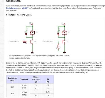
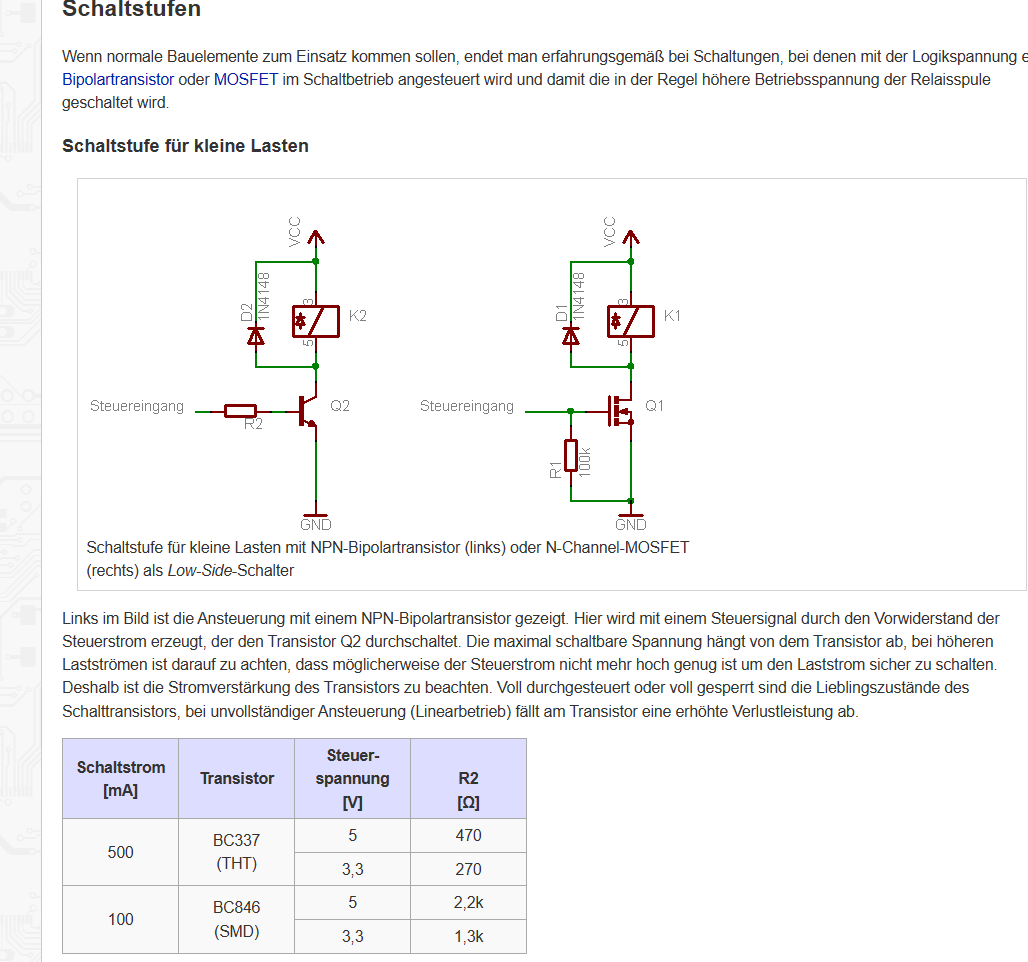
Schaltplan und Tabelle für Transistor-Schaltstufen
für kleine Lasten Schaltstufe für kleine Lasten mit NPN-Bipolartransistor (links) oder N-Channel-MOSFET (rechts) als Low-Side-Schalter VCC, D2, 1N4148, K2, Steuereingang, Q2, R2, GND, D1, 1N4148, K1, Steuereingang, Q1, R1, 100k, GND Schaltstrom [mA], Transistor, Steuerspannung [V], R2 [Ω] 500, BC337
in „basiswiderstand“ · Analoge Elektronik und Schaltungstechnik · · Screenshots
-
PDF
contrast2.pdf
Der gleiche Vorschlag ohne MOSFET, sollte auch so funktionieren, habe es aber nicht ausprobiert !!! von uC Portpin funktioniert gut mit Timer-Interrupt alle 100msec (Portpin auf High) Ref REF TLV2461 100k plus zusätzlichem Compare-Interrupt
in „Display Kontrast mit AVR Regeln“ · Mikrocontroller und Digitale Elektronik ·
-
PDF
Bilder.pdf
anderen Bauteilen kenne. PIN 1 2 Schottky-Dioden Drossel GND Output zum Gate des Input DMX Signal Mosfet NCE6020K 10 µF GND 100 nF Verbunden mit Shunt links 15kOhm Verbunden mit (Shunts sind Shunt rechts parallel geschaltet +24V = 110 mOhm) an 10 µF UnbekannterIC Gatetreiber mit Defekte Einheit (rot),
in „[suche] Ersatz für IC 34701?“ · Analoge Elektronik und Schaltungstechnik ·
-
PDF
L6206.pdf
▯▯▯▯▯▯▯▯▯▯▯▯ thermal shutdown and a non-dissipative overcurrent detection on the high-side Power MOSFETs plus a diagnostic output that can be 2UGHULQJ▯QXPEHUV▯ easily used to implement the overcurrent /▯▯▯▯1▯▯3RZHU',3▯▯▯ protection. /▯▯▯▯3'▯▯3RZHU62▯▯▯ /▯▯▯▯'▯▯62▯▯▯ February 2014 DocID7617 Rev 2 1/31
in „l6206 Datenblatt Fehler?“ · Mikrocontroller und Digitale Elektronik ·
-
PDF
IFX9201SG-DS-v01.pdf
CSN SPI chip select (low active) 10 SCK SPI clock input 11 DIS Disable. Disables the outputs (all MOSFETS off) 12 PWM Pulse width modulation input Data Sheet 4 Rev. 1.1, 2015-02-15 IFX9201SG Pin Configuration 2.3 Terms IVS DIS VS V DIS VS DIR DIR V DIS PWM PWM VDIR V PWM I I OUT1 OUT1 CSN CSN I SCK SCK
in „Keine Open Load Meldung bei ata6836c und IFX9201SG!“ · Mikrocontroller und Digitale Elektronik ·
-
Bild
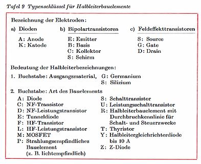
Typenschlüssel für Halbleiterbauelemente
HF-Transistor T: Thyristor L: HF-Leistungstransistor Y: Halbleitergleichrichterdiode bis 10 A M: MOSFET Z: Z-Diode P: Strahlungsempfindliches Bauelement (z. B. lichtempfindlich)
in „Was sind das für Transistoren?“ · Analoge Elektronik und Schaltungstechnik · · Diagramme
-
Bild
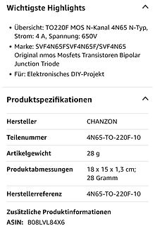
Produktspezifikationen für TO220F MOS N-Kanal Transistor
MOS N-Kanal 4N65 N-Typ, Strom: 4 A, Spannung: 650V Marke: SVF4N65FSVF4N65F/SVF4N65 Original nmos Mosfets Transistoren Bipolar Junction Triode Für: Elektronisches DIY-Projekt Produktspezifikationen Hersteller: CHANZON Teilenummer: 4N65-TO-220F-10 Artikelgewicht: 28 g Produktabmessungen: 18 x 15 x 1,3
in „Bauteilbezeichnung“ · Analoge Elektronik und Schaltungstechnik · · Screenshots
-
PDF
contrast.pdf
Ref 100k P-Kanal MOSFET Ref von uC Portpin FDC658P funktioniert gut mit Timer-Interrupt alle 100msec (Portpin auf High) Ref 100k plus zusätzlichem Compare-Interrupt REF Ref TLV2461 2 1 5 3 (Portpin auf Low) 4 3 1 6 5 4 fuer
in „Display Kontrast mit AVR Regeln“ · Mikrocontroller und Digitale Elektronik ·
-
PDF
4088fb.pdf
components are neces- 1xand5xmodes. sary.However,ifmoreconductanceisneeded,anexternal P-channel MOSFET transistor can be added from BAT to 3.3V Always-On Supply VOUT .TheGATEpinoftheLTC4088drivesthegateofthe P-channel MOSFET transistor for automatic ideal diode The LTC4088 includes an ultralow quiescent current low control. The source of the external P-channel MOSFET dropout regulator that is always powered. This LDO can beusedtoprovidepowertoasystempushbuttoncontrol- should be connected to V OUT and the drain should be ler or standby microcontroller. Designed
in „[EAGLE Anfänger] Package finden oder herstellen“ · Platinen ·
-
Bild
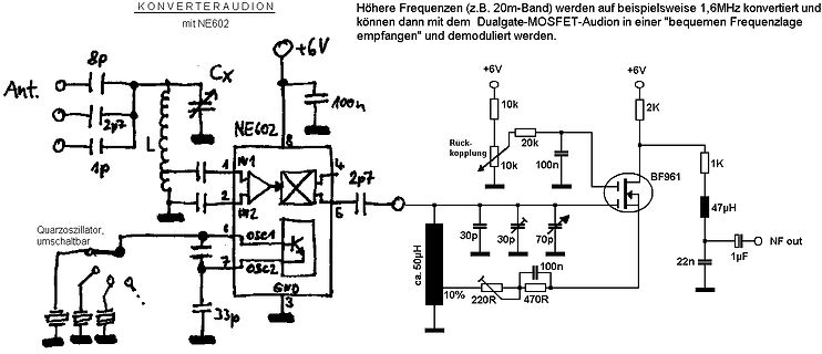
Handgezeichneter Schaltplan eines Audio-Konverters
Frequenzen (z.B. 20m-Band) werden auf beispielsweise 1,6MHz konvertiert und können dann mit dem Dualgate-MOSFET-Audion in einer "bequemen Frequenzlage" empfangen und demoduliert werden. Ant. 8p 2p7 L Cx NE602 1 4 2 5 6V 10k 20k 10k 100n 2p7 BF961 1K 47uH 22n 1uF NF out 30p 30p 70p 100n ca. 50uH 10% 220R 470R
in „Gibt es diskrete Schaltungstechniken, die erst in jüngerer Zeit entwickelt wurden?“ · Offtopic · · Schaltpläne
-
PDF
Benutzte_Teile_Bewegungsmelder.pdf
Spindeltrimmer IN =2V-24V / 2A/10Wmax OUT = 2 V-28V, PIR HC-SR501, Photoresistor RES-PH-GL55 LDR, IRF3708 Mosfet 30V 62A 87W 0,012R 854130, Widerstand 593-0 MOX 5,6 Ohm 2Watt Metaloxid 5,6R 2w 0414 081376, LED 1Watt 120Im High Power 350mA 6500k
in „Bewegungsmelder PIR Ausgang“ · Mikrocontroller und Digitale Elektronik ·
-
Bild
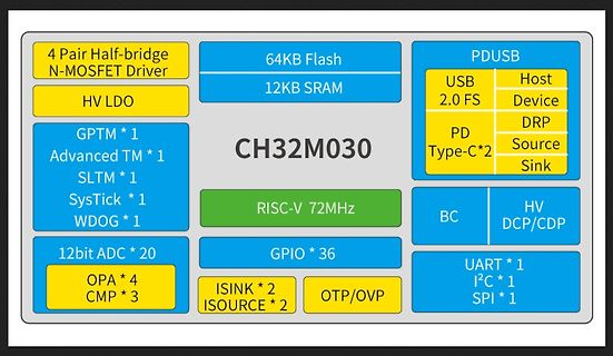
Blockschaltbild des Mikrocontrollers CH32M030
4 Pair Half-bridge N-MOSFET Driver, HV LDO, GPTM * 1, Advanced TM * 1, SLTM * 1, SysTick * 1, WDOG * 1, 12bit ADC * 20, OPA * 4, CMP * 3, 64KB Flash, 12KB SRAM, CH32M030, RISC-V 72MHz, GPIO * 36, ISINK * 2, ISOURCE * 2, OTP/OVP
in „ESP32-E22 offiziell, neuer Mikrocontroller von WCH, Raspberry Pi-Tethering uvam“ · Mikrocontroller und Digitale Elektronik · · Diagramme
-
PDF
LYT4321E.pdf
at a fixed line input voltage. resistor (R11) via the low R DS(ON)of the MOSFET Q3 thereby maintaining high system efficiency. The gate of Q3 is biased To limit the output voltage at no-load an output overvoltage through the divider of R4, R5, and R6 and filtered by C13. protection
in „PI LYTSwitch, wofuer diese Diode“ · Analoge Elektronik und Schaltungstechnik ·
-
Bild
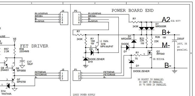
Schaltplan eines FET-Treibers und Power Boards
10UF Q6 MPS650 Q8 2N4401 Q7 MPS750 D14 1N4744A J5 FETSENS FETDRIVE B- P1 FETSENS FETDRIVE B- 35 MOSFET IN PARALLEL 33 CAPS IN PARALLEL 35 75 OHMS IN PARALLEL LOGIC POWER SUPPLY
in „Curtis 1205 Reihenschlussmotor“ · Analoge Elektronik und Schaltungstechnik · · Schaltpläne
-
Bild
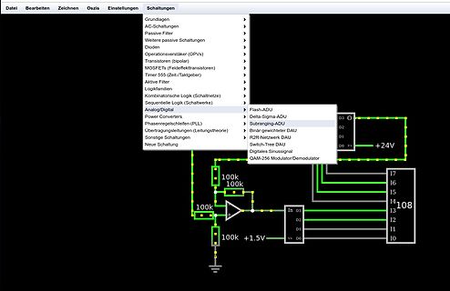
Schaltplan mit Menüauswahl
Passive Filter Weitere passive Schaltungen Dioden Operationsverstärker (OPVs) Transistoren (bipolar) MOSFETs (Feldeffekttransistoren) Timer 555 (Zeit-Taktgeber) Aktive Filter Logikfamilien Kombinatorische Logik (Schaltetze) Sequentielle Logik (Schaltwerke) Analog/Digital Power Converters Delta-Sigma-ADU
in „Subranging DAC“ · Mikrocontroller und Digitale Elektronik · · Screenshots
-
Bild
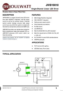
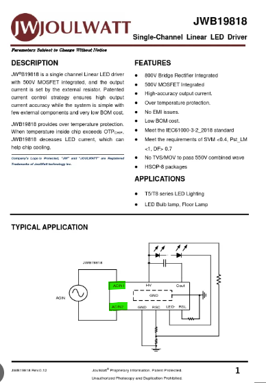
Datenblatt eines Single-Channel Linear LED Drivers
Driver Parameters Subject to Change Without Notice FEATURES 800V Bridge Rectifier Integrated 500V MOSFET Integrated High-accuracy output current. Over temperature protection. No EMI issues. Low BOM cost. Meet the IEC61000-3-2_2018 standard Meet the requirements of SVM <0.4, Pst_LM > 0.7 APPLICATIONS T5
in „LED-Lampe Ikea - L/R Parallelschaltung?“ · Analoge Elektronik und Schaltungstechnik · · Screenshots
-
PDF
Div.Teile.pdf
Dioden, 95% unbenutzt- alle zusammen- 2,00€ Div.Transistoren 95% unbenutzt- pro Schublade 2,00€ 20x MosFet N-Kanal 55Volt 30A IRLZ34NPBF 2,00€ Diverse IC, unbenutzt-zusammen- 10,00€ Ich separiere die Schubladen nicht noch einmal. Preise für Versand je nach Menge und aufwand, aber immer so günstig wie es
in „(V) Diverse Teile“ · Markt ·
-
Bild
Datenblatt des MP1495 Synchronous Step Down Converters
Converter DESCRIPTION Wide 4.5V-16V Operating Input Range 80mΩ/30mΩ Low R_ON(INT) Internal Power MOSFETs High-Efficiency Synchronance Mode Operation Fixed 500kHz Switching Frequency Synchronizes to a 200kHz to 2MHz External Clock AAM Power-Save Mode Internal Soft-Start OCP Protection and Hiccup Thermal
in „Fritzbox 7590 fiept“ · PC Hard- und Software · · Screenshots
-
Bild
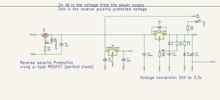
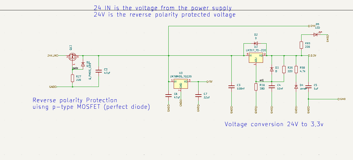
Schaltplan mit Verpolungsschutz und Spannungsregelung
24V D5 LED R93 220 D2 D 3.3V R30 4.7k D4 zener C5 1uf GND Reverse polarity Protection uisng p-type MOSFET (perfect diode) Voltage conversion 24V to 3,3v
in „PCA9685 I2C Probleme, SCL hängt“ · Mikrocontroller und Digitale Elektronik · · Schaltpläne
-
Bild
Screenshot der Webseite mikrocontroller.net
Komponenten, LED, Logische Verknüpfungen, Logik, Mikrocontroller, Modellierung analoger Schaltungen, MOSFET, Multiplexer, Operationsverstärker, Grundlagen, PWM, Präzision, Relais, Schaltung, Schwingung, Schwingung, Schwingung, Schwing
in „Spam im Wiki“ · www.mikrocontroller.net · · Screenshots
-
Bild
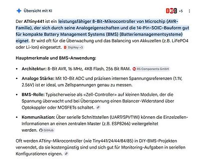
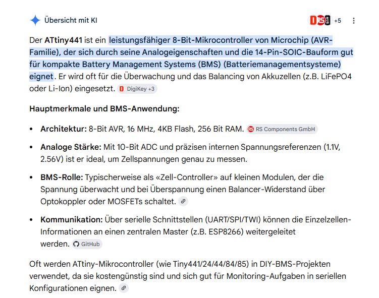
Text über ATtiny441 Mikrocontroller und BMS-Anwendung
der die Spannung überwacht und bei Überspannung einen Balancer-Widerstand über Optokoppler oder MOSFETs schaltet. Kommunikation: Über serielle Schnittstellen (UART/SPI/TWI) können die Einzelzellen-Informationen an einen zentralen Master (z.B. ESP8266) weitergeleitet werden. Oft werden ATtiny-Mikrocontroller
in „alternativ Akku zum verbauten??“ · Analoge Elektronik und Schaltungstechnik · · Screenshots
-
Bild
Google Suchergebnisse für CCA7001 Datasheet
ccu2... PDF CCU2350 Datasheet 31.10.2019 — The monolithic integrated bipolar circuit CCU2350 is a MOSFET or IGBT-control circuit which works on the principle of pulse width modulation ...
in „Datenblatt Cypress cca7001“ · Mikrocontroller und Digitale Elektronik · · Screenshots
-
PDF
DIV-642.pdf
Drain). Der Ausgangsstrom darf maximal 25mA betragen. Bei größeren Strömen empfiehlt sich ein n-ch-MOSFET. Das Gate wird dabei direkt mit Vout verbunden und über 100k an V+. Der Source liegt an GND. Der Betriebsspannungsbereich des ICL7665 beträgt 1,6 bis 16V. Der Eigenstromverbrauch des ICL7665 liegt
in „ICL7665 und Li-Ion Unterspannungsschutz“ · Analoge Elektronik und Schaltungstechnik ·
-
PDF
Lueftersteuerung-v1.pdf
REF M 3 D9# R O M1 D8 N U D7 o n A0 D6# i u A1 Zwischenkreiskondensator r C1 D5# A 2 Logiclevel Mosfet A2 Z1 D4 A3 1 D3#/INT1 3 A4/SDA D2/INT0 A5/SCL D1 (TX) Pull-Down-Widerstand R1 D0 (RX) D N G GND USB Buchse 2 GND USB Buchse 1 Buchse 1 und Buchse 2 befinden sich an einer Powerbank, somit gleiches
in „Arduino und 5V Lüfter (PWM) an einer Stromversorgung“ · Mikrocontroller und Digitale Elektronik ·
-
PDF
Schaltung2.pdf
Motoranschlüssen z.B. 15R und einem NT mit Festspannung. Das erleichtert Messungen. DieWahl der Mosfet‘s ist unkritisch. Sie sollten nur die Spannung und Leistung schalten können. IRF540 / IRF9540 R2-R6 = 470R R12 - R16 =<1K R18 - R21 = 10K Hühnerfutter habe ich nicht eingezeichnet. DieTLP250 trennen
in „Spielerei mit einem 5-Phasen-Schrittmotor“ · Projekte & Code ·
-
Bild
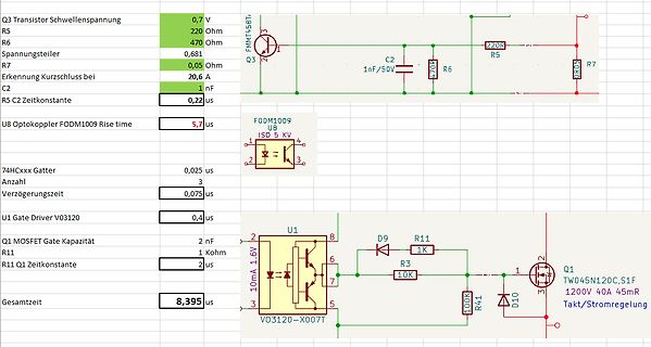
Schaltplan mit Bauteilberechnungen und Zeitkonstanten
5 KV 74HCxxx Gatter 0,025 us Anzahl 3 Verzögerungszeit 0,075 us U1 Gate Driver V03120 0,4 us Q1 MOSFET Gate Kapazität 2 nF R11 1 Kohm R11 Q1 Zeitkonstante 2 us Gesamtzeit 8,395 us U1 D9 R11 1K R3 10K 100K R41 D10 Q1 TW045N120C, S1F 1200V 40A 45mR Takt/Stromregelung VO3120-X007T 10mA 1,6V
in „MOSFET TW045N120C Kurzschlussschutz maximale Zeit ?“ · Analoge Elektronik und Schaltungstechnik · · Screenshots
-
Datei
buz21.txt
*n-MOSFET*100V 21A 85mOhm*Add_in_Line .SUBCKT BUZ21_IN 1 2 3 LS 5 2 7N LD 95 3 5N RG 4 11 5.5M RS 5 76 52M D21 76 95 DREV .MODEL DREV D CJO=1.2N RS=20M TT=50N IS=300P BV=100 M21 86 11 76 96 MBUZ .MODEL MBUZ
in „Wandler Kühlschrank: Rätselhafter Schaltplan.“ · Analoge Elektronik und Schaltungstechnik ·
-
Bild
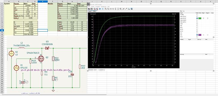
Screenshot einer LTspice Simulation mit Schaltplan und Kurvenverlauf
System Param. Wert Unit MOSFET Param. Wert Unit RDSon 0,16 Ω @ 150° Vin 16 V UGS 10V M 33,68 W tf 2,70E-08s if 8,00E-09s M 100 W tf 6,70E-08s if 2,52E-09s Ripple 0,1% 0,163 P(DC) 3,57 W P(sw) 4,38 W P(out) 18,62 W P(tot Coss 2,2E
in „12V auf 325V Boost Converter mit LT3757“ · Analoge Elektronik und Schaltungstechnik · · Screenshots
-
Bild
Schaltplan mit ATtiny13A, Spannungsregler und Motorsteuerung
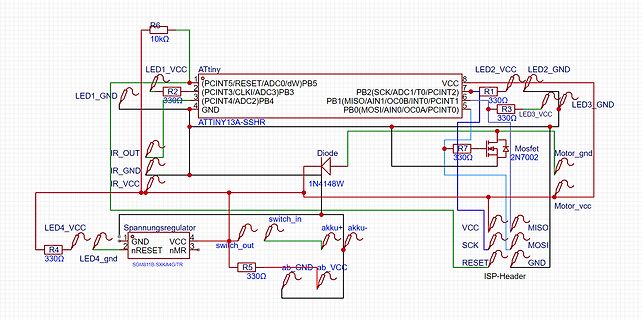
INT0/PCINT1)PB1, (MOSI/AIN0/OC0A/PCINT0)PB0, R3 330Ω, LED3_VCC, LED3_GND, R7 330Ω, Diode 1N4148W, Mosfet 2N7002, Motor_gnd, Motor_vcc, VCC, MISO, SCK, MOSI, RESET, GND, ISP-Header
in „(AVR) Attiny85 PWM“ · Mikrocontroller und Digitale Elektronik · · Schaltpläne
-
PDF
batt_train.pdf
ca. 20V/µS danach Symetrischer Lade- / begrenzt durch max U von den Entladevorgang der Spule mit Mosfets IRLR2905 auf 55V sehr schnellem Strompuls am Verweildauer auf Maxwert und Ausschaltpunkt. Gesamtdauer danach Resonanzschwinger; Puls ist ca. 50µS asymetrisch. Ladekennlinie IU0/U mit Pulsladetechnik
in „Battery Vitalizer“ · Mikrocontroller und Digitale Elektronik ·
-
Bild
Bauteilliste oder BOM Tabelle
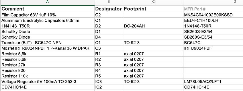
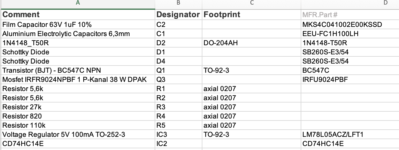
Diode D1 SB260S-E3/54 Schottky Diode D4 SB260S-E3/54 Transistor (BJT) - BC547 NPN Q1 TO-92-3 BC547C Mosfet IRFR9024NPBF 1 P-Kanal 38 W DPAK Q3 IRFU9024PBF Resistor 5,6k R1 axial 0207 Resistor 5,6k R2 axial 0207 Resistor 27k R3 axial 0207 Resistor 820 R4 axial 0207 Resistor 110k R5 axial 0207 Voltage Regulator
in „CD74HC14M Schmitt-Trigger Schaltung funktioniert nicht“ · Mikrocontroller und Digitale Elektronik · · Screenshots
-
PDF
kp2124dp.pdf
KP212X 多模式、恒流恒压原边控制功率开关 主要特点 产品描述 集成 650V MOSFET KP212X是一款高性能原边控制器,可提供高精度 支持反激和降压型拓扑应用 恒压和恒流输出性能,尤其适合于小功率离线式充 反激原边控制(SEL 管脚悬空) 电器应用中。同时,KP212X也支持准谐振降压型 准谐振降压控制 (SEL= GND) LED恒流、恒压输出应用,仅需将SEL管脚短接到 ±4%恒流、恒压精度 GND管脚即可。 待机功耗<70mW 多模式原边控制方式
-
PDF
DS_FT232R.pdf
off power during the USB suspend mode. Figure 6.3 shows an example of using a discrete P-Channel MOSFET to control the power to external logic. A suitable device to do this is an International Rectifier (www.irf.com) IRLML6402, or equivalent. It is recommended that a “soft start” circuit consisting of a 1kΩ series resistor and a 0.1µF capacitor is used to limit the current surge when the MOSFET turns on. Without the soft start circuit it is possible that the transient power surge, caused when the MOSFET switches on, will reset the FT232R or the USB host/hub controller. The soft start circuit
in „Power via USB - Entstörung“ · Mikrocontroller und Digitale Elektronik ·
-
PDF
DS_FT230X.pdf
CBUS0, CBUS1, CBUS2, CBUS3 can be used to control power to external logic P-Channel logic level MOSFET switch. Enable the interface pull-down option when using the PWREN# in this way. TXLED# CBUS0, CBUS1, CBUS2, CBUS3 Transmit data LED drive – pulses low when transmitting data via USB. See Section 7.5
in „FT230X-S kaufen“ · Markt ·
-
PDF
schemazi.pdf
1 2 3 4 MOSFET Selbsthaltung 1. Buck/Boost Stufe (Ausgang: 5V) 2. Buck/Boost Stufe (Ausgang: 3.3V) A Q3 A L1 L2 4 Inductor 1, 2, 5, 6 Inductor 10mH R6 10mH Versorgung µC Q1 R1 10k Q2 R3 Solarzelle (0-5.5V) 460K 3
in „überwachung der spannung mit mosfet“ · Analoge Elektronik und Schaltungstechnik ·
-
PDF
UDN2981.pdf
-50 8 – – X – – 2580 80 8 – – X – – 2983 80 8 X X X – – 5890 -80 8 – – X – – 2588 -500 6 1 – – – MOSFET X 2525 and 2535 6 2 – – – MOSFET X 2535 and 2536 -4000 60 4 – – X – – 2944 * Current is maximum specified test condition, voltage is maximum rating. See specification for sustaining voltage limits
in „Treiber ICs (Datenblatt verstehen)“ · Mikrocontroller und Digitale Elektronik ·
-
PDF
2981.pdf
-50 8 – – X – – 2580 80 8 – – X – – 2983 80 8 X X X – – 5890 -80 8 – – X – – 2588 -500 6 1 – – – MOSFET X 2525 and 2535 6 2 – – – MOSFET X 2535 and 2536 -4000 60 4 – – X – – 2944 * Current is maximum specified test condition, voltage is maximum rating. See specification for sustaining voltage limits
in „100mm 7 Segment Anzeige“ · Mikrocontroller und Digitale Elektronik ·
-
PDF
auirs2123.pdf
AUIRS2123S, AUIRS2124S Description The AUIRS2123S/AUIRS2124S are high voltage, high speed power MOSFET and IGBT drivers. Proprietary HVIC and latch immune CMOS technologies enable ruggedized monolithic construction. The logic input is compatible with standard CMOS outputs. The output drivers feature
in „High-Side Treiber Baustein“ · Analoge Elektronik und Schaltungstechnik ·
-
Datei
Bosch_Athlet_DIY_240416.ino
0, 0, 0, 0, HOST=1, SHDN=0 ->switch to host-mode I2C_8Bit_writeToModule(0x10, 1, 0b00000110); //MOSFETs CHG=1, DSG=1 ->manually switch on mosfets again //measure current for charge and brush analogReference(DEFAULT); // Vref=3.3 V delay(20); //stabilize voltages Serial.println("----- start of cyclic
in „Bosch Athlet 25,2 V Akku 7 Stück Tauschen“ · Analoge Elektronik und Schaltungstechnik ·
-
PDF
US6236191.pdf
ofthepresentinvention,controlsWitch104is thisstate,VINsprovideddirectlytotherecti?er106making ann-channelMOSFET having asource,drainandgate.The 15 recti?er106 forWardbiased.As controlsWitch104isturned sWitchingofthecontrolsWitch104 i scontrolledby appli f,a lcurrenti spassedthroughforWardrecti?er106,.Thus, cation
in „Der magnetische Verstärker“ · Analoge Elektronik und Schaltungstechnik ·
-
PDF
p75nf75.pdf
STP75NF75 - STP75NF75FP 2 N-channel 75V - 0.0095Ω- 80A - TO-220 - TO-220FP - D PAK STripFET™ II Power MOSFET General features Type V R I DSS DS(on) D STB75NF75 75V <0.011Ω 80A (1) (1) 3 3 STP75NF75 75V <0.011Ω 80A 1 2 1 2 STP75NF75FP 75V <0.011Ω 80A (1) TO-220 TO-220FP 1. Current limited by package ■ Exceptional dv/dt capability ■ 100% avalanche tested 1 3 D²PAK Description This Power MOSFET series realized with STMicroelectronics unique STripFET™ process has specifically been designed to minimize input Internal schematic diagram capacitance and gate charge. It is therefore suitable as
in „Unbekanntes Bauteil im Akkuschrauber“ · Analoge Elektronik und Schaltungstechnik ·
-
PDF
029-02463-1-UDN2981A.pdf
-50 8 – – X – – 2580 80 8 – – X – – 2983 80 8 X X X – – 5890 -80 8 – – X – – 2588 -500 6 1 – – – MOSFET X 2525 and 2535 6 2 – – – MOSFET X 2535 and 2536 -4000 60 4 – – X – – 2944 * Current is maximum specified test condition, voltage is maximum rating. See specification for sustaining voltage limits
in „ULN2003 Soll Spannung Schalten“ · Mikrocontroller und Digitale Elektronik ·
-
PDF
STB10NK60Z.pdf
STP10NK60Z/FP STW10NK60Z N-CHANNEL 600V-0.65Ω-10A - TO220/FP-D²/I²PAK-TO-247 Zener-Protected SuperMESH™ MOSFET General features Package Type VDSS R DS(on) D Pw STB10NK60Z 600 V <0.75 Ω 10 A 115 STB10NK60Z-1 600 V <0.75 Ω 10 A 115 23 23 3 STP10NK60ZFP 600 V <0.75 Ω 10 A 35 1 1 12 TO-220 TO-220FP STP10NK60Z 600
in „Ersatz für STB10NK60Z“ · Mikrocontroller und Digitale Elektronik ·
-
PDF
NTMFS4C09N.pdf
NTMFS4C09N Power MOSFET 30 V, 52 A, Single N−Channel, SO−8 FL Features • Low R DS(on)to Minimize Conduction Losses • Low Capacitance to Minimize Driver Losses www.onsemi.com • Optimized Gate Charge to Minimize Switching Losses
in „Kontrolle Eagle Schaltplan“ · Mikrocontroller und Digitale Elektronik ·
-
Bild
Bauteilliste einer Elektronikkomponente
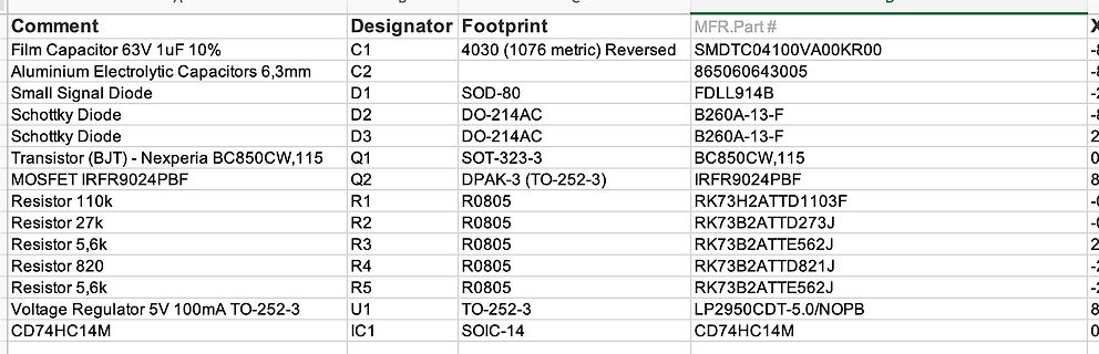
Schottky Diode D3 DO-214AC B260A-13-F Transistor (BJT) - Nexperia BC850CW,115 Q1 SOT-323-3 BC850CW,115 MOSFET IRFR9024PBF Q2 DPAK-3 (TO-252-3) IRFR9024PBF Resistor 110k R1 R0805 RK73H2ATTD1103F Resistor 27k R2 R0805 RK73B2ATTD273J Resistor 5,6k R3 R0805 RK73B2ATTE562J Resistor 820 R4 R0805 RK73B2ATTD821J Resistor
in „CD74HC14M Schmitt-Trigger Schaltung funktioniert nicht“ · Mikrocontroller und Digitale Elektronik · · Screenshots
-
Bild
Schaltplan eines Schaltreglers
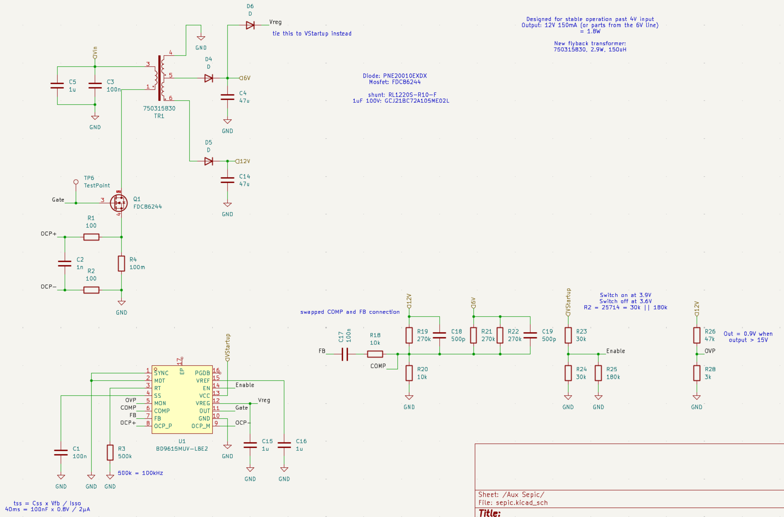
parts from the 6V line) = 1.8W New flyback transformer: 750315830, 2.9W, 15uH Diode: PNE20010EDX Mosfet: FDC8624 shunt: RL2205-R10-F 1uF 100V GCJ21BC7A10MS02L C5 1u C3 100n 750315830 TR1 D4 0 +06V C4 47u D5 D -12V C14 47u Q1 FDC8624 R1 100 Gate DCP+ C2 1n R2 100 DCP- R4 100m GND swapped COMP and FB connection
in „BD9615 (flyback) startet nicht zuverlässig“ · Analoge Elektronik und Schaltungstechnik · · Schaltpläne
-
PDF
pico-datasheet_1_.pdf
Modulation mode, which, at light loads, saves considerable power by only turning on the switching MOSFETs occasionally to keep the output capacitor topped up. Setting PS high forces the regulator into Pulse Width Modulation (PWM) mode. PWM mode forces the SMPS to switch continuously, which reduces the
in „Raspberry Pi Pico PIO (JESUS)“ · Mikrocontroller und Digitale Elektronik ·
-
Bild
LTspice Simulationsfehlermeldung
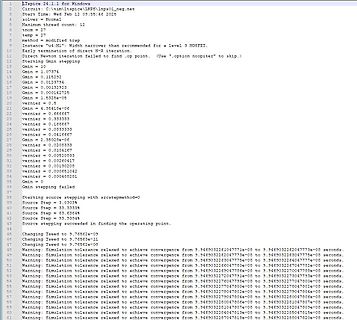
temp = 27 method = modified trap Instance "U4:M1" Width narrower than recommended for a level 3 MOSFET. Early termination failed to find .op point. (Use ".op noopiter" to skip.) Starting Gmin stepping Gmin = 10 Gmin = 0.13734 Gmin = 0.115292 Gmin = 0.0123794 Gmin = 0.0013253 Gmin = 0.00034275 Gmin =
in „LTSpice 24, Simulation blockiert“ · Analoge Elektronik und Schaltungstechnik · · Screenshots
-
PDF
Spannungsversorgung.pdf
Spannungsversorgung F1 NET-IO / 10V IN OUT 800mA ADJ C1 C2 IC1 C3 B1 µA7810 4700µF 100nA 100nA TR1 B500C1000 Mosfet / 12V 1 8 2 GND_1 GND_1 I 7S Transistor / 5V P 6 1 IN OUT IN OUT 4 5S ADJ C7 ADJ C4 C5 C6 IC2 IC5 EL60/25,5 215 B2 LM2940CT12 100nA LM2940CT5 100nA 4700µF 100nA m 0 F 8 B500C1000 0 GND_2 GND_2 3 2
in „Festspannungsregler reihenschaltung“ · Mikrocontroller und Digitale Elektronik ·
-
PDF
Spannungsversorgung.pdf
Spannungsversorgung F1 NET-IO / 10V IN OUT 800mA ADJ C1 C2 IC1 C3 B1 µA7810 4700µF 100nA 100nA TR1 B500C1000 Mosfet / 12V 1 8 2 GND_1 GND_1 I 7S Transistor / 5V P 6 1 IN OUT IN OUT 4 5S ADJ C7 ADJ C4 C5 C6 IC2 IC5 EL60/25,5 215 B2 LM2940CT12 100nA LM2940CT5 100nA 4700µF 100nA m 0 F 8 B500C1000 0 GND_2 GND_2 3 2
in „evtl. EMV Probleme in meiner Schaltung?“ · Mikrocontroller und Digitale Elektronik ·