-
PDF
elv.pdf
Eingangsgrößen an Pin 1 und Pin 2 miteinander und steuertüberseinenanPin9miteinerR/C-Kombination(R 16, PWM-Schaltregler C 27)beschaltetenAusgangdenintegriertenKomparatorund Das eigentliche Schaltnetzteil arbeitet als sekundär getak- somit das PWM-Ausgangssignal (Puls-Pause-Verhältnis). teter PWM-Schaltregler
in „Problem mit ELV Netzteil Bausatz PPS 5630“ · Mikrocontroller und Digitale Elektronik ·
-
Datei
pWM.txt
** ; ; Einlesen eines Analog-Wertes und Umrechnen in eine 8-Bit Zahl ; -------> Ausgeben als 8-Bit PWM ; -------> Ausgeben als 10-Bit PWM ; ;************************************************************************************************** .device AT90S8535 .include "8535def.inc" ;*******************
-
Datei
test1.c
/* * PWM_Schaltnetzteil_mit_Display.c * * Created: 21.06.2013 12:54:14 * Author: Phil */ #define F_CPU 8000000UL #include <avr/io.h> #include <util/delay.h> #include <stdlib.h> #include <avr/interrupt.h> #include
in „Subtrahieren funktioniert nicht wie es soll.“ · Mikrocontroller und Digitale Elektronik ·
-
PDF
RCDE-48_p5.pdf
Series Specifications (measured @ Ta= 25°C, nom. Vin and 15 LEDs (15*3V=45V) unless otherwise stated) PWM DIMMING AND ON/OFF CTRL (leave open if not used - do not tie to +Vin) Parameter Condition Value low line, DC-DC OFF 0VDC to 0.3VDC Input Voltage Limits high line, DC-DC ON 3VDC to 12VDC Dimming Voltage
in „Verständnisfrage Datenblätter LED-Treiber“ · Mikrocontroller und Digitale Elektronik ·
-
PDF
Abdel-Rahman_Osama_A_200705_PhD.pdf
switch suffers from a high voltage stress that is proportional to the load range. Compared with ZVS- PWM converter, zero-voltage-transition PWM (ZVT-PWM) converters [10, 12] are more 5 desirable since soft switching is achieved without increasing switch voltage and current stress. By adding an auxiliary
in „Welche Schaltfrequenz bei Step-Down EMV-günstig?“ · Analoge Elektronik und Schaltungstechnik ·
-
Datei
Beispiel.c
6250; // Interrupt alle 0,1sec PORTD |= (1<<PD6); // Pin als Eingang (Impulse Drehzahl aufnehmen) // PWM-Signal über Timer 4, Ausgang C TCCR4A = (1<<WGM41) | (1<<COM4C1); //PWM Mode 14 TCCR4B = (1<<WGM42) | (1<<WGM43) | (1<<CS41); //PWM Mode 14 und Prescaler 8 ICR4 = 40000; //PWM Frequenz 50Hz (50Hz=16MHz
in „String Ausgabe löst Reset aus“ · Mikrocontroller und Digitale Elektronik ·
-
Datei
log.txt
Word 0024 36 COUNTER1 Word 004C 76 TIMER1 Word 004C 76 CAPTURE1 Word 0046 70 COMPARE1A Word 004A 74 PWM1A Word 004A 74 PWM1B Word 0048 72 COMPARE1B Word 0048 72 ERR Bit 0006 6 X Byte 0061 97 Y Byte 0062 98 -------------------------------------------------------------------------------- Constant Value
in „GLCD funktioniert nicht!“ · Mikrocontroller und Digitale Elektronik ·
-
Datei
MasterService.c
->newData = true; master_state = STATE_WAIT_FOR_PWM; sprintf(buf,"POT: %3d",buf[1]); //device[0].lastData[0]); lcd_gotoxy(0,6); lcd_puts(buf); lcd_display(); } void slaveTempState(void) { unsigned char buf[5]; buf[0] = 0x04; bTimeOut = false; ptrDevice
in „RS485 von ms - immer noch Einschaltprobleme“ · Mikrocontroller und Digitale Elektronik ·
-
Datei
Pwm_Abstimmung_f_r_Pollin_Radio1.bas
' Hardware Pwm Abstimmung für das Pollin Tunermodul $regfile = "m32def.dat" $crystal = 1000000 Dim A As Integer 'Variable für Abstimmschritte bei Stoppsignal Dim B As Integer Config Pind.5 = Output 'Pwm out Config
in „PLL per Software“ · Mikrocontroller und Digitale Elektronik ·
-
Datei
Pwm_Abstimmung_Pollin_Radio1.bas
' Hardware Pwm Abstimmung für das Pollin Tunermodul $regfile = "m32def.dat" $crystal = 8000000 Dim A As Integer 'Variable für Abstimmschritte bei Stoppsignal Dim B As Integer Config Pind.5 = Output 'Pwm out Config
in „PLL per Software“ · Mikrocontroller und Digitale Elektronik ·
-
PDF
ds-mb86r01-jade-rev1-4.pdf
optional) SPI_SCK O - D PD L Serial clock (optional) SPI_SS O PN D PD L Slave select (optional) 7.2.11. PWM related pin Analog Status of pin Pin name I/O Polarity /Digital Type after reset Explanation PWM_O0 O - D PD (*1) L PWM out 0 (optional) PWM_O1 O - D PD (*1) L PWM out 1 (optional) *1: Only PWM pin
in „Bild im Bild in der Instumententafel Range Rover“ · Mikrocontroller und Digitale Elektronik ·
-
PDF
esp_wroom_32_datasheet_en.pdf
www.espressif.com 3.5 Peripheral Interface Description 3 FUNCTIONAL DESCRIPTION Interface Signal Pin Function PWM0_OUT0 ~2 PWM1_OUT_IN0 ~2 Three channels of 16-bit timers generate PWM0_FLT_IN0 ~2 PWM1_FLT_IN0 ~2 PWM waveforms; each has a pair of Motor PWM Any GPIO output signals. Three fault detection PWM0_CAP_IN0 ~2 signals. Three even capture signals. Three PWM1_CAP_IN0 ~2 sync signals. PWM0_SYNC_IN0 ~2 PWM1_SYNC_IN0 ~2 LED PWM ledc_hs_sig_ou~7 Any GPIO 16 independent channels @80MHz ledc_ls_sig_o~70 clock/RTC CLK. Duty accuracy: 16bits. U0RXD_in U0CTS_in
-
Datei
main.c
TCCR0A = 0; TCCR0B = (1<<CS02) | ((1<<CS00)); TIMSK0 = (1<<TOIE0); /** Use Timer1 for first three PWM generation * Connect OC1A (PORTB.PIN5) * Connect OC1B (PORTB.PIN6) * Connect OC1C (PORTB.PIN7) * 10-bit fast PWM Mode * Prescaler clk/8 --> ~974 Hz */ TCCR1A = (1<<COM1A1) | (1<<COM1B1) | (1<<COM1C1
in „ADC trigger source wirkungslos“ · Mikrocontroller und Digitale Elektronik ·
-
Datei
PWM_PA0_Uvergleich-IRQ4-239ms.asm
;ausgangsspannungsregelung nach stepdown ;pwm an atmega16 für 3,906 khz ;bei 4mhz taktfrequenz ;mit timer0 im fast pwm mode, 8 bit aufloesung ;pwm-signal liegt auf pb3 oc0 ;13.2.12 .include "m16def.inc" ;.def v_panel = r14 ;Messwert PV-Spannung
in „Hilfe Ladereglung Atmega16 Assembler“ · Mikrocontroller und Digitale Elektronik ·
-
Datei
PWM_PA0_Uvergleich-IVT2-239ms.asm
;ausgangsspannungsregelung nach stepdown ;pwm an atmega16 für 3,906 khz ;bei 4mhz taktfrequenz ;mit timer0 im fast pwm mode, 8 bit aufloesung ;pwm-signal liegt auf pb3 oc0 ;13.2.12 .include "m16def.inc" ;.def v_panel = r14 ;Messwert PV-Spannung
in „Hilfe Ladereglung Atmega16 Assembler“ · Mikrocontroller und Digitale Elektronik ·
-
Datei
code.txt
"); Serial.print(force1_real); Serial.print(" Fist2: "); Serial.print(force2_real); Serial.print(" PWM-vrgb: "); Serial.print(duty_cycle_set); Serial.print(" ctrl_PWM1: "); Serial.print(duty_cycle_controlled1); Serial.print(" ctrl_PWM2: "); Serial.print(duty_cycle_controlled2); Serial.print(" c_helpM1
in „Zuckende DC-Motoren bei Ansteuerung mit H-Brücke/PWM und Arduino UNO“ · Mikrocontroller und Digitale Elektronik ·
-
Datei
FastPWM-Mode_15_Code_Fehler.ino
zurueck. // Danach bleibt der SM fuer ca. 1,5 Sekunde stehen und das Spiel wiederholt sich. // Im FastPWM-Mode 15 wird eine maximale Frequenz von ca. x kHz erreicht. // //#include "Define.h" #define SM_RICHTUNG_DDR DDRK #define SM_RICHTUNG_PORT PORTK #define SM_RICHTUNG_PIN PINK #define SM_RICHTUNG ( 1<
in „Bitte um Hilfe bei der Programmierung von AVR8-Mikrocontrollern in C“ · Mikrocontroller und Digitale Elektronik ·
-
Datei
FastPWM-Mode_15_Code_Alles.ino
zurueck. // Danach bleibt der SM fuer ca. 1,5 Sekunde stehen und das Spiel wiederholt sich. // Im FastPWM-Mode 15 wird eine maximale Frequenz von ca. x kHz erreicht. // //#include "Define.h" #define SM_RICHTUNG_DDR DDRK #define SM_RICHTUNG_PORT PORTK #define SM_RICHTUNG_PIN PINK #define SM_RICHTUNG ( 1<
in „Fragen zu schrittmotor Treiber“ · Mikrocontroller und Digitale Elektronik ·
-
PDF
CRPowtech.pdf
SOT23-5 PT1203 2A, 24V, 350KHz Synchron-Bock DC/DC-Wandler SOP-8 Die PT1101 Hohe Leistungsfähigkeit PWM/PFM Buck DC/DC Konverter-Controller PWM/PFM Step-Down DC/DC Controller SOT23-5 PT1102 Buck DC/DC-Wandler (Eingebauter MOSFET) SOP-8 PT1109 1.5A, 24V, 380Khz Buck DC/DC-Wandler SOP-8 Linearer Regulierungsregler
in „Was ist das?“ · Analoge Elektronik und Schaltungstechnik ·
-
PDF
Control_Loop_Design_SLUP098__TI.pdf
equivalent circuit. Fig. 4 is the operating conditions. With peak current mode Bode gain plot of the PWM/power circuit, the control, slope compensation corrects this problem (and reduces the loop gain). This problem exists in current amplifier, and the overall current loop gain. Conditions: any switched
in „SG3524 bleibende Regelabweichung“ · Analoge Elektronik und Schaltungstechnik ·
-
PDF
2C-SDK-Espressif_IoT_SDK_Programming_Guide_v0.9.5_revised.pdf
write Return: null 89 / 95 Espressif Systems February 9, 2015 ESP8266EX SDK Programming Guide 5.4.pwm 4 PWM outputs are supported, more details in pwm.h. 5.4.1. pwm_init Function: initialize pwm function, including gpio, frequency, and duty cycle Function definition: void pwm_init(uint16 freq, uint8 *duty) Input parameters: uint16 freq——pwm’s frequency; uint8 *duty——duty cycle of each output Return: null 5.4.2. pwm_start Function: start PWM. This function need to be called after every pwm config changing. Prototype: Void pwm_start (void
in „ESP8266 hängt bei gleichzeitigem senden/empfangen“ · Mikrocontroller und Digitale Elektronik ·
-
PDF
2C-SDK-Espressif_IoT_SDK_Programming_Guide_v0.9.5.pdf
write Return: null 88 / 94 Espressif Systems January 23, 2015 ESP8266EX SDK Programming Guide 5.4.pwm 4 PWM outputs are supported, more details in pwm.h. 5.4.1. pwm_init Function: initialize pwm function, including gpio, frequency, and duty cycle Function definition: void pwm_init(uint16 freq, uint8 *duty) Input parameters: uint16 freq——pwm’s frequency; uint8 *duty——duty cycle of each output Return: null 5.4.2. pwm_start Function: start PWM. This function need to be called after every pwm config changing. Prototype: Void pwm_start (void
in „Wlan2Serial Modul für 5 euro“ · Mikrocontroller und Digitale Elektronik ·
-
Datei
Pwm_Abstimmung_f_r_Pollin_Radio.bas
' Hardware Pwm Abstimmung für das Pollin Tunermodul $regfile = "m32def.dat" $crystal = 1000000 Dim A As Byte 'Variable für Abstimmschritte bei Stoppsignal Dim C As Bit Dim D As Bit $crystal = 8000000 Config Pind.5
in „PWM Versuche mit Bascom“ · Mikrocontroller und Digitale Elektronik ·
-
Datei
lok_tn15.asm
Compare ;geändert von Hannes Lux am 05.12.08: ;deaktiviert: ; ldi TEMPI,0b01101011 ;Timer/Counter1 PWM ;hinzugefügt: ldi TEMPI,$60+fpwm ;Timer1 im PWM-Mode vorwärts mit Fahr-Vorteiler ;Sinn: ;Möglichkeit der Anpassung der PWM-Frequenz an die Eigenschaften des Motors ;Ende... out TCCR1,TEMPI ;Ausgang
in „DCC Decoder“ · Projekte & Code ·
-
Datei
test.txt
won't // work there sei(); 1c2: 78 94 sei // on the ATmega168, timer 0 is also used for fast hardware pwm // (using phase-correct PWM would mean that timer 0 overflowed half as often // resulting in different millis() behavior on the ATmega8 and ATmega168) #if defined(TCCR0A) && defined(WGM01) sbi(TCCR0A
in „Arduino Compiler Speicherverwaltung“ · Mikrocontroller und Digitale Elektronik ·
-
PDF
AVR-ASM_Tutorial.pdf
Obergrenze zu erreichen, eingeschaltet ist. Dabei gibt es aber verwirrenderweise verschiedeneArten der PWM: • Fast PWM • Phasen-korrekte PWM • Phasen- und Frequenzkorrekte PWM Für die Details zu jedem PWM-Modus sei auf das Datenblatt verwiesen. Fast PWM Die Fast PWM gibt es beim Mega8 mit mehreren unterschiedlichen
in „AVR-Tutorial als PDF“ · Offtopic ·
-
Datei
PWMCapladung.txt
// Konstanten für pwmCapladung const I_BATT_SOLL = 630; // entspricht 10 A const U_CAP_VOLL = 908; // entspricht 40 V const TN_CAP = 6.5; const KR_CAP = 0.053; thread pwmCapladung { // Prioritätsvergabe run 32; // Variablendefinition
in „Superkondensator mit PWM laden (Contoller C-Control II)“ · Mikrocontroller und Digitale Elektronik ·
-
 Bild
Bild
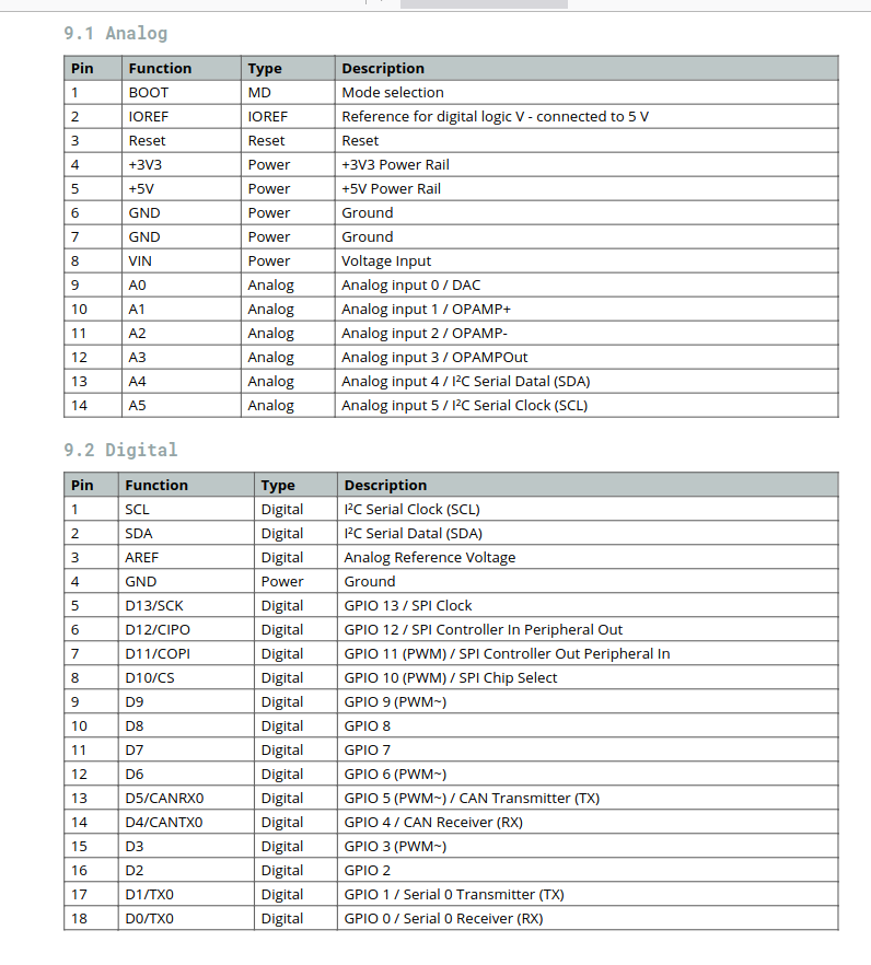
Tabellen der Pinbelegungen für Analog und Digital
SPI Clock 6 D12/COPI Digital GPIO 12 / SPI Controller In Peripheral Out 7 D11/COPI Digital GPIO 11 (PWM~) / SPI Controller Out Peripheral In 8 D10/CS Digital GPIO 10 / SPI Chip Select 9 D9 Digital GPIO 9 (PWM~) 10 D8 Digital GPIO 8 11 D7 Digital GPIO 7 12 D6 Digital GPIO 6 (PWM~) 13 D5/CANRX0 Digital GPIO 5 (PWM~) / CAN Transmitter (TX) 14 D4/CANTX0 Digital GPIO 4 / CAN Receiver (RX) 15 D3 Digital GPIO 3 (PWM~) 16 D2 Digital GPIO 2 17 D1/TX0 Digital GPIO 1 / Serial 0 Transmitter (TX) 18 D0/TX0 Digital GPIO
in „Arduino Uno R4 im Handel erhältlich“ · Mikrocontroller und Digitale Elektronik · · Screenshots
-
PDF
LPC2129EB_REVB.pdf
bit code execution at ● 2x 32 Timer with: maximum clock rate. 4x Input Capture / Output Compare ● 6x PWM Due to its low power consumption, various 32-bit ● Watchdog Timer timers, 4-channel 10-bit ADC, 2 advanced CAN ● Real Time Clock channels, 6 PWM channels and 46 GPIO lines ● -40 to +85°C Temperature
in „Einsteigerboard LPC2119(29/94)“ · Mikrocontroller und Digitale Elektronik ·
-
PDF
M500_Askoll__No_Variations__2018-12-02.PDF
EMUC3/ASCL1/RP6/CN24/RBPIU016PO REL_AYC 1k8 Vcc PU3 INT0/RP7/CN23/RBPIU017 R LAY J2 PR P8 PU0 GND TCK/PWM2H1/SCL1/RP8/CN22/RB8 18 P TX T X POHALL2L2 OUT TDO/PWM2L1/SDA1/RP9/CN21/RB9I2018P RX R X PORRESET\TPIJ01 1 VCC Hall (C11) B PGED2/EMUD2/TDI/PWM1H3/RP10/CN16/RB10I2221POH33 VCC PIJ02 2 P0 B PGEC2/EMUC2/TMS/PWM1L3/RP11/CN15/RB11I2322POL33 PIJ03 3 P9 C7 U4 PWM1H2/RP12/CN14/RB12PI2423POH22 TEMP PIJ04 4 CR9 P0 1 PWM1L2/RP13/CN13/RB13PIU024POL22 P OMCU_P33PIJ05 5 1k8 PU0 Vcc PWM1H1/RP14/CN12/RB14PIU025POH11 P
in „RX und TX Schaltung beim Askoll M505“ · Analoge Elektronik und Schaltungstechnik ·
-
Datei
VeluxSender2.ino
================================= // PWM-Ausgang deaktivieren // ============================================================ inline void pwmOutputDisable() { TCCR2A &= ~(1 << COM2B1); TCCR2A &= ~(1 << COM2B0); PORTD &= ~(1 << PD3); } // =
in „Velux WLC 100 durch Kleinsteuerung ersetzen“ · Haus & Smart Home ·
-
Datei
breadboard.c
////////////////////////////// ISR(TIMER2_COMP_vect){ // IRQ every 100us static unsigned char countPWM = 0; static unsigned int countSERVO = 0; static unsigned int countLED = 0; static unsigned int countDISPLAY= 0; countSERVO++; countLED++; countDISPLAY++; // PWM for servo if(countPWM>servopos) PORTC &= ~(1<<3); else PORTC |=(1<<3); if(countPWM<200) countPWM++; else countPWM =0; // counter for autoSERVO if((servostatus == AUTOSERVO) && (countSERVO >= 10000)){ countSERVO = 0; autoservoflag = TRUE; } // counter for LED if(!LEDoff && (countLED
in „Fragen zum timer interrupt“ · Mikrocontroller und Digitale Elektronik ·
-
PDF
SCH_CP_JR_ARM7_USB_LPC2148_1_OF_3.pdf
ONLY +3V3 +VUSB +VUSB +VUSB D LPC2138/LPC2148 D 16 19 USB LINK 560 P1.16 12 P1.16/TRACEPKT0 P0.0/TXD0/PWM1 21 P0.0 P1.17 8 P1.17/TRACEPKT1 P0.1/RXD0/PWM3/EINT0 22 P0.1 P0.31 2 P1.18 4 P1.18/TRACEPKT2 P0.2/SCL0/CAP0.0 26 P0.2 K 2 P1.19 48 P1.19/TRACEPKT3 P0.3/SDA0/MAT0.0/EINT1 27 P0.3 1 P1.20 44 P1.20/TRACESYNC
in „ARM-USB-OCD mit Eclipse“ · Mikrocontroller und Digitale Elektronik ·
-
PDF
ETT_2148.pdf
ONLY +3V3 +VUSB +VUSB +VUSB D LPC2138/LPC2148 D 16 19 USB LINK 560 P1.16 12 P1.16/TRACEPKT0 P0.0/TXD0/PWM1 21 P0.0 P1.17 8 P1.17/TRACEPKT1 P0.1/RXD0/PWM3/EINT0 22 P0.1 P0.31 2 P1.18 4 P1.18/TRACEPKT2 P0.2/SCL0/CAP0.0 26 P0.2 K 2 P1.19 48 P1.19/TRACEPKT3 P0.3/SDA0/MAT0.0/EINT1 27 P0.3 1 P1.20 44 P1.20/TRACESYNC
in „Einstieg in die ARM Welt“ · Mikrocontroller und Digitale Elektronik ·
-
Datei
ATTiny24_QTouch-V-2.txt
längerer Berührung des Sensors wird gedimmt, wechselweise von Max --> Min (= AUS) --> Max ' - 8-Bit PWM -- einstellbar in 8er Schritten ' ' Verwendung in der Praxis: ' - Die Platine mit Sensor (es geht auch eine Lachkarte mit abgesetztem Sensor) ist in einem Kunststoffgehäuse untergebracht ' - Stromversorgung
in „LED Dimmer mit Touch Sensor“ · Mikrocontroller und Digitale Elektronik ·
-
PDF
Vergleich.pdf
control and - 16-bit advanced-control timer, with dead zone control and emergency brake; can offer PWM complementary output for emergency brake; can offer PWM complementary output for emergency brake; can offer PWM complementary output for motor control motor control - 16-bit general-purpose timer, provide
in „CH32V006 und CH32V007 von WCH“ · Mikrocontroller und Digitale Elektronik ·
-
PDF
avr450.pdf
until the status is changed in the global status variable. The real-time clock is started when the PWM is started, and is also stopped when the PWM is stopped, i.e. when the battery voltage is measured. This ensures that only the time when the battery is charged is taken into account. On the other hand
-
Datei
Transistortester.h
TEXT = "Schalte aus"; const unsigned char F_GEN_str[] MEM2_TEXT = "f-Generator"; const unsigned char PWM_10bit_str[] MEM2_TEXT = "10-bit PWM"; const unsigned char RotaryEncoder_str[] MEM2_TEXT = "Impulsdrehgeber"; const unsigned char TURN_str[] MEM2_TEXT = "drehen!"; const unsigned char FULLCHECK_str[]
-
Datei
Eisenbahn_Tiny45.c
void my_delay(uint16_t milliseconds) { for(; milliseconds>0; milliseconds--) _delay_ms(1); } void pwm_init(){ // Timer0, Clear OC0B on compare Match. Mode 3: Fast PWM TCCR0A = (1<<COM0A1)|(0<<COM0A0)|(1<<WGM01)|(1<<WGM00); // 64 prescaler TCCR0B = (1<<CS01)|(1<<CS00); } int main(void) { DDRB = 0xFF; //PB0 (OC0A) ist PWM output pwm_init(); //PWM initialisieren int16_t temp; int16_t on_time=50; //Zeitkonstanten für die Pulsgeschwindigkeit int16_t rise_time=30; int16_t fall_time=100; int16_t stop_time=30; while (1) {
in „ATtiny45 10bit-PWM“ · Mikrocontroller und Digitale Elektronik ·
-
Datei
Linearitaet.bas
default use 10 for the SW stack $framesize = 40 ' default use 40 for the frame space Dim A As Byte '*****PWM einrichten Print "PWM einrichten" Print "Wenn fertig, N drücken" Config Pinb.1 = Output Config Timer1 = Pwm , Pwm = 8 , Compare A Pwm = Clear Up , Prescale = 1 'Timer 1 einrichten: 8bit Modus Do A =
in „Problem mit AD-Wandler im Atmega8“ · Mikrocontroller und Digitale Elektronik ·
-
Datei
lego.c
* // // function prototypes // //************************************************************ void PwmOn (void); void PwmOff (void); //************************************************************ // // User Functions // //************************************************************ /* Zeitmessung: Die
in „Problem: Mega48 Input Capture mit WinAVR“ · Mikrocontroller und Digitale Elektronik ·
-
Datei
Wegmessung3.bas
X_wert As Byte Dim Y_wert As Byte Dim Aufloesung(2) As Byte Dim Motion As Byte Dim Text As String * 10 'PWM defininieren Config Pinb.1 = Output Config Pinb.2 = Output Config Timer1 = Pwm , Pwm = 8 , Compare A Pwm = Clear Up , Compare B Pwm = Clear Up , Prescale = 8 'Timer1 mit Pulsweitenmodulation mit einer
in „Ansteuern eines Agilent Chip über das SPI Protokoll“ · Mikrocontroller und Digitale Elektronik ·
-
Datei
main.c
; sConfigOC.OCNIdleState = TIM_OCNIDLESTATE_RESET; if (HAL_TIM_PWM_ConfigChannel(&htim1, &sConfigOC, TIM_CHANNEL_1) != HAL_OK) { Error_Handler(); } if (HAL_TIM_PWM_ConfigChannel(&htim1, &sConfigOC, TIM_CHANNEL_2) != HAL_OK) { Error_Handler(); } if (HAL_TIM_PWM_ConfigChannel(&htim1, &sConfigOC, TIM_CHANNEL_3) != HAL_OK) { Error_Handler(); } sConfigOC.OCMode = TIM_OCMODE_PWM2; sConfigOC.Pulse = (((PWM_PERIOD_CYCLES) / 2) - (HTMIN)); if (HAL_TIM_PWM_ConfigChannel(&htim1, &sConfigOC, TIM_CHANNEL_4) != HAL_OK) { Error_Handler(); } sBreakDeadTimeConfig.OffStateRunMode = TIM_OSSR_ENABLE
in „Problem mit STM32F103 und RAM-Größe“ · Mikrocontroller und Digitale Elektronik ·
-
Datei
05_RC_PWM_Echo_V2.asm
-------------------------- ; Projektbeschreibung und Anschlussbelegung des Mikrokontrollers ; ; RC PWM lesen 8 Bit Timer 0 und 2 ; RC PWM Signal erzeugen" 16 Bit Timer 1" ;------------------------------------------------------------------------------ ; ATmega168 ; 16 MHz (externer) Takt, Teiler = 1 (
in „Atmel ATMega168 - PCINT8 und PCINT18“ · Mikrocontroller und Digitale Elektronik ·
-
Datei
Bagpipe.c
###########*/ #define CLK 16000000 #define PRESCALER_TIMER_0 1 #define PRESCALER_TIMER_2 1 #define PWM_MAX 256 //Bis hierhin zählt die PWM #define TIMER_MAX 256 //Bis hierhin zählt der Timer #define TIMER_FREQ 31250 #define PWM_FREQ 31128.4046692607 // clk/(prescaler(1 + OCR)) #define FAIL 500 //Spielmodi
in „Code auf dem Atmega 8535 funktioniert nicht“ · Mikrocontroller und Digitale Elektronik ·
-
Datei
main.c
TIM_TimeBaseInit(TIM3, &TIM_TriggerStruct); // TIMER3 initialisieren } /* Initialisierung und Konfiguration des PWM(Pulse Wide Modulation) in dem Fall OC(Output Compare) Modus des TIMER3 Channel 1, um 10ms Pulse zu erstellen */ void Timer3_PWM_OCTriggerInit(void){ TIM_OCInitTypeDef TIM_OCTrigger; /* Initialisierungsstruktur
in „STM32F4 Discovery Board: Aufruf Funktionen in Atollic TrueStudio“ · Mikrocontroller und Digitale Elektronik ·
-
PDF
Two_instrumentation_amps_make_accurate_voltage-to-current_source_-_EDN.pdf
msec seven and a logic one when Count and current-limiting resistor such that at an intensity that a PWM controls. 4iseightto15.This50%dutycycle the cathode lead of the LED is at logic In State 2, the cathode and anode is a medium-intensity level. one. The anode connects to a relax- pins are bias to the
in „Präzise Stromquelle, aber funktioniert das überhaupt?“ · Analoge Elektronik und Schaltungstechnik ·
-
Datei
avr.txt
------------------------------------- TCCR1A Timer/Counter1 Control Register A 7 6 1 0 COM11 COM10 PWM11 PWM10 0 0 an OC1 passiert garnichts 0 1 an OC1 wird gewechselt von 0 zu 1 bzw. 1 zu 0 1 0 an OC1 ist logisch 0 1 1 an OC1 ist logisch 1 0 0 PWM ausgeschaltet 0 1 8-Bit PWM 1 0 9-Bit PWM 1 1 10-Bit
-
PDF
TN203_Voltage_Current-Mode_Control.pdf
along with a “sawtooth” or a “PWM ramp” generated from the clock, on its other input. See Figure 1. This technique is known as "voltage-mode programming”, or “voltage-mode control” (“VMC”) – since the duty cycle is proportional to the
in „SG3524 bleibende Regelabweichung“ · Analoge Elektronik und Schaltungstechnik ·
-
Datei
test2.2.asm
;Demoprogramm für 8-fach-PWM mit Tastensteuerung Up-Down. ;8 LEDs gegen Vcc an PortB (STK500) ;8 entprellte Tasten gegen GND für die einzelnen PWM-Kanäle an PortD ;1 "Shift-Taste" an PA6 gegen GND zum Wählen der Stellrichtung der
in „MENÜ-STEUERUNG“ · Mikrocontroller und Digitale Elektronik ·