-
Bild
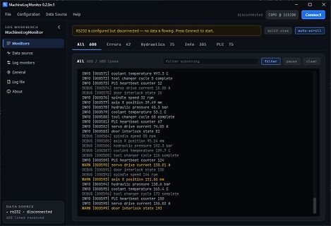
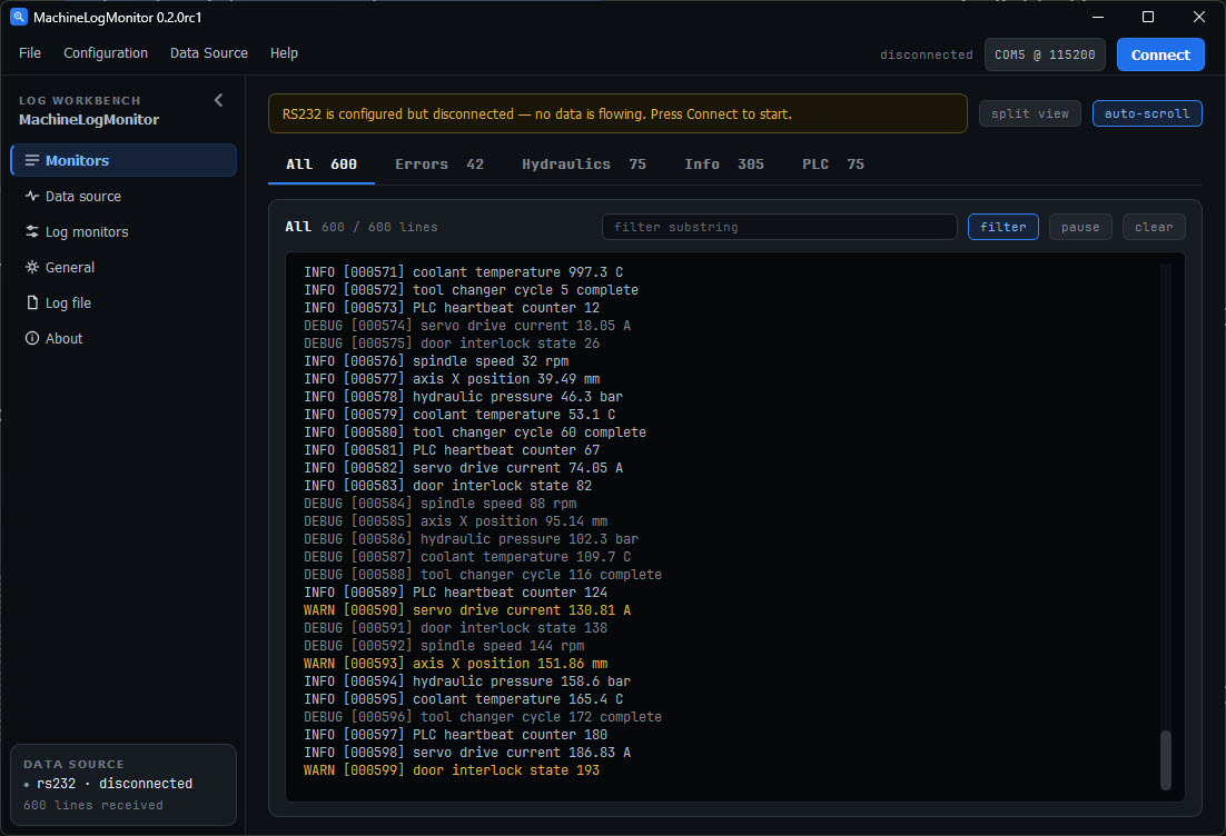
Screenshot einer Log-Monitor-Software mit Statusmeldungen
changer cycle 5 complete INFO [000573] PLC heartbeat counter 12 DEBUG [000574] servo drive current 18.05 A INFO [000576] spindle speed 37 rpm INFO [000577] axis X position 39.49 mm INFO [000578] hydraulic pressure 46.3 bar INFO [000579] coolant temperature 53.1 C INFO [000580] tool changer cycle 6 complete INFO [000581] PLC heartbeat counter 47 INFO [000582] servo drive current 74.05 A INFO [000583] door interlock state 12 DEBUG [000584] spindle speed 88 rpm DEBUG [000585] axis X position 95.14 mm DEBUG [000586] hydraulic pressure 102.3 bar DEBUG [000587] coolant temperature 109.7
in „MachineLogMonitor – Textlogs von RS232, CAN und CAN-Trace-Dateien mehrere gefilterte Ansichten“ · Projekte & Code · · Screenshots
-
PDF
hut1_12v2.pdf
ALPHANUMERIC DISPLAY PAGE (0X14)..............................................................................109 18.1 A LPHANUMERIC D ISPLAY..............................................................................................................111 18.1.1 Flags.............................................
in „USB HID Descriptor Spotify-Steuerung STM32“ · Mikrocontroller und Digitale Elektronik ·
-
PDF
Einheiten_deutsch.pdf
Basiseinheit Name Zeichen Länge Meter m Masse Kilogramm kg Zeit Sekunde s elektrische Stromstärke Ampere A Temperatur Kelvin K Stoffmenge Mol mol Lichtstärke Candela cd SI-Vorsätze Potenz Name Zeichen 24 1021 Yotta Y 10 Zetta Z 1018 Exa E 1015 Peta P 1012 Tera T 109 Giga G 6 103 Mega M 10 Kilo k 102 Hekto
in „Einheit gigasample??“ · Analoge Elektronik und Schaltungstechnik ·
-
PDF
schematic.PDF
C77 I44 1u C E PIN105 PID107 PID1013PIR1101 PIR11021 330R 100n 1u PIC501 PIC502 I1 CC8 V V BAL PID108A5 Y5 PID1012PIR1201 PIR12021 330R 1 CR133 R144 R151 CR166 R171 100n P18P14 9 A6 Y6 11 PODDUT1_N PIC602 PIC601 4IU101 0R 33R 33R 33R 1k PIC701 PIC702 8 4 PID109A7 Y7 PID1011 R1818 V1V CC9 5IU104 2 GND
-
Datei
convert_macro.asm
be adapted to match the actual circuitry ;splitted into sixten macros to speed up assembly .macro a1 .if @0==0 .set _x=112 .elif @0==1 .set _x=120 .elif @0==2 .set _x=121 .elif @0==3 .set _x=123 .elif @0==4 .set _x=126 .elif @0==5 .set _x=108 .elif @0==6 .set _x=109 .elif @0==7 .set _x=107 .elif @0
-
PDF
GYB-1C-24L-GOLDEN.pdf
andContacts 50Hz 500V Contact Material AgCdO;AgSnO 2,AgSnO 2InO 3 Between open contacts 50Hz 500V 4-1.4 NO:20A/14VDC 10A/120VAC Contact Rating(Res.Load) 5A/250VAC Operate time 10ms 15.7 12.3 NC:15A/14VDC,10A/120VAC 0 5A/250VAC Release time 5ms 1 1U:2 10A/14VDC 4 5 1 Max.Switching Power 280W 1250VA Shock Resistance
-
PDF
cr2032.pdf
higher.) removing batteries, battery compartments should be designed with one of the following methods: a) a tool such as screwdriver or coin is required to open battery compartment or b) the battery compartment door/cover requires the application of a minimum of two independent Simulated Application test
in „Smartphone Audiobuchse für Temperaturmessung“ · Mikrocontroller und Digitale Elektronik ·
-
PDF
CYWM6935pdf.PDF
marketed or in the product user’s guide. This should be in accompaniment with ■ Part 15 Section 15.109 Sub-paragraph A, Class B Radiated Emission Limits Document No. 38-16013 Rev. *C Page 3 of 9 CYWM6935 These emissions tests can be conducted by the manufacturer or These emissions tests can be conducted
-
Datei
NOKIA_TEST.asm
0x6A (106) = 'j' DT 0x00,0x7F,0x10,0x28,0x44 ; ASCII-Code 0x6B (107) = 'k' DT 0x00,0x41,0x7F,0x40,0x00 ; ASCII-Code 0x6C (108) = 'l' DT 0x7C,0x04,0x78,0x04,0x78 ; ASCII-Code 0x6D (109) = 'm' DT 0x7C,0x08,0x04,0x04,0x78
in „Ausgabe auf Nokia 3310 Display“ · Mikrocontroller und Digitale Elektronik ·
-
Datei
gcc-err-output.txt
’? 108 | __gthrw(pthread_equal) | ^~~~~~~ /usr/include/c++/9/x86_64-suse-linux/bits/gthr-default.h:109:1: error: ‘pthread_self’ was not declared in this scope; did you mean ‘pthread_key_t’? 109 | __gthrw(pthread_self) | ^~~~~~~ /usr/include/c++/9/x86_64-suse-linux/bits/gthr-default.h:109:1: error: ‘pthread_self
in „NanoVNA-QT Compilierung unter Suse Tumbleweed“ · Softwareentwicklung ·
-
Bild
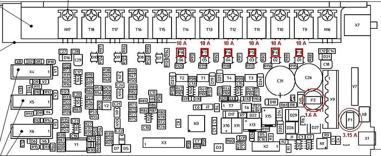
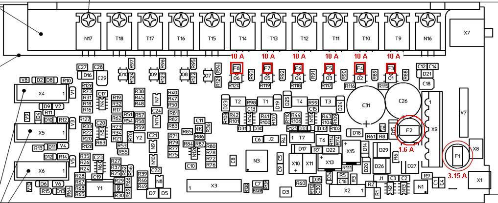
Leiterplatten-Layout eines Netzteils
N17 T18 T17 T16 T15 T14 T13 T12 T11 T10 T9 N16 X7 10 A F8 06 F7 05 F6 04 F5 03 F4 02 F3 01 1.6 A F2 X9 3.15 A F1 X8 X1 C26 C31 D24 D29 D18 D14 D26 D27 N1 3.15 A X1 X2 C16 C19 C21 C24 C26 C27 C28 C29 C31 C32 C35 C39 C46 C47 C48 C49 C50 C51 C52 C53 C54 C55
in „Weller WR3M /WD3M Triacs sterben“ · Analoge Elektronik und Schaltungstechnik · · Layouts
-
Thread
5x7 LED Matrix Laufschrift - Abstand zwischen Zeichen
69 {0x7f,0x09,0x09,0x09,0x01}, // F 0x46 70 {0x3e,0x41,0x49,0x49,0x7a}, // G 0x47 71 {0x7f,0x08,0x08,0x08,0x7f}, // H 0x48 72 {0x00,0x41,0x7f,0x41,0x00}, // I 0x49 73 {0x20,0x40,0x41,0x3f,0x01}, // J 0x4a 74
{0x00,0x44,0x7d,0x40,0x00}, // i 0x69 105 {0x20,0x40,0x44,0x3d,0x00}, // j 0x6a 106 {0x00,0x7f,0x10,0x28,0x44}, // k 0x6b 107 {0x00,0x41,0x7f,0x40,0x00}, // l 0x6c 108 {0x7c,0x04,0x18,0x04,0x78}, // m 0x6d 109 {0x7c
Mikrocontroller und Digitale Elektronik ·Yves K. · ·2 Antworten
-
PDF
MC57T01G.pdf
www.SpecLcd.com 3.2 Outline Dimension 2.15 0.3 104.7 0.5(T/P Screen Outline) 7.575 0.3 93.85 0.3(T/P V.A) ± 0.3 0.05 (50.5) R ± T 5.0 0.3 C P1.0x3=3.0 U (41.75) N 1 4 O 1 4 C 2 C S 0 4-3.3 0.3 S A 0 2 2 E . - J 0 N . A ± - 2 C 0 T 4 I ( 5 . 4 ± 0 4 ? 1 -3 5 T S H T I O R D 0 4 2 ) ) B A G A R D 3 L X N
in „Grasshopper und TFT Display“ · Mikrocontroller und Digitale Elektronik ·
-
PDF
LCD_MC57T01G.pdf
www.SpecLcd.com 3.2 Outline Dimension 2.15 0.3 104.7 0.5(T/P Screen Outline) 7.575 0.3 93.85 0.3(T/P V.A) ± 0.3 0.05 (50.5) R ± T 5.0 0.3 C P1.0x3=3.0 U (41.75) N 1 4 O 1 4 C 2 C S 0 4-3.3 0.3 S A 0 2 2 E . - J 0 N . A ± - 2 C 0 T 4 I ( 5 . 4 ± 0 4 ? 1 -3 5 T S H T I O R D 0 4 2 ) ) B A G A R D 3 L X N
in „Farb LCD 320x240“ · Markt ·
-
Bild
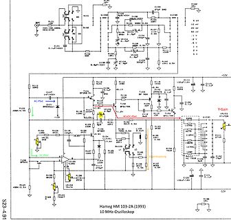
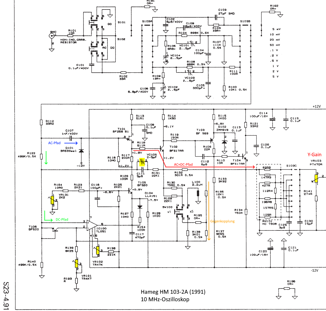
Schaltplan eines 10 MHz Oszilloskops
S101, S102, S103A, S103B, R101, R102, R103, R104, R105, R106, R107, R108, R109, R110, R111, R112, R113, R114, R115, R116, R117, R118, R119, R120, R121, R122, R123, R124, R125, R126, R127, R128, R129, R130, R131, R132,
in „Schaltungstechnik Oszilloskop-Y-Eingangsverstärker (Hameg)“ · Analoge Elektronik und Schaltungstechnik · · Schaltpläne
-
PDF
320240A.pdf
BN320240A 160.0±0.2 11.0 152.0±0.2 4.0 7.0 11.0±0.5 141.0 14.7 121.0(V.A) 1.0 115.17(A.A) 20 16 2 X 5 1 1 8 9 X 9 1 1 3 3 8 J1 J2 = 0 5 0 V A 6 3 2 2 A ) DOTS:320X240 2 ) 1 1 3 . 0 5 0 4-Ø3.53 6 0.36 0.33 MECHANICAL
-
Datei
webserver-atmega644.txt
the source for copying conditions. There is NO warranty; not even for MERCHANTABILITY or FITNESS FOR A PARTICULAR PURPOSE. Compiling: main.c avr-gcc -c -mmcu=atmega644 -I. -g -Os -funsigned-char -funsigned-bitfields -fpack-struct -fshort-enums -Wall -Wstrict-prototypes -Wa,-adhlns=main.lst -std=gnu99
in „too many arguments to function `fdevopen'“ · Mikrocontroller und Digitale Elektronik ·
-
Datei
main.c
,0x1c,0x1e, 0x20,0x22,0x24,0x26,0x28,0x2a,0x2c,0x2e,0x30,0x32,0x34,0x36,0x38,0x3a,0x3c,0x3e, 0x40,0x42,0x44,0x46,0x48,0x4a,0x4c,0x4e,0x50,0x52,0x54,0x56,0x58,0x5a,0x5c,0x5e, 0x60,0x62,0x64,0x66,0x68,0x6a,0x6c,0x6e,0x70,0x72,0x74,0x76,0x78,0x7a
in „Falsche Ausgangsfrequenz“ · Mikrocontroller und Digitale Elektronik ·
-
Bild
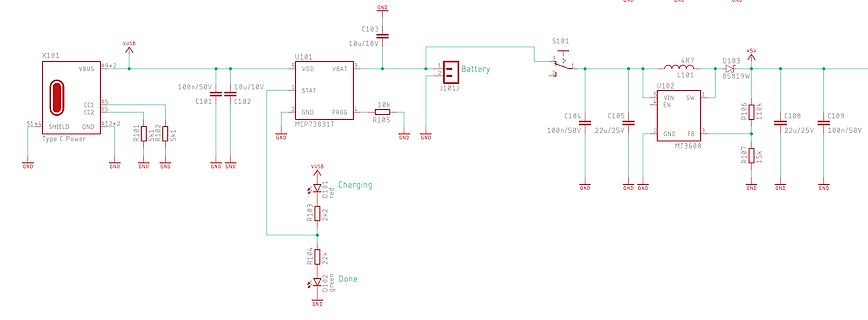
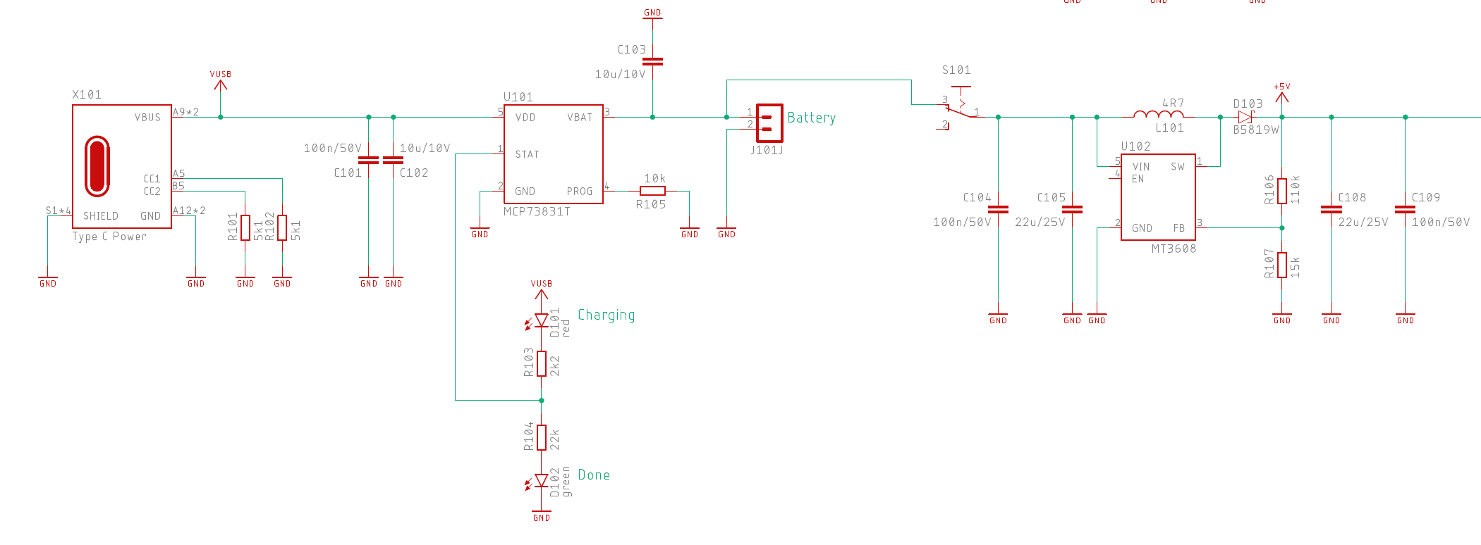
Schaltplan einer Akku-Ladeschaltung mit USB-C
X101 VBUS A9*2 CC1 CC2 GND A12*2 SHIELD Type C Power R101 10R GND R102 5k1 GND C101 100n/50V GND C102 10u/10V GND U101 VDD VBAT STAT PROG GND MCP73831T R105 10k GND GND C103 10u/10V S101 GND L101 4R7 D103 B5819W +5V U102 VIN SW EN FB GND MT3608 R106 110k C104 100n/50V C105 22u/25V GND C108 22u/25V C109 100n/50V R107 15k GND VUSB D101 red Charging R103 2k2 D102 green Done R104 22k GND
in „Prüfung Schaltplan Flight Controller“ · Mikrocontroller und Digitale Elektronik · · Schaltpläne
-
PDF
Amilo_Spannungen.pdf
5 4 3 2 1 Q10 Q6 Q14 RSS090N03 >4A RSS090N03 >4A RSS090N03 >1A 8 1 8 1 8 1 +3V_AUX 7 2 +3V +5V_AUX 7 2 +5V +1.8V_AUX 7 2 +1.8V 01 6 3 VIN 6 3 VIN 6 3 VIN 5 S 5 S 5 S D C104 D C58 D C255 R57 G 100n/50V_0603 R55 R22 G 1n/50V_0603 R28 R100
in „Laptop geht nicht an: MOSFET 4C06N?“ · Analoge Elektronik und Schaltungstechnik ·
-
Datei
main.c
2,3,10,11,12,13,0,1}, {6,7,14,15,17,16,4,5}, {102,103,8,9,18,19,100,101}, {110,111,104,105,106,107,108,109}}; uint8_t last_val = 0; uint8_t buffer[128]; void update_changes(uint8_t cc, uint8_t val) { //if(val != buffer[cc]) { midi_send_cc(cc, val); midi_send_cc(cc, buffer[cc]); midi_send_cc(cc, val != buffer
in „ATmega8 Probleme mit Vergleichen“ · Mikrocontroller und Digitale Elektronik ·
-
PDF
SED1565.pdf
continuously. See the function explanation in “The Column Address Circuit,” for details. E R/W Column A0 RD WR D7 D6 D5 D4 D3 D2 D1 D0 A7 A6 A5 A4 A3 A2 A1 A0 address High bits → 0 1 0 0 0 0 1 A7 A6 A5 A4 0 0 0 0 0 0 0 0 0 Low bits → 0 A3 A2 A1 A0 0 0 0 0 0 0 0 1 1 0 0 0 0 0 0 1 0 2 ↓ ↓ 1 0 0 0 0 0 1 0
in „Pollin 128x64 GLCD : Bild verzerrt“ · Mikrocontroller und Digitale Elektronik ·
-
PDF
Betriebsanleitung_optoNCDT_1420pdf__1_.pdf
....................................................109 A 3.5.4 OUTHOLD, Fehlerbehandlung....................................................................................................109 A 3.5.5 Auswahl der auszugebenden Messwerte...................................................................................109 A 3.5.5.1 GETOUTINFO_RS422, Abfrage Datenauswahl.........................................................109 A 3.5.5.2 OUTADD_RS422, Datenauswahl zusätzliche Werte ..................................
in „Sensor mit RS422 interface und Konverter verbunden an Esp32 via TTL“ · Mikrocontroller und Digitale Elektronik ·
-
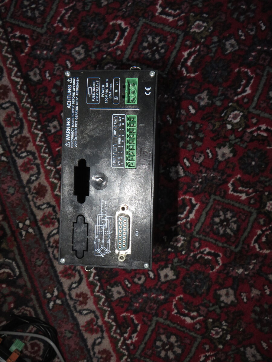
Bild
Rückseite eines Netzteils mit Anschlussklemmen
ACHTUNG DISCONNECT MAINS SUPPLY BEFORE OPENING VOR OFFENEN DES NETZ ABTRENNEN FUSE / INPUT 315A / 1A POWER 230V / 50, 60 Hz VA N L1 CE L N 1 2 3 4 5 6 7 8 9 10 11 12 13 14 15 16 17 18 19 20 21 22 23 24 25 26 27 28 29 30 31 32 33 34 35 36 37 38 39 40 41 42 43 44 45 46 47 48 49 50 51 52 53 54 55
in „[V] 2 Stück Anzeiger MVD 2510“ · Markt · · Fotos
-
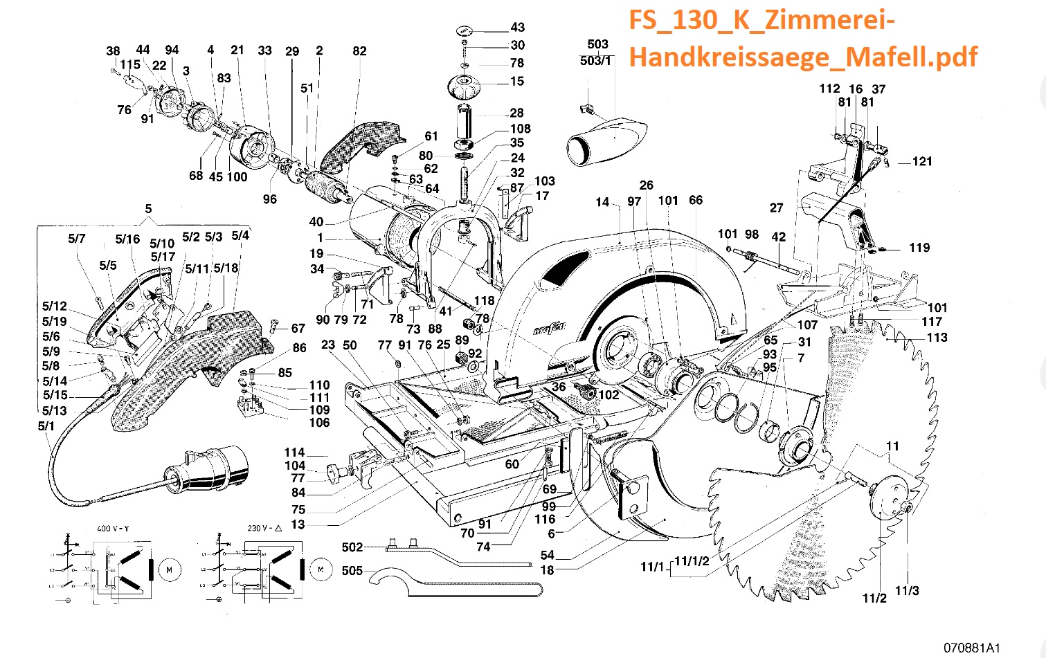
Bild
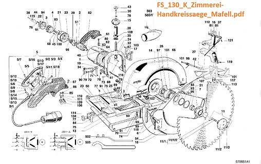
Explosionszeichnung einer Handkreissäge
11/1 11/2 11/3 11/2 102 36 88 89 92 78 73 41 118 19 34 40 1 90 79 72 23 50 77 76 25 86 85 110 111 109 106 5/12 5/19 5/6 5/9 5/14 5/15 5/13 5/1 5/10 5/17 5/2 5/3 5/5 67 114 104 77 84 75 13 60 69 99 116 70 91 74 54 18 502 505 400 V-Y 230 V-A 070881A1
in „blauer Bosch Winkelschleifer geht plötzlich aus - tot ?“ · Analoge Elektronik und Schaltungstechnik · · Diagramme
-
Bild
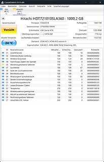
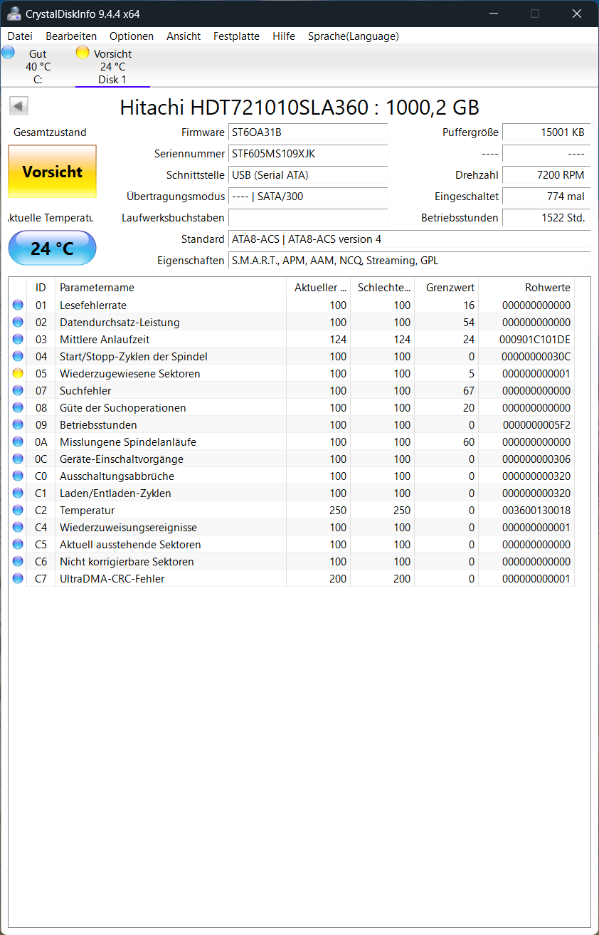
CrystalDiskInfo S.M.A.R.T. Werte einer Hitachi Festplatte
9.4.4 x64 Hitachi HDT721010SLA360 : 1000,2 GB Gesamtzustand Vorsicht 40 °C 24 °C Disk 1 Firmware ST60A31B Seriennummer ST60FS109XJK Schnittstelle USB (Serial ATA) Drehzahl 7200 RPM Übertragungsmodus ---- | SATA/300 Eingeschaltet 774 mal Betriebsstunden 1522 Std. Laufwerksbuchstaben Standard ATA8-ACS | ATA8-ACS version 4 Eigenschaften S.M.A.R.T., APM, NCQ, Streaming, GPL ID Parameter aktuelle schlechte grenzwert 01 Lesefehler 100 100 16 000000000000 04 Start/Stop-Zyklen 100 100 54 000000000000 05 Wiederzugewiesene Sektoren 100 100 5 000000000001
in „[V] 3,5" SATA HDD's - 4x 1TB, 3TB, 80GB, 160GB und USB3.0-Adapter“ · Markt · · Screenshots
-
PDF
SARA-G3_DataSheet__UBX-13000993_.pdf
electrical specs. 7 All RI GDI O UART ring indicator Circuit 125 (RI) in ITU-T V.24. Output driver class A. PU/PD class b. Value at reset: T/PU. See section 4.2.11 for detailed electrical specs. 8 All DCD GDI O UART data carrier Circuit 109 (DCD) in ITU-T V.24. detect Output driver class A. PU/PD class a.
in „GSM-Modul (SIM908) nur analoge Ausgänge für Anruf?“ · HF, Funk und Felder ·
-
PDF
FE560IA.pdf
M O D U L A R I N S T R U M E N T A T I O N FE-560-IA Isolation Amplifier The FE-560-IA is an Isolation Amplifier in the FYLDE "blue panel" modular range of signal conditioning, and is a general purpose isolation
-
Bild
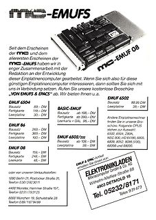
Werbeanzeige für MC-EMUFS Einplatinencomputer
Einplatinencomputer interessieren, dann sollten Sie sich mit uns in Verbindung setzen, ab. Wir bieten Ihnen u.a. EMUF 6504 Bausatz 89,- DM Fertigkarte 119,- DM Leerplatine 30,- DM EMUF 6502 Bausatz 99,55 DM Leerplatine 39,- DM BASIC-EMUF Bausatz ab 198,- DM Fertigkarte + GAL 390,- DM Leerkarte 98,- DM EMUF 86 Bausatz 269,- DM Fertigkarte 369,- DM Leerplatine 100,- DM EMUF 6502/232 Bausatz ab 109,- DM Leerplatine 39,- DM EMUF 08 Bausatz 159,- DM Fertigkarte 248,- DM Leerkarte 48,- DM Andere Einplatinenrechner finden Sie in unserer Broschüre. Folgende CPUS stehen zur Auswahl: 6502, 6504, Z80A
in „MC EMUF08 Monitorprogramm“ · Mikrocontroller und Digitale Elektronik · · Sonstiges
-
PDF
Netztransformator__prim__230_V___sek.__28_V_3_3_A_sowie_2_x_8_V_500_mA___ELV-Elektronik.pdf
Heizungsregler Beleuchtung - LED / Halogen Netztransformator, prim: 230 V˜, Sicherheitstechnik sek.: 28 V/3,3 A sowie 2 x 8 V/500 Klima - Wetter - Umwelt mA Multimedia - Sat - TV - Audio Artikel-Nr.: 68-02 23 85 Computer- / Netzwerktechnik Kommunikation - Telefon/Handy Artikel vergleichen Artikel vergleichen Kfz-Technik
in „Trafo 230/28 & 8V gesucht“ · Analoge Elektronik und Schaltungstechnik ·
-
PDF
nkat20-21.pdf
. Best.Nr. St. ab 10 ab 100 ab 500 ab 2000 10 µF 6.3 V R 7236/12 -.89 -.315 -.175 -.135 10 µF 10 V A 7236/111 -.59 -.176 -.098 -.075 -.062 10 µF 16 V A 7236/111C -.65 -.203 -.113 -.087 -.072 10 µF 16 V B 7236/106 -.63 -.197 -.109 -.084 -.070 10 µF 20 V B 7236/106F -.78 -.264 -.146 -.113 -.093 10 µF
-
PDF
Kempster_et_al._2013.pdf
were applied at three major intensities (0.4– current to be varied and the function generator enabled a specific 0.6 mV/cm, 0.9–1.1 m V/cm and 1.9–2.1 mV/cm) via a function wave form to be selected and the output frequency controlled. An generator and a custom built stimulus generator [25] with an ammeter
in „Versuchsaufbau mit Oszilloskop und Funktionsgenerator“ · Analoge Elektronik und Schaltungstechnik ·
-
PDF
quellenwahl.pdf
CEX3 P0U108 8 P P3.2/INT0 P1.7/CEX4 K2 13 P0U1013 D3 P3.3/INT1 0 Relay-DPST GND 14 P0UP3.4/T0 P2.0/A8 P0U1021 21 Diode 1N4007 D 0 0 0 15 P0U1015 P0U1022 22 P 0 0 0 P3.5/T1 P2.1/A9 P P P 16 P0U1016 P0U1023 23 0 17 P3.6/WR P2.2/A10 P0U1024 24 Q PP3.7/RD P2.3/A11 D4 P P0U1025 25 Tuner Eingang P2.4/A12 P0U1026 P0D402 P0D401P0R401 P0R402P0Q302 Q3 P2.5/A13 26 BC337 P0U1027 27 R4 1 P2.6/A14 Q 20 P0U102VSS P2.7/A15 P0U1028 28 470 P LED1 P80C54SFPN GND GND D Title D Size Number Revision A4 Date: 01.01.2008 Sheet of File: C:\Verstärker\quellenwahl.SchDoc
in „Mikrocontroller für Verstärker(Quellenwahl)“ · Analoge Elektronik und Schaltungstechnik ·
-
PDF
quellenwahl.pdf
INT0 P1.7/CEX4 K2 13 P0U1013 0470 Relay-DPST GND 14 P3.3/INT1 P0U1021 21 0 3 6 4 2 P0UP3.4/T0 P2.0/A8 1 0 2 2 2 15 P0U1015 P0U1022 22 D P 0 0 0 P3.5/T1 P2.1/A9 P0U1023 P P P P 16 PP3.6/WR P2.2/A10 23 17 P0U1017 P0U1024 24 D4 P3.7/RD P2.3/A11 2 P0U1025 25 LED1 D Tuner Eingang P2.4/A12 P0U1026 26 P P2.5/A13 3 P0U1027 27 3 P2.6/A14 0 20 P0U1020 P0U1028 28 P VSS P2.7/A15 R5 Q3 P0R501 P0R502 P0Q302 P80C54SFPN BC337 Res2 0 10K Q P GND Title D D GND Size Number Revision A4 Date: 02.01.2008 Sheet of File: C
in „Mikrocontroller für Verstärker(Quellenwahl)“ · Analoge Elektronik und Schaltungstechnik ·
-
PDF
vigortronix_VTX-214-001-xxx.pdf
EN61558, EN60950, CE Power Rating Output Output Current Ambient Efficiency Part Number Watts Voltage (mA) Temp. ( C) Typical Input Range (VDC) 300 VTX-214-001-103 1 3.3 200 VTX-214-001-105 1 5 167 VTX-214-001-106 1 6 133 VTX-214-001-107 1 7.5 VTX-214-001-108 1 8 125 VTX-214-001-109 1 9 111 70 >60% 90 -
in „AC/DC-Wandler 3.3V/1W vigortronix Ripple“ · Analoge Elektronik und Schaltungstechnik ·
-
PDF
33963.pdf
2.010E+03 1.90 0.666 38 56 2.862E+02 2.15 2.072 13 19 1.909E+03 1.93 0.703 39 57 2.719E+02 3.19 2.109 14 20 1.814E+03 1.96 0.740 3A 58 2.583E+02 3.22 2.146 15 21 1.723E+03 1.99 0.777 3B 59 2.454E+02 3.25 2.183 16 22 1.637E+03 2.03 0.814 3C 60 2.331E+02 3.28 2.220 17 23 1.555E+03 2.06 0.851 3D 61 2.215E
in „[V] 2St Dallas DS1633 Ladechip TO220 3 Pin für“ · Markt ·
-
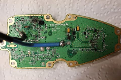
Bild
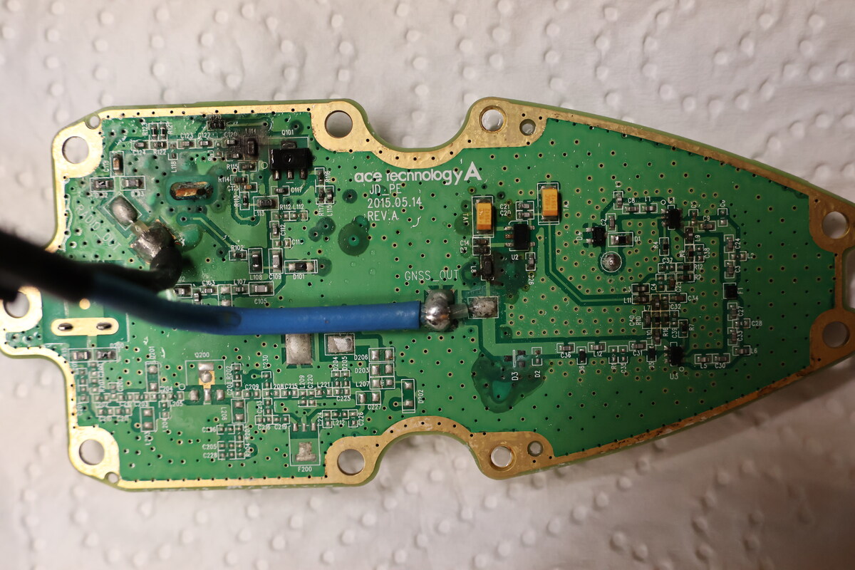
Foto einer Leiterplatte mit Kabelanschluss
ace technology A JD_PF 2015.05.14 REV.A GNSS_OUT C101 C102 C103 C104 C105 C106 C107 C108 C109 C110 C111 C112 C113 C114 C115 C116 C117 C118 C119 C120 C121 C122 C123 C124 C125 C126 C127 C128 C129 C130 C131 C132 C133 C134
in „Kia Ceed FM/GPS Antenne defekt“ · Platinen · · Platinenfotos
-
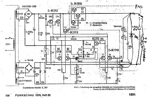
Bild
Schaltplan eines geregelten Netzteils
220V~ 30V/3A 0,33 2 1N4148 3Atr 2x BC252 390 7,5k T1 T2 T3 3x 2N3055 0,2 0,2 68 1k S2 1:1 Strombegrenzung 2=Abschalten Spannung P1 10k P2 1k 100u 35V 2x BC171B T6 1N4148 2x 1N4148 9 Grün S2 11 12 T7 1k 13 2x BC171B
in „Unbekanntes Labornetzteil“ · Analoge Elektronik und Schaltungstechnik · · Schaltpläne
-
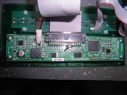
Bild
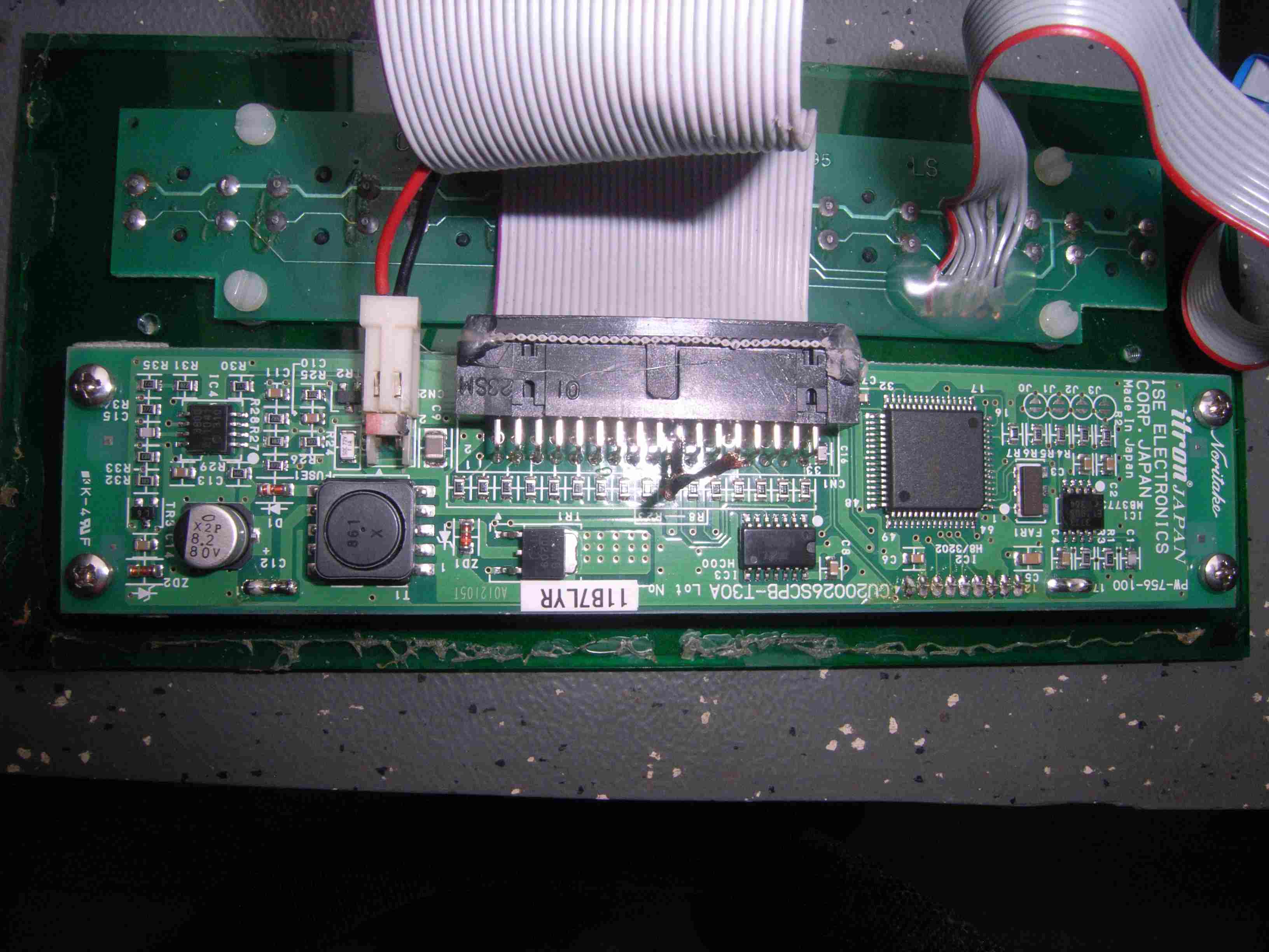
Elektronische Leiterplatte mit Flachbandkabel
R37 R35 R31 R30 C11 R2 R25 C10 CN2 U23SH 32 CY 31 30 29 28 27 17 C15 R33 R32 C19 R34 C12 A08 ZD2 T1 A0121051 11B7LYR Lot No. CU20026SCPB-T30A CN1 R11 R12 R13 R14 R15 R16 R17 R18 R19 R20 R21 R22 R23 R24 R25 R26 R27 R28 R29 R30 R31 R32 R33 R34 R35 R36 R37 R38 R39 R40 R41 R42 R43 R44 R45 R46
in „VFD Display Ersatz“ · Mikrocontroller und Digitale Elektronik · · Platinenfotos
-
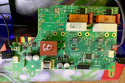
Bild
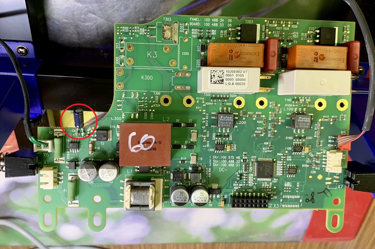
Leiterplatte eines Netzteils mit Kondensatoren und Transformatoren
T303 PANEL: 100 488 34 06 T203 R222 R23 R25 R227 R29 R201-1A4-D006 SCHRACK D302 D17 R201-1A4-D006 SCHRACK 1020882.01 0001 0105 0000 0000 LG A 00020 K3 C355 D205 L300 L2 06 D7 R310 R248 R31 R32 R31 R33 R34 R35 R104 R105 L100 R12 R11 R13 R14 R15 R16 R17 R18 R19
in „Kostal PV-Wechselrichter wacht nicht von selbst auf“ · Haus & Smart Home · · Platinenfotos
-
Bild
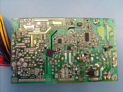
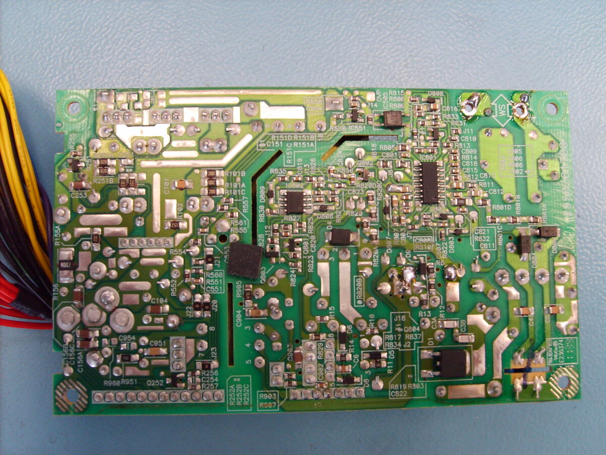
Bestückte grüne Leiterplatte mit elektronischen Bauteilen
R255 R251B C253 R155A R156 C156A R960 R951 Q252 R257 R256 R253B R252C R903 R907 C522 R819 R803 R837 R817 R13 J18 R10 R829 R828 R824 R823 R822 R821 R820 R818 R811 C812 R813 C811 R814 R815 R816 R833 R831 R830 R805 R806 R808 R810 R151D R151B C151 R151A R15 R835 R191B R191C R157 R156 R155 R151 R150 R149 R148 R147 R146 R145 R144 R143 R142 R141 R140 R139 R138 R137 R136 R135 R134 R133 R132 R131 R130 R129 R128 R127 R126 R125 R124 R123 R122 R121 R120 R119
in „ungeglättetes Schaltnetzteil“ · Analoge Elektronik und Schaltungstechnik · · Platinenfotos
-
PDF
vhfcindex.pdf
, Block Diagrams, 70 cm Band Variations I Sangmeister, DJ7OH 1977/2 104 - 108 Measuring Technology A Spectrum Analyser for Amateur Applications E Berberich, DL8ZX 1977/2 109 - 120 Audio Frequency A Triangular Wave Generator H J Ehrke, DC7LE 1977/2 121 - 123 Technology Measuring A Triangular Wave Generator
-
PDF
XC95288_Auszug.pdf
K6, L7, F8, L8, F9,9, U12, V16, R17, T20,M19,F20,E17, L9, F10, L10, G11, M18, G18, D19, B17, B14, A10, C7, H11, J11, K11 C18, A15, A11, D8, B3, G4 A4 VCCIO2.5V/3.3 V 1,37,55,73,109,1, 26, 53, 65, 79D4, D6, D11, D15,F3, K4, D5, F6, L6,C3, F1, K1, N4, V2 127 92,105,132,157, D17, F4, F17, K4, P6, C7,
in „miniLa Software“ · Projekte & Code ·
-
PDF
UP-RW1245P1.pdf
PleasecontactPanasonicforavailabilityonoptionalitems. Optionalitemsmaybesubjectto o 11.4 minimumorderquantities. v 10.8 a 10.2 2.25A i 9.6 9A Characteristics m 9.0 e 8.4 Capacity (note) 30 minute rate 112W T 7.8 27A 15 minute rate 195W 77˚F (25˚C) 10 minute rate 268W 0 1 2 4 6 8 10 20 40 6080 100 200 (9.6V Cutoff) 5 minute
in „Messung Leistungsaufnahme mit USV“ · PC Hard- und Software ·
-
PDF
UP-RW1245P1.pdf
PleasecontactPanasonicforavailabilityonoptionalitems. Optionalitemsmaybesubjectto o 11.4 minimumorderquantities. v 10.8 a 10.2 2.25A i 9.6 9A Characteristics m 9.0 e 8.4 Capacity (note) 30 minute rate 112W T 7.8 27A 15 minute rate 195W 77˚F (25˚C) 10 minute rate 268W 0 1 2 4 6 8 10 20 40 6080 100 200 (9.6V Cutoff) 5 minute
in „BleiAkku - Kapazität messen“ · Mikrocontroller und Digitale Elektronik ·
-
PDF
UP-RW1245P1.pdf
PleasecontactPanasonicforavailabilityonoptionalitems. Optionalitemsmaybesubjectto o 11.4 minimumorderquantities. v 10.8 a 10.2 2.25A i 9.6 9A Characteristics m 9.0 e 8.4 Capacity (note) 30 minute rate 112W T 7.8 27A 15 minute rate 195W 77˚F (25˚C) 10 minute rate 268W 0 1 2 4 6 8 10 20 40 6080 100 200 (9.6V Cutoff) 5 minute
in „AGM-Bleiakkus: Höhere Kapazität bei gleicher Größe Unsinn?“ · Analoge Elektronik und Schaltungstechnik ·
-
PDF
1120error.pdf
Off Off Off 2-13 HP Designjet T Series — Service Manual System Error Codes - Full Descriptions 3 n/a Formatter. Page 6-204 On On Off Off Hard Disk Drive. 4 On * Flashin* Off Off n/a Page 6-204 Hard Disk Drive. 5 On On * Flashin* Off n/a Page 6-204 6 n/a 1. Formatter. Page 6-204 On On On Off 2. Main PCA. Page 6-209 7 On On On *Flashing* n/a Main PCA. Page 6-209 First check the front panel. Page 6-47 Front-panel If necessary, check the 8 On On On On light on Main PCA. Page 6-209 Then check the front-panel cable. Page 6-47 Check the front-panel
in „HP Plotter T1120 weißer Bildschirm nach Transport“ · PC Hard- und Software ·
-
PDF
drehgeber_Eig.pdf
1000 Versorgungsspannung 10 bis 30V DC Gehäuse Ø 39mm Leerlaufstrom 30mA Maximale Anzahl von Umdrehungen 10000U/min IP Nennwert Gehäuse IP50 Beschreibung Drehgeber RI38-Inkremental, Welle, 38mm Mechanische Daten Wellen Ø: 6mm Wellenbelastung: radial 10N, axial 5N 1 von 3
in „rechteck signal aus sinus“ · Mikrocontroller und Digitale Elektronik ·
-
Bild
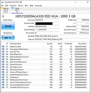
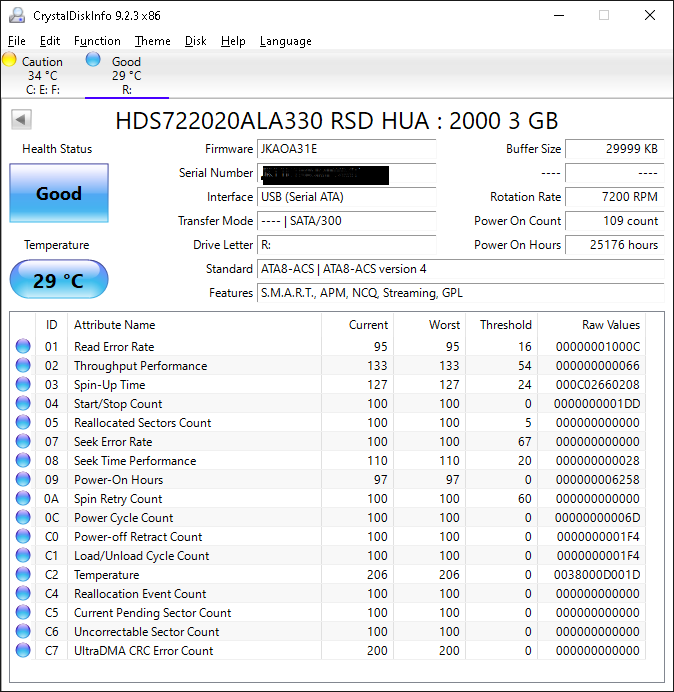
S.M.A.R.T.-Werte einer Festplatte
Number Interface USB (Serial ATA) Rotation Rate 7200 RPM Transfer Mode ----| SATA/300 Power On Count 109 count Temperature 29 °C Power On Hours 25176 hours Drive Letter R: Standard ATA8-ACS Features S.M.A.R.T., APM, NCQ, Streaming, GPL ID Attribute Name Current Worst Threshold Raw Values 01 Read Error
in „Linux: Low Level Tools für USB Stick gesucht“ · PC Hard- und Software · · Screenshots